2007 ISUZU KB P190 light
[x] Cancel search: lightPage 5789 of 6020
CAB 10-31
RTW 7A0SH000301
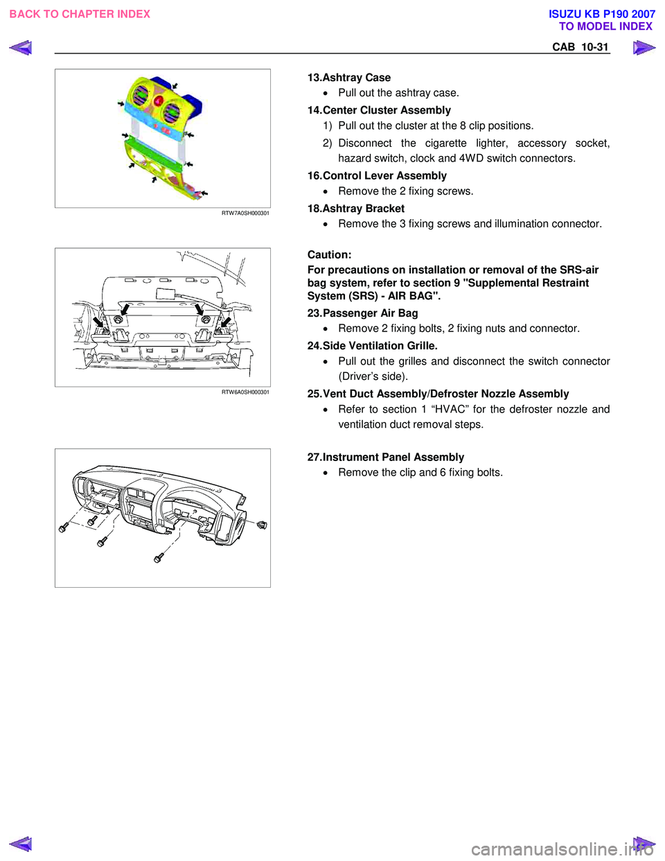
13.Ashtray Case
• Pull out the ashtray case.
14. Center Cluster Assembly 1) Pull out the cluster at the 8 clip positions.
2) Disconnect the cigarette lighter, accessory socket, hazard switch, clock and 4W D switch connectors.
16. Control Lever Assembly • Remove the 2 fixing screws.
18.Ashtray Bracket • Remove the 3 fixing screws and illumination connector.
RTW 6A0SH000301
Caution:
For precautions on installation or removal of the SRS-air
bag system, refer to section 9 "Supplemental Restraint
System (SRS) - AIR BAG".
23. Passenger Air Bag
• Remove 2 fixing bolts, 2 fixing nuts and connector.
24. Side Ventilation Grille. • Pull out the grilles and disconnect the switch connecto
r
(Driver’s side).
25. Vent Duct Assembly/Defroster Nozzle Assembly • Refer to section 1 “HVAC” for the defroster nozzle and
ventilation duct removal steps.
27. Instrument Panel Assembly
• Remove the clip and 6 fixing bolts.
BACK TO CHAPTER INDEX TO MODEL INDEX
ISUZU KB P190 2007
Page 5798 of 6020
10-40 CAB
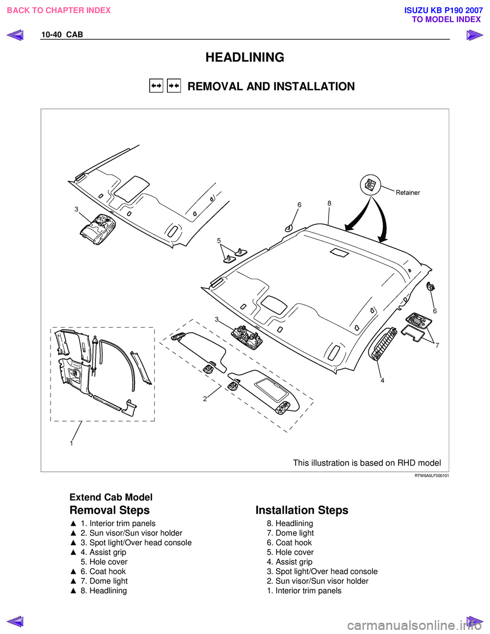
HEADLINING
REMOVAL AND INSTALLATION
This illustration is based on RHD model
RTW 6A0LF000101
Extend Cab Model
Removal Steps
▲ 1. Interior trim panels
▲ 2. Sun visor/Sun visor holder
▲ 3. Spot light/Over head console
▲ 4. Assist grip
5. Hole cover
▲ 6. Coat hook
▲ 7. Dome light
▲ 8. Headlining
Installation Steps
8. Headlining
7. Dome light
6. Coat hook
5. Hole cover
4. Assist grip
3. Spot light/Over head console
2. Sun visor/Sun visor holder
1. Interior trim panels
BACK TO CHAPTER INDEX TO MODEL INDEX
ISUZU KB P190 2007
Page 5799 of 6020
CAB 10-41
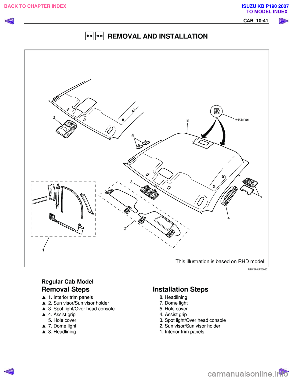
REMOVAL AND INSTALLATION
This illustration is based on RHD model
RTW 6A0LF000201
Regular Cab Model
Removal Steps
▲ 1. Interior trim panels
▲ 2. Sun visor/Sun visor holder
▲ 3. Spot light/Over head console
▲ 4. Assist grip
5. Hole cover
▲ 7. Dome light
▲ 8. Headlining
Installation Steps
8. Headlining
7. Dome light
5. Hole cover
4. Assist grip
3. Spot light/Over head console
2. Sun visor/Sun visor holder
1. Interior trim panels
BACK TO CHAPTER INDEX TO MODEL INDEX
ISUZU KB P190 2007
Page 5800 of 6020
10-42 CAB
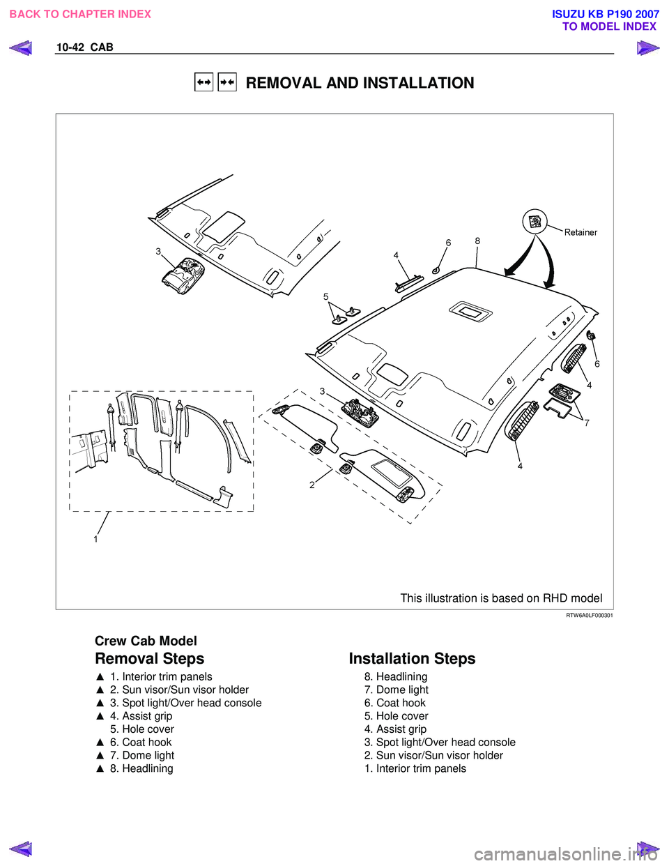
REMOVAL AND INSTALLATION
This illustration is based on RHD model
RTW 6A0LF000301
Crew Cab Model
Removal Steps
▲ 1. Interior trim panels
▲ 2. Sun visor/Sun visor holder
▲ 3. Spot light/Over head console
▲ 4. Assist grip
5. Hole cover
▲ 6. Coat hook
▲ 7. Dome light
▲ 8. Headlining
Installation Steps
8. Headlining
7. Dome light
6. Coat hook
5. Hole cover
4. Assist grip
3. Spot light/Over head console
2. Sun visor/Sun visor holder
1. Interior trim panels
BACK TO CHAPTER INDEX TO MODEL INDEX
ISUZU KB P190 2007
Page 5801 of 6020
CAB 10-43
Important Operations - Removal
1. Interior Trim Panels • Refer to Interior Trim Panels in this section.
2. Sun visor/Sun visor Holder
1) Remove the 2 screws fixing the sun visor.
2) Remove the screw fixing the sun visor holder.
3. Spot Light/Over Head Console
• Refer to section 8 Spot Light.
• Refer to section 8 Over Head Console.
RUW 5A0SH003401
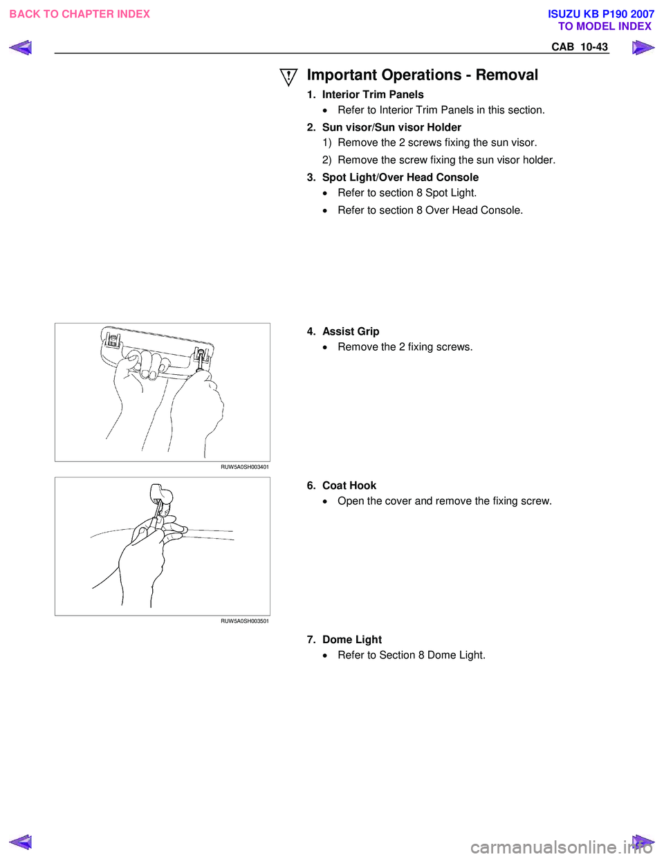
4. Assist Grip
• Remove the 2 fixing screws.
RUW 5A0SH003501
6. Coat Hook
• Open the cover and remove the fixing screw.
7. Dome Light
• Refer to Section 8 Dome Light.
BACK TO CHAPTER INDEX TO MODEL INDEX
ISUZU KB P190 2007
Page 5889 of 6020
11A-38 IMMOBILIZER CONTROL SYSTEM (4JK1/4JJ1/HFV6)
PIM Programming Procedure must be done
whenever any of the following condtions are met:
• Diagnostic chart instructs you to program PIM
• New PIM is installed
• PIM is reused that was rest in an original vehicle
ICU & PIM Programming Procedure must be done
whenever any of the following condition is met:
• New or resued ICU and PIM are installed at the same time
ECM & PIM Programming Procedure must be done
whenever any of the following condition is met:
• New or reused ECM and PIM are installed at the same time
ICU & ECM Programming Procedure must be done
whenever any of the following condition is met:
• New or reused ICU and ECM are installed at the same time (transponder key(s) also replaced)
ICU, ECM & PIM Programming Procdure must be
done whenever any of the following condition is met:
• New or reused ICU, ECM and PIM are installed at the same time (transponder key(s) also replaced)
Notice: During programming of the new transponder
key(s), an authentication code is programmed into the
transponder chip and it cannot be reprogrammed
again. When replacing both ICU and ECM at the same
time, a new authentication code to be programmed into
the newly installed ECM is based on information of
newly installed ICU. However, the transponder keys
cannot be reprogrammed therefore it must be replaced.
Do not replace the ICU and the ECM at the same time
to avoid needless transponder key(s) replacement
simultaneously unless complete damaging was
encountered (e.g. both modules cannot be
communicated with a scan tool).
Transponder Key Erasing Procedure
1. Install a scan tool.
2. Turn ON the ignition, with the engine OFF.
3. Select Diagnostics > Appropriate vehicle identification > Body > Immobilizer > Additional
Functions > Erase Transponder Keys.
4. The on-screen displays a message "See Checking Procedure Before Programming!", then press
Confirm.
5. Input four digits of correct security code that belongs to this vehicle and follow the on-screen
instructions. Notice:
An incorrect security code input causes a
security wait time.
6. The on-screen displays a message "Caution All Transponder Keys Will Be Erased!", then press
Confirm.
7. Operate the ignition switch by following the on- screen instructions.
8. The on-screen displays a message "Erase Transponder Keys Erasing Completed
Successfully!" if transponder erasing has been
completed, then press Confirm.
9. Turn OFF the ignition for 30 seconds.
10. Verify the engine fails to run using all transponder key(s).
Transponder Key Programming Procedure
1. Install a scan tool.
2. Turn ON the ignition, with the engine OFF.
3. Select Diagnostics > Appropriate vehicle identification > Body > Immobilizer > Programming
> Program Transponder Keys.
4. In order to get a programming approval, the on- screen displays a message to user. Get
programming approval from the TIS 2000 using
the following procedure:
a. Connect a scan tool to the terminal that installed TIS 2000 with the latest software and
the hardware key is plugged into port.
b. Turn ON the scan tool and keep at title screen.
c. Launch the TIS application.
d. Select the Security Access at the main screen.
e. Highlight "Tech 2" on the Diagnostic Tool Selection screen and click "Next".
f. Click "Close" on the Security Access Enabled screen.
g. Turn OFF the scan tool.
h. Disconnect the scan tool from the terminal.
5. Reinstall a scan tool to the vehicle.
6. Turn ON the ignition, with the engine OFF.
7. Select Diagnostics > Appropriate vehicle identification > Body > Immobilizer > Programming
> Program Transponder Keys.
8. The on-screen displays a message "See Checking Procedure Before Programming!", then press
Confirm.
9. Input four digits of correct security code that belongs to this vehicle and follow the on-screen
instructions.
Notice: An incorrect security code input causes a
security wait time.
10. Operate the ignition switch by following the on- screen instructions.
BACK TO CHAPTER INDEX TO MODEL INDEX
ISUZU KB P190 2007
Page 5890 of 6020
IMMOBILIZER CONTROL SYSTEM (4JK1/4JJ1/HFV6) 11A-39
Notice:Keep away another key, another transponder
key, key number plate or other metal items from the
transponder key that is going to program.
11. The on-screen displays a message "Program more Transponder Keys?" If all transponder key(s) has
been programmed, press No and go to next step. If
more transponder key(s) need to be programmed,
press Yes and repeat from previous step.
12. The on-screen displays a message "Program Transponder Keys Programming Completed
Successfully!" if all transponder key(s)
programming has been completed, then press
Confirm.
13. Turn OFF the ignition for 30 seconds.
14. Verify the engine starts using all programmed transponder key(s).
ICU Resetting Procedure
1. Install a scan tool.
2. Turn ON the ignition, with the engine OFF.
3. Select Diagnostics > Appropriate vehicle identification > Body > Immobilizer > Additional
Functions > Reset Immobilizer.
4. The on-screen displays a message "See Checking Procedure Before Programming!", then press
Confirm.
5. Input four digits of correct security code that belongs to this vehicle and follow the on-screen
instructions.
Notice: An incorrect security code input causes a
security wait time.
6. The on-screen displays a message "Warning Engine will not start after Reset!", then press
Confirm.
7. The on-screen displays a message "Reset Immobilizer Reset Completed Successfully!" if ICU
resetting has been completed, then press Confirm.
8. Turn OFF the ignition for 30 seconds.
9. Verify the engine fails to run using all transponder key(s).
ICU Programming Procedure
1. Install a scan tool.
2. Turn ON the ignition, with the engine OFF.
3. Select Diagnostics > Appropriate vehicle identification > Body > Immobilizer > Programming
> Program Immobilizer Function or Immobilizer
Link To ECM/ PIM.
4. In order to get a programming approval, the on- screen displays a message to user. Get
programming approval from the TIS 2000 using
the following procedure: a. Connect a scan tool to the terminal that
installed TIS 2000 with the latest software and
the hardware key is plugged into port.
b. Turn ON the scan tool and keep at title screen.
c. Launch the TIS application.
d. Select the Security Access at the main screen.
e. Highlight "Tech 2" on the Diagnostic Tool Selection screen and click "Next".
f. Click "Close" on the Security Access Enabled screen.
g. Turn OFF the scan tool.
h. Disconnect the scan tool from the terminal.
5. Reinstall a scan tool to the vehicle.
6. Turn ON the ignition, with the engine OFF.
7. Select Diagnostics > Appropriate vehicle identification > Body > Immobilizer > Programming
> Program Immobilizer Function or Immobilizer
Link To ECM/ PIM.
8. The on-screen displays a message "See Checking Procedure Before Programming!", then press
Confirm.
9. Select "Immobilizer Installed" or select "Imoobilizer Replaced" Yes.
10. Select "PIM or ECM Replaced" No, if displayed.
11. Input four digits of correct security code that belongs to this vehicle and follow the on-screen
instructions. The on-screen instruction may repeat
twice.
Notice: An incorrect security code input causes a
security wait time.
12. Input 17 digits of correct VIN that is based on stamped VIN or affixed VIN plate on this vehicle.
13. Operate the ignition switch by following the on- screen instructions.
Notice: Keep away another key, another transponder
key, key number plate or other metal items from the
transponder key that is going to program.
14. The on-screen displays a message "Program more Transponder Keys?" If all transponder key(s) has
been programmed, press No and go to next step. If
more transponder key(s) need to be programmed,
press Yes and repeat from previous step.
15. The on-screen displays a message "Programming Successfully!" if ICU and all transponder key(s)
programming has been completed, then press
Confirm.
16. Turn OFF the ignition for 30 seconds.
17. Verify the engine starts using all programmed transponder key(s).
ECM Resetting Procedure
1. Install a scan tool.
2. Turn ON the ignition, with the engine OFF.
BACK TO CHAPTER INDEX TO MODEL INDEX
ISUZU KB P190 2007
Page 5891 of 6020
11A-40 IMMOBILIZER CONTROL SYSTEM (4JK1/4JJ1/HFV6)
3. Select Diagnostics > Appropriate vehicleidentification > Body > Immobilizer > Additional
Functions > Reset Engine Control Module. (4JK1/
4JJ1)
Select Diagnostics > Appropriate vehicle
identification > Engine > V6 Engine >
Programming > Reset ECU. (HFV6)
4. The on-screen may display a message "See Checking Procedure Before Programming!", then
press Confirm.
5. Input four digits of correct security code that belongs to this vehicle and follow the on-screen
instructions.
Notice: An incorrect security code input causes a
security wait time.
6. The on-screen displays a message "Warning! Engine will not start after Reset!", then press
Reset.
7. The on-screen displays a message "Reset Successfully!" if ECM resetting has been
completed, then press Confirm.
8. Turn OFF the ignition for 30 seconds.
9. Verify the engine fails to run using all transponder key(s).
ECM Programming Procedure
1. Install a scan tool.
2. Turn ON the ignition, with the engine OFF.
3. Select Diagnostics > Appropriate vehicle identification > Body > Immobilizer > Programming
> Program Immobilizer Function or Immobilizer
Link To ECM/ PIM.
4. In order to get a programming approval, the on- screen displays a message to user. Get
programming approval from the TIS 2000 using
the following procedure:
a. Connect a scan tool to the terminal that installed TIS 2000 with the latest software and
the hardware key is plugged into port.
b. Turn ON the scan tool and keep at title screen.
c. Launch the TIS application.
d. Select the Security Access at the main screen.
e. Highlight "Tech 2" on the Diagnostic Tool Selection screen and click "Next".
f. Click "Close" on the Security Access Enabled screen.
g. Turn OFF the scan tool.
h. Disconnect the scan tool from the terminal.
5. Reinstall a scan tool to the vehicle.
6. Turn ON the ignition, with the engine OFF.
7. Select Diagnostics > Appropriate vehicle identification > Body > Immobilizer > Programming
> Program Immobilizer Function or Immobilizer
Link To ECM/ PIM. 8. The on-screen may display a message "See
Checking Procedure Before Programming!", then
press Confirm.
9. Select "Imoobilizer Replaced" No and select "PIM or ECM Replaced" Yes, if displayed.
10. Input four digits of correct security code that belongs to this vehicle and follow the on-screen
instructions. The on-screen instruction may repeat
twice.
Notice: An incorrect security code input causes a
security wait time.
11. Select "Engine Controller Installed" or select "ECM Replaced".
12. Operate the ignition switch by following the on- screen instructions.
13. The on-screen displays a message "Programming Successfully!" if ECM programming has been
completed, then press Confirm.
14. Turn OFF the ignition for 30 seconds.
15. Verify the engine starts using all transponder key(s).
PIM Resetting Procedure
1. Install a scan tool.
2. Turn ON the ignition, with the engine OFF.
3. Select Diagnostics > Appropriate vehicle identification > Body > Powertrain Interface
Module > Security > Reset PIM.
4. Input four digits of correct security code that belongs to this vehicle and follow the on-screen
instructions.
Notice: An incorrect security code input causes a
security wait time.
5. The on-screen displays a message "Warning! Engine will not start after Reset!", then press
Reset.
6. The on-screen displays a message "Reset Completed Successfully!" if PIM resetting has
been completed, then press Confirm.
7. Turn OFF the ignition for 30 seconds.
PIM Programming Procedure
1. Install a scan tool.
2. Turn ON the ignition, with the engine OFF.
3. Select Diagnostics > Appropriate vehicle identification > Body > Immobilizer > Programming
> Immobilizer Link To ECM/ PIM.
4. In order to get a programming approval, the onscreen displays a message to user. Get
programming approval from the TIS 2000 using
the following procedure:
BACK TO CHAPTER INDEX TO MODEL INDEX
ISUZU KB P190 2007