2007 ISUZU KB P190 light
[x] Cancel search: lightPage 3301 of 6020

Engine Management – V6 – Diagnostics Page 6C1-2–23
• there is no Current DTC but a History DTC is stored.
Diagnostic Table
Checks Actions
Preliminary
• Perform the preliminary checks. Refer to 4.3 Preliminary Checks in this
Section.
• Gather information from the customer regarding the conditions that trigger the
intermittent fault such as:
• At what engine or ambient temperature range does the fault occur?
• Does the fault occur when operating aftermarket electrical equipment inside
the vehicle?
• Does the fault occur on rough roads or in wet road conditions?
• If the intermittent fault is a start and then stall condition, check the immobiliser
system. Refer to 11A Immobiliser.
Tech 2 Tests The following are lists of Tech 2 diagnostic tests that may be used to diagnose
intermittent faults:
• W riggle test the suspected wiring harness and connectors while observing Tech 2
operating parameters. If Tech 2 read-out fluctuates during this procedure, check
the tested wiring harness circuit for a loose connection.
• Observe the freeze frame / failure records for the suspected history DTC and then
operate the vehicle in the conditions that triggers the intermittent fault while an
assistant observes the suspected Tech 2 operating parameter data.
• Capture and store data in the snapshot mode when the fault occurs. The stored
data may be played back at a slower rate to aid diagnostics. Refer to Tech 2 User
Instructions for further information on the Snapshot function.
• Compare the engine operating parameters of the engine being diagnosed to the
engine operating parameters of a known good engine.
Malfunction Indicator Lamp The following conditions may cause an intermittent Malfunction Indicator Lamp fault with no DTC listed:
• Electromagnetic interference (EMI) caused by a faulty relay, ECM controlled
solenoid, switch or other external source.
• Incorrect installation of aftermarket electrical equipment such as the following:
• mobile phones,
• lights, or
• radio equipment.
• ECM grounds are loose.
BACK TO CHAPTER INDEX
TO MODEL INDEX
ISUZU KB P190 2007
Page 3302 of 6020
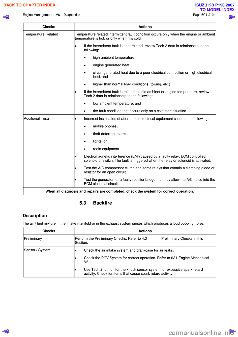
Engine Management – V6 – Diagnostics Page 6C1-2–24
Checks Actions
Temperature Related Temperature related intermittent fault condition occurs only when the engine or ambient
temperature is hot, or only when it is cold.
• If the intermittent fault is heat related, review Tech 2 data in relationship to the
following:
• high ambient temperature,
• engine generated heat,
• circuit generated heat due to a poor electrical connection or high electrical
load, and
• higher than normal load conditions (towing, etc.).
• If the intermittent fault is related to cold ambient or engine temperature, review
Tech 2 data in relationship to the following:
• low ambient temperature, and
• the fault condition that occurs only on a cold start situation.
Additional Tests
• Incorrect installation of aftermarket electrical equipment such as the following:
• mobile phones,
• theft deterrent alarms,
• lights, or
• radio equipment.
• Electromagnetic interference (EMI) caused by a faulty relay, ECM controlled
solenoid or switch. The fault is triggered when the relay or solenoid is activated.
• Test the A/C compressor clutch and some relays that contain a clamping diode or
resistor for an open circuit.
• Test the generator for a faulty rectifier bridge that may allow the A/C noise into the
ECM electrical circuit.
When all diagnosis and repairs are completed, check the system for correct operation.
5.3 Backfire
Description
The air / fuel mixture in the intake manifold or in the exhaust system ignites which produces a loud popping noise.
Checks Actions
Preliminary Perform the Preliminary Checks. Refer to 4.3 Preliminary Checks in this
Section.
Sensor / System • Check the air intake system and crankcase for air leaks.
• Check the PCV System for correct operation. Refer to 6A1 Engine Mechanical –
V6.
• Use Tech 2 to monitor the knock sensor system for excessive spark retard
activity. Check for items that cause spark retard activity.
BACK TO CHAPTER INDEX
TO MODEL INDEX
ISUZU KB P190 2007
Page 3324 of 6020
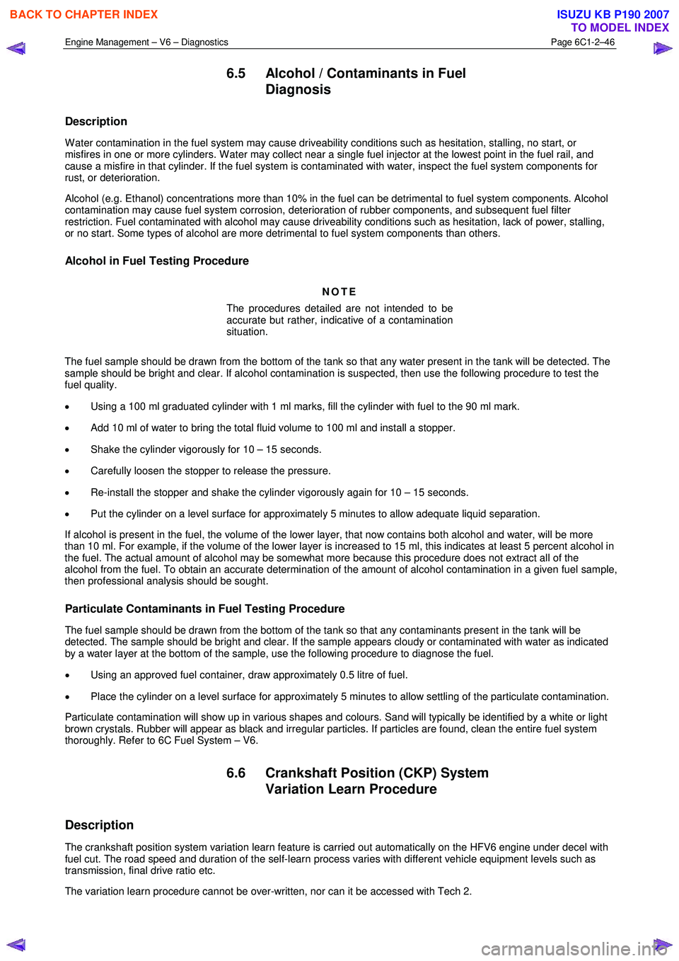
Engine Management – V6 – Diagnostics Page 6C1-2–46
6.5 Alcohol / Contaminants in Fuel
Diagnosis
Description
W ater contamination in the fuel system may cause driveability conditions such as hesitation, stalling, no start, or
misfires in one or more cylinders. W ater may collect near a single fuel injector at the lowest point in the fuel rail, and
cause a misfire in that cylinder. If the fuel system is contaminated with water, inspect the fuel system components for
rust, or deterioration.
Alcohol (e.g. Ethanol) concentrations more than 10% in the fuel can be detrimental to fuel system components. Alcohol
contamination may cause fuel system corrosion, deterioration of rubber components, and subsequent fuel filter
restriction. Fuel contaminated with alcohol may cause driveability conditions such as hesitation, lack of power, stalling,
or no start. Some types of alcohol are more detrimental to fuel system components than others.
Alcohol in Fuel Testing Procedure
NOTE
The procedures detailed are not intended to be
accurate but rather, indicative of a contamination
situation.
The fuel sample should be drawn from the bottom of the tank so that any water present in the tank will be detected. The
sample should be bright and clear. If alcohol contamination is suspected, then use the following procedure to test the
fuel quality.
• Using a 100 ml graduated cylinder with 1 ml marks, fill the cylinder with fuel to the 90 ml mark.
• Add 10 ml of water to bring the total fluid volume to 100 ml and install a stopper.
• Shake the cylinder vigorously for 10 – 15 seconds.
• Carefully loosen the stopper to release the pressure.
• Re-install the stopper and shake the cylinder vigorously again for 10 – 15 seconds.
• Put the cylinder on a level surface for approximately 5 minutes to allow adequate liquid separation.
If alcohol is present in the fuel, the volume of the lower layer, that now contains both alcohol and water, will be more
than 10 ml. For example, if the volume of the lower layer is increased to 15 ml, this indicates at least 5 percent alcohol in
the fuel. The actual amount of alcohol may be somewhat more because this procedure does not extract all of the
alcohol from the fuel. To obtain an accurate determination of the amount of alcohol contamination in a given fuel sample,
then professional analysis should be sought.
Particulate Contaminants in Fuel Testing Procedure
The fuel sample should be drawn from the bottom of the tank so that any contaminants present in the tank will be
detected. The sample should be bright and clear. If the sample appears cloudy or contaminated with water as indicated
by a water layer at the bottom of the sample, use the following procedure to diagnose the fuel.
• Using an approved fuel container, draw approximately 0.5 litre of fuel.
• Place the cylinder on a level surface for approximately 5 minutes to allow settling of the particulate contamination.
Particulate contamination will show up in various shapes and colours. Sand will typically be identified by a white or light
brown crystals. Rubber will appear as black and irregular particles. If particles are found, clean the entire fuel system
thoroughly. Refer to 6C Fuel System – V6.
6.6 Crankshaft Position (CKP) System
Variation Learn Procedure
Description
The crankshaft position system variation learn feature is carried out automatically on the HFV6 engine under decel with
fuel cut. The road speed and duration of the self-learn process varies with different vehicle equipment levels such as
transmission, final drive ratio etc.
The variation learn procedure cannot be over-written, nor can it be accessed with Tech 2.
BACK TO CHAPTER INDEX
TO MODEL INDEX
ISUZU KB P190 2007
Page 3448 of 6020
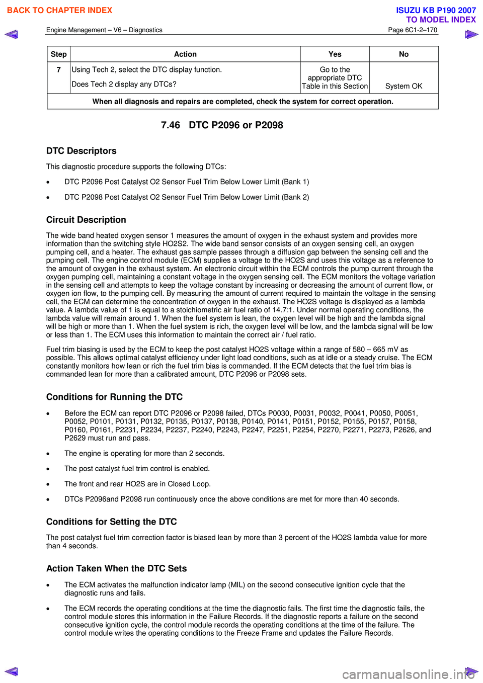
Engine Management – V6 – Diagnostics Page 6C1-2–170
Step Action Yes
No
7 Using Tech 2, select the DTC display function.
Does Tech 2 display any DTCs? Go to the
appropriate DTC
Table in this Section System OK
When all diagnosis and repairs are completed, check the system for correct operation.
7.46 DTC P2096 or P2098
DTC Descriptors
This diagnostic procedure supports the following DTCs:
• DTC P2096 Post Catalyst O2 Sensor Fuel Trim Below Lower Limit (Bank 1)
• DTC P2098 Post Catalyst O2 Sensor Fuel Trim Below Lower Limit (Bank 2)
Circuit Description
The wide band heated oxygen sensor 1 measures the amount of oxygen in the exhaust system and provides more
information than the switching style HO2S2. The wide band sensor consists of an oxygen sensing cell, an oxygen
pumping cell, and a heater. The exhaust gas sample passes through a diffusion gap between the sensing cell and the
pumping cell. The engine control module (ECM) supplies a voltage to the HO2S and uses this voltage as a reference to
the amount of oxygen in the exhaust system. An electronic circuit within the ECM controls the pump current through the
oxygen pumping cell, maintaining a constant voltage in the oxygen sensing cell. The ECM monitors the voltage variation
in the sensing cell and attempts to keep the voltage constant by increasing or decreasing the amount of current flow, or
oxygen ion flow, to the pumping cell. By measuring the amount of current required to maintain the voltage in the sensing
cell, the ECM can determine the concentration of oxygen in the exhaust. The HO2S voltage is displayed as a lambda
value. A lambda value of 1 is equal to a stoichiometric air fuel ratio of 14.7:1. Under normal operating conditions, the
lambda value will remain around 1. W hen the fuel system is lean, the oxygen level will be high and the lambda signal
will be high or more than 1. W hen the fuel system is rich, the oxygen level will be low, and the lambda signal will be low
or less than 1. The ECM uses this information to maintain the correct air / fuel ratio.
Fuel trim biasing is used by the ECM to keep the post catalyst HO2S voltage within a range of 580 – 665 mV as
possible. This allows optimal catalyst efficiency under light load conditions, such as at idle or a steady cruise. The ECM
constantly monitors how lean or rich the fuel trim bias is commanded. If the ECM detects that the fuel trim bias is
commanded lean for more than a calibrated amount, DTC P2096 or P2098 sets.
Conditions for Running the DTC
• Before the ECM can report DTC P2096 or P2098 failed, DTCs P0030, P0031, P0032, P0041, P0050, P0051,
P0052, P0101, P0131, P0132, P0135, P0137, P0138, P0140, P0141, P0151, P0152, P0155, P0157, P0158,
P0160, P0161, P2231, P2234, P2237, P2240, P2243, P2247, P2251, P2254, P2270, P2271, P2273, P2626, and
P2629 must run and pass.
• The engine is operating for more than 2 seconds.
• The post catalyst fuel trim control is enabled.
• The front and rear HO2S are in Closed Loop.
• DTCs P2096and P2098 run continuously once the above conditions are met for more than 40 seconds.
Conditions for Setting the DTC
The post catalyst fuel trim correction factor is biased lean by more than 3 percent of the HO2S lambda value for more
than 4 seconds.
Action Taken When the DTC Sets
• The ECM activates the malfunction indicator lamp (MIL) on the second consecutive ignition cycle that the
diagnostic runs and fails.
• The ECM records the operating conditions at the time the diagnostic fails. The first time the diagnostic fails, the
control module stores this information in the Failure Records. If the diagnostic reports a failure on the second
consecutive ignition cycle, the control module records the operating conditions at the time of the failure. The
control module writes the operating conditions to the Freeze Frame and updates the Failure Records.
BACK TO CHAPTER INDEX
TO MODEL INDEX
ISUZU KB P190 2007
Page 3452 of 6020
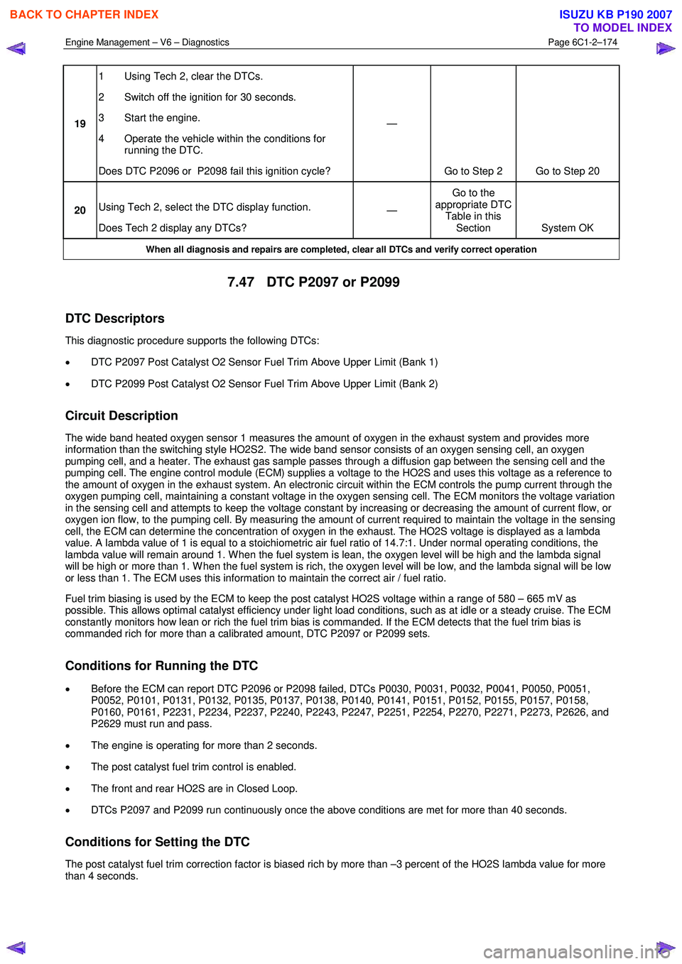
Engine Management – V6 – Diagnostics Page 6C1-2–174
19 1 Using Tech 2, clear the DTCs.
2 Switch off the ignition for 30 seconds.
3 Start the engine.
4 Operate the vehicle within the conditions for running the DTC.
Does DTC P2096 or P2098 fail this ignition cycle? —
Go to Step 2 Go to Step 20
20 Using Tech 2, select the DTC display function.
Does Tech 2 display any DTCs? —
Go to the
appropriate DTC Table in this Section System OK
When all diagnosis and repairs are completed, clear all DTCs and verify correct operation
7.47 DTC P2097 or P2099
DTC Descriptors
This diagnostic procedure supports the following DTCs:
• DTC P2097 Post Catalyst O2 Sensor Fuel Trim Above Upper Limit (Bank 1)
• DTC P2099 Post Catalyst O2 Sensor Fuel Trim Above Upper Limit (Bank 2)
Circuit Description
The wide band heated oxygen sensor 1 measures the amount of oxygen in the exhaust system and provides more
information than the switching style HO2S2. The wide band sensor consists of an oxygen sensing cell, an oxygen
pumping cell, and a heater. The exhaust gas sample passes through a diffusion gap between the sensing cell and the
pumping cell. The engine control module (ECM) supplies a voltage to the HO2S and uses this voltage as a reference to
the amount of oxygen in the exhaust system. An electronic circuit within the ECM controls the pump current through the
oxygen pumping cell, maintaining a constant voltage in the oxygen sensing cell. The ECM monitors the voltage variation
in the sensing cell and attempts to keep the voltage constant by increasing or decreasing the amount of current flow, or
oxygen ion flow, to the pumping cell. By measuring the amount of current required to maintain the voltage in the sensing
cell, the ECM can determine the concentration of oxygen in the exhaust. The HO2S voltage is displayed as a lambda
value. A lambda value of 1 is equal to a stoichiometric air fuel ratio of 14.7:1. Under normal operating conditions, the
lambda value will remain around 1. W hen the fuel system is lean, the oxygen level will be high and the lambda signal
will be high or more than 1. W hen the fuel system is rich, the oxygen level will be low, and the lambda signal will be low
or less than 1. The ECM uses this information to maintain the correct air / fuel ratio.
Fuel trim biasing is used by the ECM to keep the post catalyst HO2S voltage within a range of 580 – 665 mV as
possible. This allows optimal catalyst efficiency under light load conditions, such as at idle or a steady cruise. The ECM
constantly monitors how lean or rich the fuel trim bias is commanded. If the ECM detects that the fuel trim bias is
commanded rich for more than a calibrated amount, DTC P2097 or P2099 sets.
Conditions for Running the DTC
• Before the ECM can report DTC P2096 or P2098 failed, DTCs P0030, P0031, P0032, P0041, P0050, P0051,
P0052, P0101, P0131, P0132, P0135, P0137, P0138, P0140, P0141, P0151, P0152, P0155, P0157, P0158,
P0160, P0161, P2231, P2234, P2237, P2240, P2243, P2247, P2251, P2254, P2270, P2271, P2273, P2626, and
P2629 must run and pass.
• The engine is operating for more than 2 seconds.
• The post catalyst fuel trim control is enabled.
• The front and rear HO2S are in Closed Loop.
• DTCs P2097 and P2099 run continuously once the above conditions are met for more than 40 seconds.
Conditions for Setting the DTC
The post catalyst fuel trim correction factor is biased rich by more than –3 percent of the HO2S lambda value for more
than 4 seconds.
BACK TO CHAPTER INDEX
TO MODEL INDEX
ISUZU KB P190 2007
Page 3531 of 6020
Engine Management – V6 – Service Operations Page 6C1-3–7
Transmission – Automatic
For automatic transmission sensors and components, refer to 7C4 Automatic Transmission – 4L60E – On-vehicle
Servicing.
Transmission – Manual
For manual transmission sensors and other components, refer to 7B1 Manual Transmission – V6.
1.4 Warning Caution and Notes
This Section contains various W ARNINGS, CAUTIONS and NOTE statements that you must observe carefully to reduce
the risk of death or injury during service, repair procedures or vehicle operation. Incorrect service or repair procedures
may damage the vehicle or cause operational faults. W ARNINGS, CAUTION and NOTE statements are not exhaustive.
GM Holden LTD can not possibly warn of all the potentially hazardous consequences of failure to follow these
instructions.
Definition of WARNING, CAUTION and NOTE Statements
Diagnosis and repair procedures in this Section contain both general and specific W ARNING, CAUTION and NOTE
statements. GM Holden LTD is dedicated to the presentation of service information that helps the technician to diagnose
and repair the systems necessary for proper operation of the vehicle. Certain procedures may present a hazard to the
technician if they are not followed in the recommended manner. W ARNING, CAUTION and NOTE statements are
designed to help prevent these hazards from occurring, but not all hazards can be foreseen.
WARNING defined
A W ARNING statement immediately precedes an operating procedure or maintenance practice which, if not correctly
followed, could result in death or injury. A W ARNING statement alerts you to take necessary action or not to take a
prohibited action. If a W ARNING statement is ignored, the following consequences may occur:
• Death or injury to the technician or other personnel working on the vehicle,
• Death or injury to other people in or near the workplace area, and / or
• Death or injury to the driver / or passenger(s) of the vehicle or other people, if the vehicle has been improperly
repaired.
CAUTION defined
A CAUTION statement immediately precedes an operating procedure or maintenance practice which, if not correctly
followed, could result in damage to or destruction of equipment, or corruption of data. If a CAUTION statement is ignored,
the following consequences may occur:
• Damage to the vehicle,
• Unnecessary vehicle repairs or component replacement,
• Faulty operation or performance of any system or component being repaired,
• Damage to any system or components which depend on the proper operation of the system or component being
repaired,
• Faulty operation or performance of any systems or components which depend on the proper operation or
performance of the system or component under repair,
• Damage to fasteners, basic tools or special tools and / or
• Leakage of coolant, lubricant or other vital fluids.
NOTE defined
A NOTE statement immediately precedes or follows an operating procedure, maintenance practice or condition that
requires highlighting. A NOTE statement also emphasises necessary characteristics of a diagnostic or repair procedure.
A NOTE statement is designed to:
• Clarify a procedure,
• Present additional information for accomplishing a procedure,
BACK TO CHAPTER INDEX
TO MODEL INDEX
ISUZU KB P190 2007
Page 3572 of 6020
Engine Management – V6 – Service Operations Page 6C1-3–48
2.22 Spark Plugs
Service Precautions
1 Allow the engine to cool (to at least 50°C) before attempting to remove spark plugs. Attempting to remove spark
plugs from a hot engine may cause the plug / cylinder head threads to bind, resulting in tearing of the alloy cylinder
head threads.
2 Clean the spark plug recess area before removing any spark plug. Failure to do so could result in engine damage because of dirt or other foreign material entering the cylinder head or by the contamination of the cylinder head
threads. The contaminated threads may then prevent the correct seating of the new or replaced plug. If required,
use a thread chaser to clean the threads of any contamination where this is suspected.
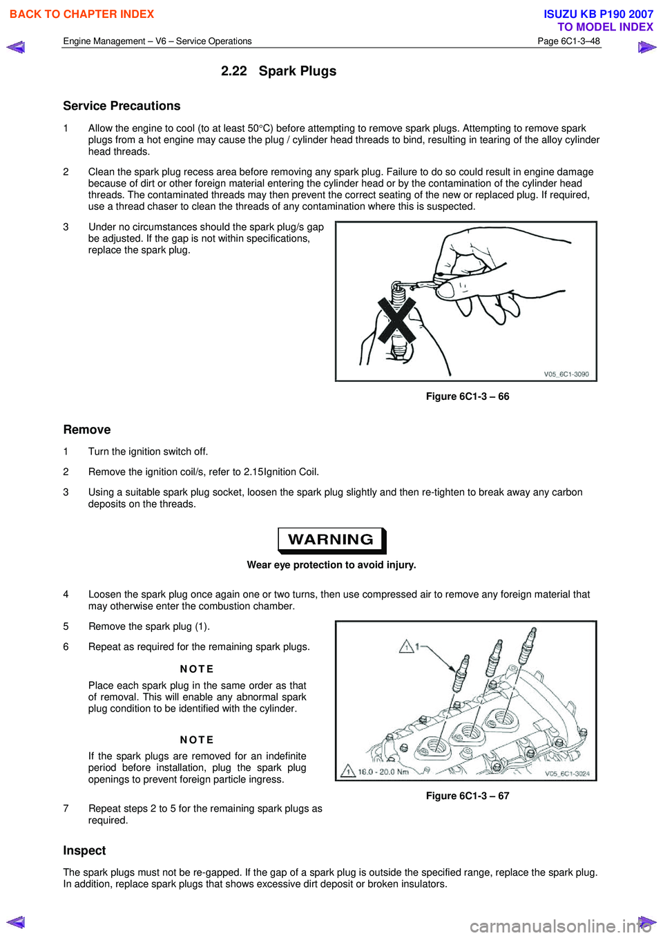
3 Under no circumstances should the spark plug/s gap be adjusted. If the gap is not within specifications,
replace the spark plug.
Figure 6C1-3 – 66
Remove
1 Turn the ignition switch off.
2 Remove the ignition coil/s, refer to 2.15 Ignition Coil.
3 Using a suitable spark plug socket, loosen the spark plug slightly and then re-tighten to break away any carbon deposits on the threads.
Wear eye protection to avoid injury.
4 Loosen the spark plug once again one or two turns, then use compressed air to remove any foreign material that may otherwise enter the combustion chamber.
5 Remove the spark plug (1).
6 Repeat as required for the remaining spark plugs.
NOTE
Place each spark plug in the same order as that
of removal. This will enable any abnormal spark
plug condition to be identified with the cylinder.
NOTE
If the spark plugs are removed for an indefinite
period before installation, plug the spark plug
openings to prevent foreign particle ingress.
7 Repeat steps 2 to 5 for the remaining spark plugs as required.
Figure 6C1-3 – 67
Inspect
The spark plugs must not be re-gapped. If the gap of a spark plug is outside the specified range, replace the spark plug.
In addition, replace spark plugs that shows excessive dirt deposit or broken insulators.
BACK TO CHAPTER INDEX
TO MODEL INDEX
ISUZU KB P190 2007
Page 3575 of 6020
Engine Management – V6 – Service Operations Page 6C1-3–51
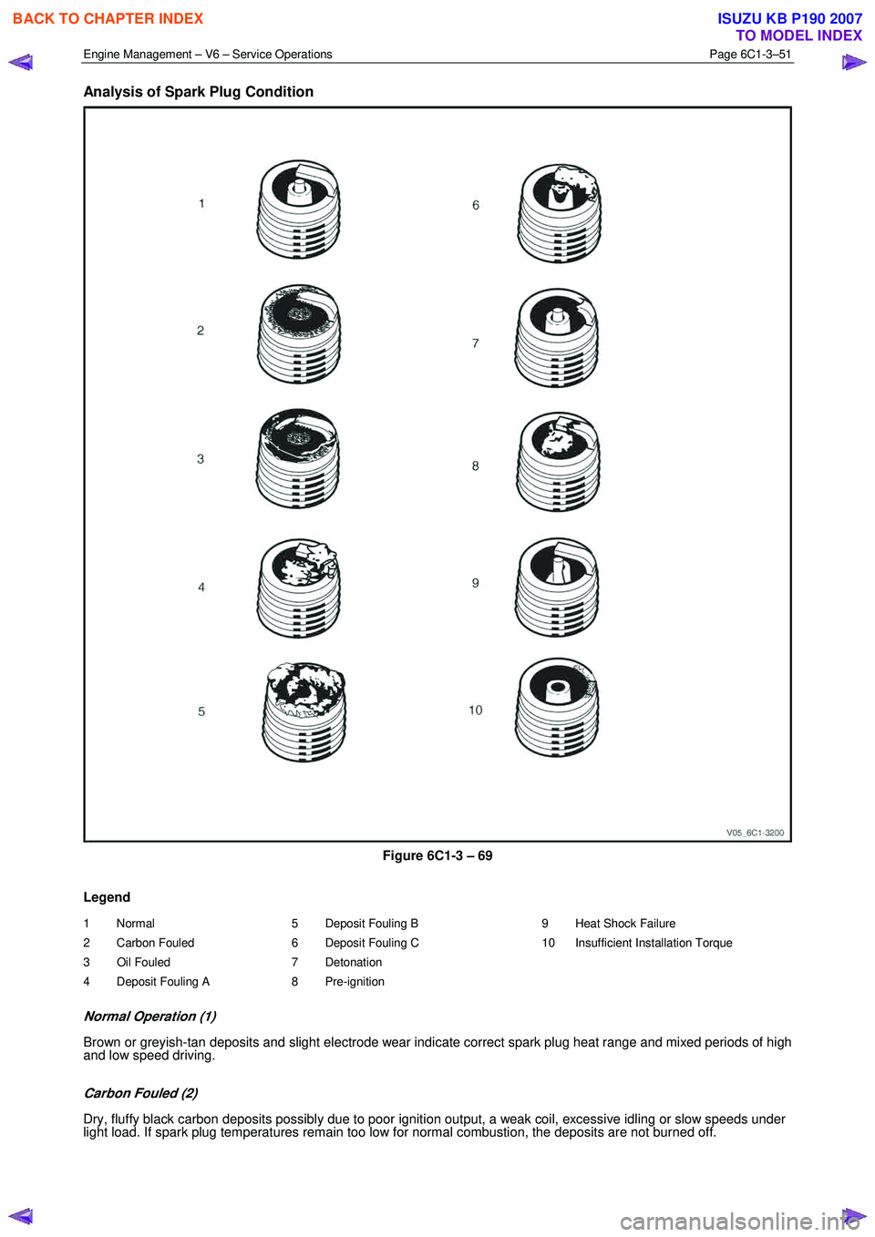
Analysis of Spark Plug Condition
Figure 6C1-3 – 69
Legend
1 Normal
2 Carbon Fouled
3 Oil Fouled
4 Deposit Fouling A 5 Deposit Fouling B
6 Deposit Fouling C
7 Detonation
8 Pre-ignition 9 Heat Shock Failure
10 Insufficient Installation Torque
Normal Operation (1)
Brown or greyish-tan deposits and slight electrode wear indicate correct spark plug heat range and mixed periods of high
and low speed driving.
Carbon Fouled (2)
Dry, fluffy black carbon deposits possibly due to poor ignition output, a weak coil, excessive idling or slow speeds under
light load. If spark plug temperatures remain too low for normal combustion, the deposits are not burned off.
BACK TO CHAPTER INDEX
TO MODEL INDEX
ISUZU KB P190 2007