2007 ISUZU KB P190 light
[x] Cancel search: lightPage 3989 of 6020
TRANSMISSION CONTROL SYSTEM (AW30–40LE) 7A2-23
Diagnostic Trouble Codes
The purpose of the “Diagnostic Trouble Codes” mode is
to display stored TCM trouble codes.
W hen “Diagnostic Trouble Codes” is selected an
“Application Menu” screen appears.
Read DTC Information
W hen “Read DTC Information” is selected, an
“Application Menu” appears with a list of DTC
information function keys addressing DTC specifics and
their origins.
Function key selections may vary for particular vehicle
and/or system.
Requested emission-related DTCs
Clear DTC Information
The purpose of the “Clear DTC Information” mode is to
command the clearing of stored TCM trouble codes.
W hen “Clear DTC Information” is selected, a “Clea
r
DTC Information”, warning screen appears. This screen
informs you that by cleaning DTC's, “all stored DTC
information in controller will be erased”.
Do you want to clear DTC's (Yes/No).
Press either the Yes or No key when answering.
After clearing codes, confirm system operation by test-
driving the vehicle.
Allow the vehicle to shift through all four forward gears
in a manner which attempts to repeat the failure
condition.
NOTE: W hen the trouble has not been repaired and
the trouble code cannot be erased, check the vehicle
again.
Data Display
The purpose of the “Data Display” mode is to
continuously monitor data parameters.
The current actual values of all important sensors and
signals in the system are displayed through F1 mode.
W hen “Data Display” is selected an “Application Menu”
appears. “Transmission Data Display”.
See “Transmission Data” on next page.
Snapshot
W hen “Snapshot” is selected an “Application Menu”
appears.
W hen “Transmission Snapshot” application is selected
from the “Application Menu”, a “Snapshot Menu”
appears, displaying several options. “Snapshot” options
may vary from one system to another.
“Snapshot” allows a recording of all vehicle parameters.
There parameters may then be replayed at a future
point in time.
This action allows you to focus on making the condition
occur, rather than trying to view all of the data in
anticipation of the fault. The snapshot will collect
parameter information around a trigger point that you
select.
W hen a snapshot is taken, it is recorded onto the
PCMCIA memory card. W hen the Tech 2 is powered
down. Snapshots are not lost.
Actuator Test
The purpose of “Actuator Test” mode is to check fo
r
correct operation of electronic system actuators.
Solenoid 2-3 Test, Solenoid 1-2/3-4 and Test TCC
Solenoid Test
You can operate the solenoids by pressing the “ON”
and “OFF” buttons.
Preconditions: P–N position, no vehicle speed, no
engine speed
Pressure Control Solenoid (PCS)
You can set desired PCS Current using the “ON” and
“OFF” button. The PCS Data informs about PCS
Current, Pressure and Duty Cycle.
Preconditions: P–N position, no engine speed, no
vehicle speed
3rd Start Lamp Test, Power Lamp Test, AT Oil
Temperature Lamp Test and Check Light Test
You can operate the lamps by pressing the “ON” and
“OFF” buttons.
Preconditions: none
NOTE: Freeze Frame
Freeze Frame is an element of the Diagnostic
Management System which stores various vehicle
information at the moment an emission-related fault
is stored in memory and when the Check Trans
Lamp is commanded on. These data can help to
identity the cause of a fault. Refer to Storing An
d
Erasing Freeze Frame Data for more detaile
d
information.
BACK TO CHAPTER INDEX
TO MODEL INDEX
ISUZU KB P190 2007
Page 3990 of 6020
7A2-24 TRANSMISSION CONTROL SYSTEM (AW30–40LE)
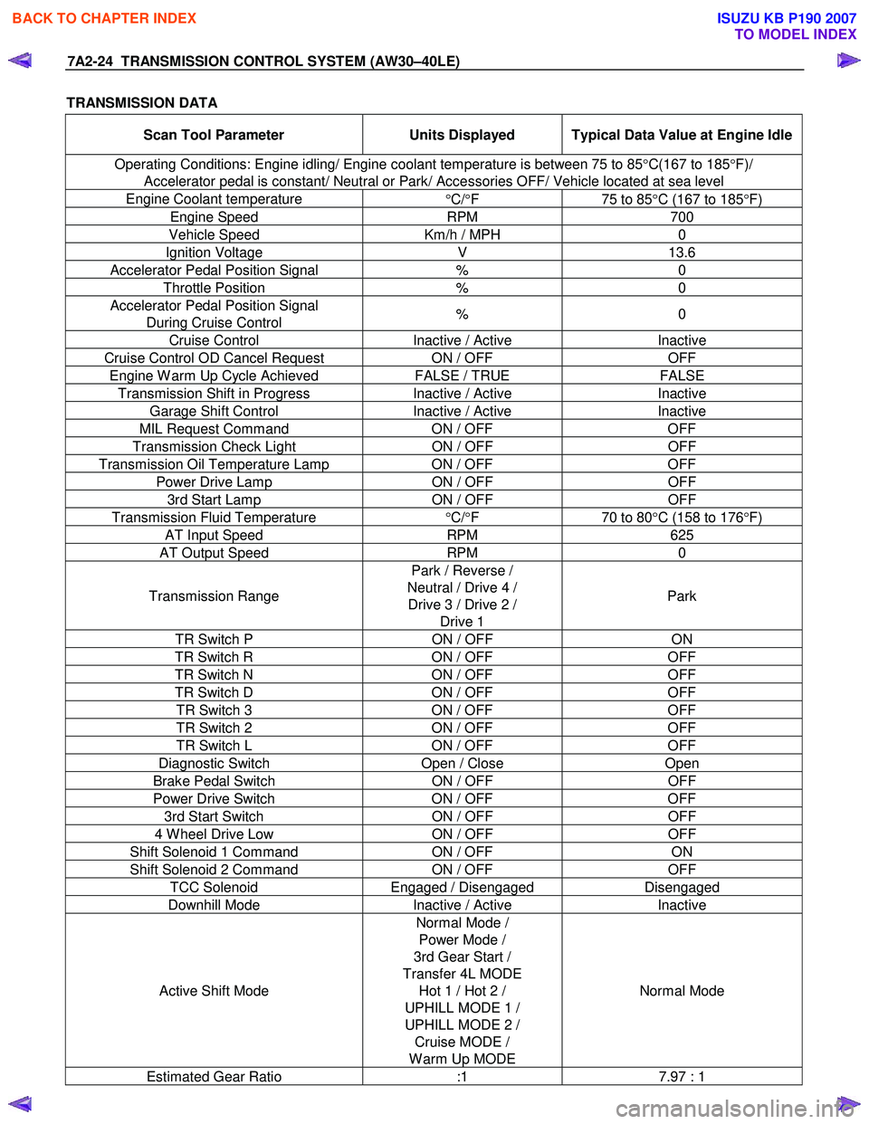
TRANSMISSION DATA
Scan Tool Parameter Units Displayed Typical Data Value at Engine Idle
Operating Conditions: Engine idling/ Engine coolant temperature is between 75 to 85 °C(167 to 185 °F)/
Accelerator pedal is constant/ Neutral or Park/ Accessories OFF/ Vehicle located at sea level
Engine Coolant temperature °C/ °F 75 to 85°C (167 to 185 °F)
Engine Speed RPM 700
Vehicle Speed Km/h / MPH 0
Ignition Voltage V 13.6
Accelerator Pedal Position Signal % 0
Throttle Position % 0
Accelerator Pedal Position Signal
During Cruise Control % 0
Cruise Control
Inactive / Active Inactive
Cruise Control OD Cancel Request ON / OFF OFF
Engine W arm Up Cycle Achieved FALSE / TRUE FALSE
Transmission Shift in Progress Inactive / Active Inactive
Garage Shift Control Inactive / Active Inactive
MIL Request Command ON / OFF OFF
Transmission Check Light ON / OFF OFF
Transmission Oil Temperature Lamp ON / OFF OFF
Power Drive Lamp ON / OFF OFF
3rd Start Lamp ON / OFF OFF
Transmission Fluid Temperature
°C/ °F 70 to 80°C (158 to 176 °F)
AT Input Speed RPM 625
AT Output Speed RPM 0
Transmission Range Park / Reverse /
Neutral / Drive 4 / Drive 3 / Drive 2 / Drive 1 Park
TR Switch P
ON / OFF ON
TR Switch R ON / OFF OFF
TR Switch N ON / OFF OFF
TR Switch D ON / OFF OFF
TR Switch 3 ON / OFF OFF
TR Switch 2 ON / OFF OFF
TR Switch L ON / OFF OFF
Diagnostic Switch Open / Close Open
Brake Pedal Switch ON / OFF OFF
Power Drive Switch ON / OFF OFF
3rd Start Switch ON / OFF OFF
4 W heel Drive Low ON / OFF OFF
Shift Solenoid 1 Command ON / OFF ON
Shift Solenoid 2 Command ON / OFF OFF
TCC Solenoid Engaged / Disengaged Disengaged
Downhill Mode Inactive / Active Inactive
Active Shift Mode Normal Mode /
Power Mode /
3rd Gear Start /
Transfer 4L MODE Hot 1 / Hot 2 /
UPHILL MODE 1 /
UPHILL MODE 2 / Cruise MODE /
W arm Up MODE Normal Mode
Estimated Gear Ratio
:1 7.97 : 1
BACK TO CHAPTER INDEX
TO MODEL INDEX
ISUZU KB P190 2007
Page 4007 of 6020
TRANSMISSION CONTROL SYSTEM (AW30–40LE) 7A2-41
• All of the following conditions are met.
- Device Control is not operating
- Disable Normal Communication Service is receiving enable
- DTC Clear is not operating
Condition For Setting The DTC
W hen the TCM detects following conditions at 20 times
continuously.
• Ignition voltage is less than 9 volts for 1 second o
r
more continuously. (DTC P0562)
• Ignition voltage is more than 18 volts for 1 second o
r
more continuously. (DTC P0563)
Action Taken When The DTC Sets
• DTC stored.
Conditions For Clearing The DTC
• The DTC can be cleared from the TCM history by
using a scan tool.
• The DTC will be cleared from history when the
vehicle has achieved 40 warm-up cycles without a
failure reported.
•
After more than 1 second has elapsed after the
ignition key has been turned “ON”, short between
No.11 and No.4 (ground) of DLC (Data Link
Connector). Then, after 1 second, but within 6
seconds, discontinue shorting.
Diagnostic Aids
•
Inspect the wiring for poor electrical connection at the
TCM. Look for possible bent, backed out, deformed
or damaged terminals. Check for weak terminal
tension as well. Also check for a chafed wire that
could short to bare metal or other wiring.
Inspect for a broken wire inside the insulation.
• W hen diagnosing for a possible intermittent short o
r
open condition, move the wiring harness while
observing test equipment for a change.
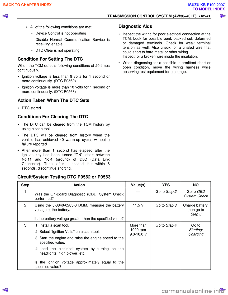
Circuit/System Testing DTC P0562 or P0563
Step Action Value(s) YES NO
1
W as the On-Board Diagnostic (OBD) System Check
performed? — Go to
Step 2 Go to OBD
System Check
2 Using the 5-8840-0285-0 DMM, measure the battery voltage at the battery.
Is the battery voltage greater than the specified value? 11.5 V Go to
Step 3 Charge battery,
then go to Step 3
3 1. Install a scan tool.
2. Select “Ignition Volts” on a scan tool.
3. Start the engine and raise the engine speed to the specified value.
4. Load the electrical system by turning on the headlights, high blower, etc.
Is the ignition voltage approximately equal to the
specified value? More than
1000 rpm
9.0-18.0 V Go to
Step 4 Go to
Starting/
Charging
BACK TO CHAPTER INDEX
TO MODEL INDEX
ISUZU KB P190 2007
Page 4106 of 6020
ON-VEHICLE SERVICE (AW30–40LE) 7A3-21
Brake Signal
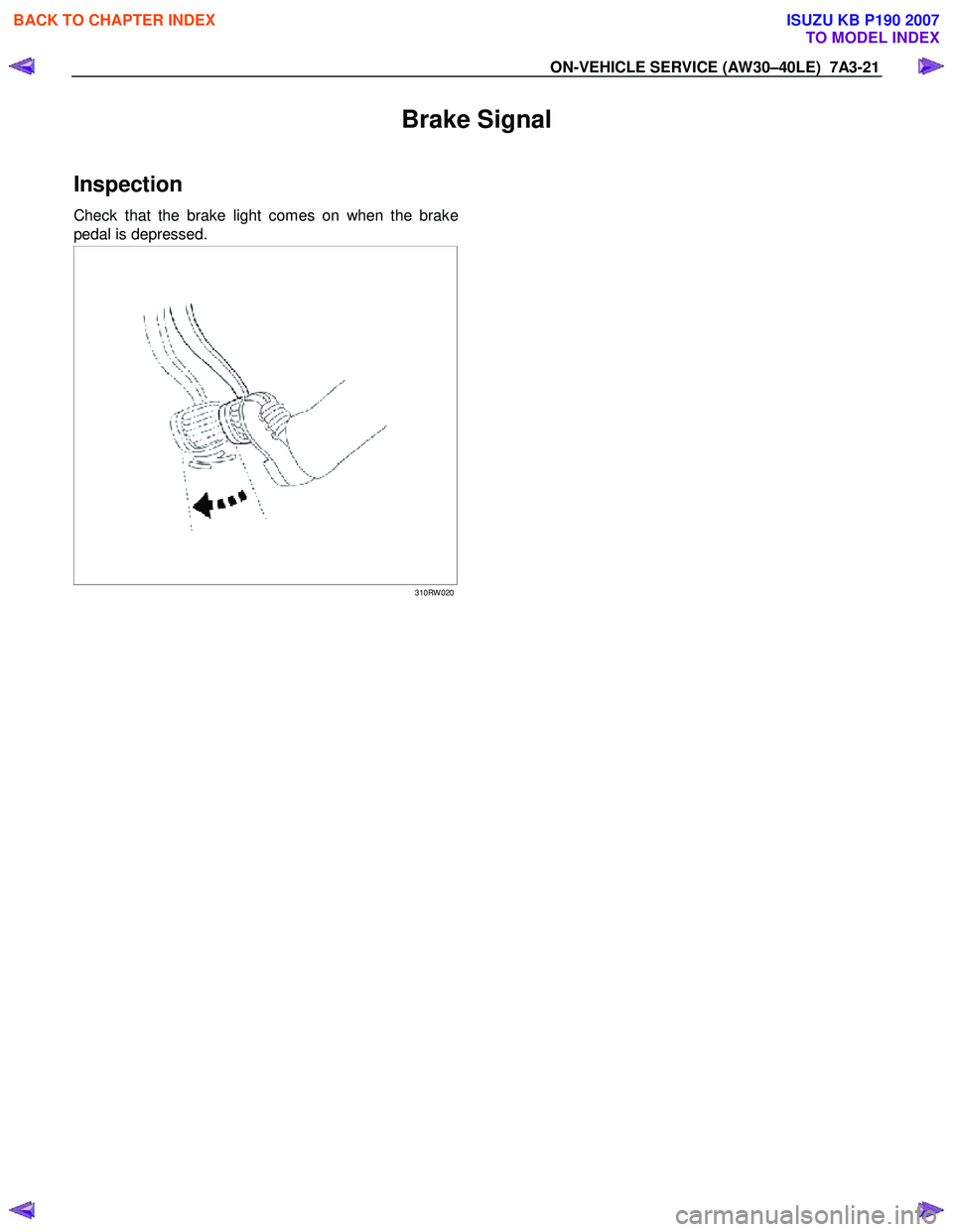
Inspection
Check that the brake light comes on when the brake
pedal is depressed.
310RW 020
BACK TO CHAPTER INDEX
TO MODEL INDEX
ISUZU KB P190 2007
Page 4170 of 6020
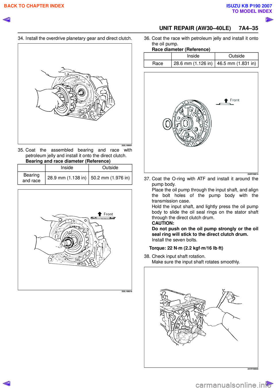
UNIT REPAIR (AW30–40LE) 7A4–35
34. Install the overdrive planetary gear and direct clutch.
252L100001
35. Coat the assembled bearing and race withpetroleum jelly and install it onto the direct clutch.
Bearing and race diameter (Reference)
252L100018
36. Coat the race with petroleum jelly and install it onto the oil pump.
Race diameter (Reference)
252RY00014
37. Coat the O-ring with ATF and install it around the pump body.
Place the oil pump through the input shaft, and align
the bolt holes of the pump body with the
transmission case.
Hold the input shaft, and lightly press the oil pump
body to slide the oil seal rings on the stator shaft
through the direct clutch drum.
CAUTION:
Do not push on the oil pump strongly or the oil
seal ring will stick to the direct clutch drum.
Install the seven bolts.
Torque: 22 N ·m (2.2 kgf ·m/16 lb ·ft)
38. Check input shaft rotation. Make sure the input shaft rotates smoothly.
241RY00003
Inside Outside
Bearing
and race 28.9 mm (1.138 in) 50.2 mm (1.976 in)
Inside
Outside
Race 28.6 mm (1.126 in) 46.5 mm (1.831 in)
BACK TO CHAPTER INDEX
TO MODEL INDEX
ISUZU KB P190 2007
Page 4256 of 6020
CONSTRUCTION AND FUNCTION 7A1-17
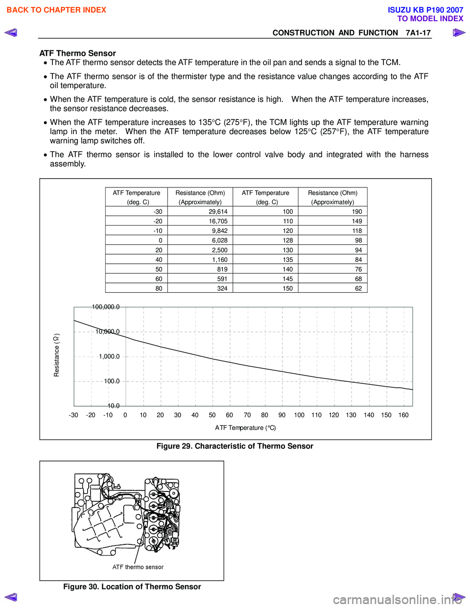
ATF Thermo Sensor • The ATF thermo sensor detects the ATF temperature in the oil pan and sends a signal to the TCM.
• The ATF thermo sensor is of the thermister type and the resistance value changes according to the ATF
oil temperature.
• When the ATF temperature is cold, the sensor resistance is high. When the ATF temperature increases,
the sensor resistance decreases.
• When the ATF temperature increases to 135 °C (275 °F), the TCM lights up the ATF temperature warning
lamp in the meter. When the ATF temperature decreases below 125 °C (257 °F), the ATF temperature
warning lamp switches off.
• The ATF thermo sensor is installed to the lower control valve body and integrated with the harness
assembly.
10.0
100.0
1,000.0
10,000.0
100,000.0
-30 -20 -10 0 10 20 30 40 50 60 70 80 90 100 110 120 130 140 150 160 A TF Temp er a t ur e ( °C)
Resistance (Ω
)
Figure 29. Characteristic of Thermo Sensor
Figure 30. Location of Thermo Sensor
ATF Temperature
(deg. C) Resistance (Ohm)
(Approximately) ATF Temperature
(deg. C) Resistance (Ohm)
(Approximately)
-30 29,614 100190
-20 16,705 110149
-10 9,842 120118
0 6,028 128 98
20 2,500 130 94
40 1,160 135 84
50 819 140 76
60 591 14568
80 324 15062
BACK TO CHAPTER INDEX
TO MODEL INDEX
ISUZU KB P190 2007
Page 4311 of 6020
TRANSMISSION CONTROL SYSTEM (JR405E) 7A2-27
Power Drive Switch
This parameter displays the input state of the power
drive switch to the TCM. When the switch is pressed,
the scan tool displays On.
Power Drive Lamp
This parameter displays the commanded state of the
power drive lamp control circuit. The lamp should be
On when the scan tool indicates command On.
Brake Pedal Switch
This parameter displays the input state of the brake
pedal switch to the TCM. When the pedal is depressed,
scan tool displays On. Diagnostic Switch
This parameter displays the input state of the
diagnostic request switch to the TCM. When the data
link connector (DLC) terminal 11 is pulled low, the
check trans lamp blinks to indicate flash code.
Check Trans Lamp
This parameter displays the commanded state of the
check trans lamp control circuit. The lamp should be
On when the scan tool indicates command On.
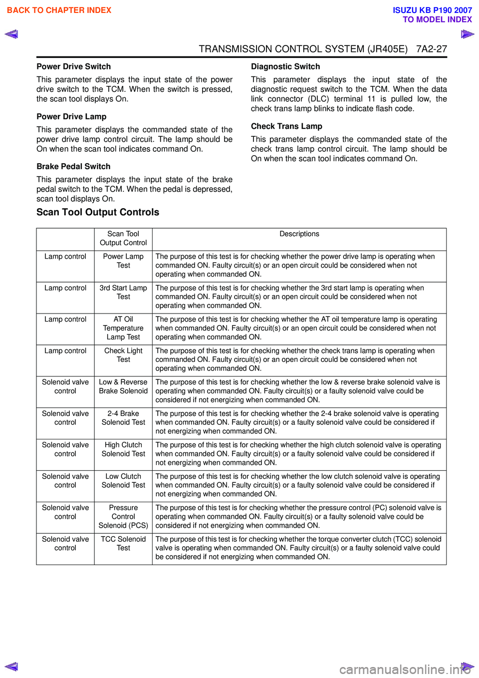
Scan Tool Output Controls
Scan Tool
Output Control Descriptions
Lamp control Power Lamp Te s tThe purpose of this test is for checking whether the power drive lamp is operating when
commanded ON. Faulty circuit(s) or an open circuit could be considered when not
operating when commanded ON.
Lamp control 3rd Start Lamp Te s t The purpose of this test is for checking whether the 3rd start lamp is operating when
commanded ON. Faulty circuit(s) or an open circuit could be considered when not
operating when commanded ON.
Lamp control AT Oil Temperature
Lamp Test The purpose of this test is for checking whether the AT oil temperature lamp is operating
when commanded ON. Faulty circuit(s) or an open circuit could be considered when not
operating when commanded ON.
Lamp control Check Light Te s t The purpose of this test is for checking whether the check trans lamp is operating when
commanded ON. Faulty circuit(s) or an open circuit could be considered when not
operating when commanded ON.
Solenoid valve control Low & Reverse
Brake Solenoid The purpose of this test is for checking whether the low & reverse brake solenoid valve is
operating when commanded ON. Faulty circuit(s) or a faulty solenoid valve could be
considered if not energizing when commanded ON.
Solenoid valve control 2-4 Brake
Solenoid Test The purpose of this test is for checking whether the 2-4 brake solenoid valve is operating
when commanded ON. Faulty circuit(s) or a faulty solenoid valve could be considered if
not energizing when commanded ON.
Solenoid valve control High Clutch
Solenoid Test The purpose of this test is for checking whether the high clutch solenoid valve is operating
when commanded ON. Faulty circuit(s) or a faulty solenoid valve could be considered if
not energizing when commanded ON.
Solenoid valve control Low Clutch
Solenoid Test The purpose of this test is for checking whether the low clutch solenoid valve is operating
when commanded ON. Faulty circuit(s) or a faulty solenoid valve could be considered if
not energizing when commanded ON.
Solenoid valve control Pressure
Control
Solenoid (PCS) The purpose of this test is for checking whether the pressure control (PC) solenoid valve is
operating when commanded ON. Faulty circuit(s) or a faulty solenoid valve could be
considered if not energizing when commanded ON.
Solenoid valve control TCC Solenoid
Te s t The purpose of this test is for checking whether the torque converter clutch (TCC) solenoid
valve is operating when commanded ON. Faulty circuit(s) or a faulty solenoid valve could
be considered if not energizing when commanded ON.
BACK TO CHAPTER INDEX
TO MODEL INDEX
ISUZU KB P190 2007
Page 4317 of 6020
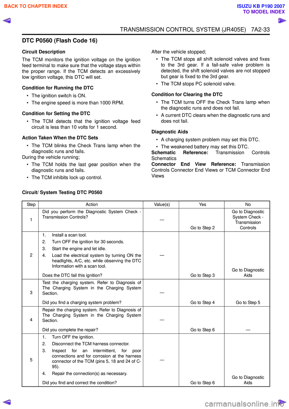
TRANSMISSION CONTROL SYSTEM (JR405E) 7A2-33
DTC P0560 (Flash Code 16)
Circuit Description
The TCM monitors the ignition voltage on the ignition
feed terminal to make sure that the voltage stays within
the proper range. If the TCM detects an excessively
low ignition voltage, this DTC will set.
Condition for Running the DTC • The ignition switch is ON.
• The engine speed is more than 1000 RPM.
Condition for Setting the DTC • The TCM detects that the ignition voltage feed circuit is less than 10 volts for 1 second.
Action Taken When the DTC Sets • The TCM blinks the Check Trans lamp when the diagnostic runs and fails.
During the vehicle running;
• The TCM holds the last gear position when the diagnostic runs and fails.
• The TCM inhibits lock up control. After the vehicle stopped;
• The TCM stops all shift solenoid valves and fixes to the 3rd gear. If a fail-safe valve problem is
detected, the shift solenoid valves are not stopped
but gear is fixed to the 3rd gear.
• The TCM stops PC solenoid valve.
Condition for Clearing the DTC • The TCM turns OFF the Check Trans lamp when the diagnostic runs and does not fail.
• A current DTC clears when the diagnostic runs and does not fail.
Diagnostic Aids • A charging system problem may set this DTC.
• The weakened battery may set this DTC.
Schematic Reference: Transmission Controls
Schematics
Connector End View Reference: Transmission
Controls Connector End Views or TCM Connector End
Views
Circuit/ System Testing DTC P0560
Step Action Value(s)Yes No
1 Did you perform the Diagnostic System Check -
Transmission Controls? —
Go to Step 2 Go to Diagnostic
System Check -
Transmission Controls
2 1. Install a scan tool.
2. Turn OFF the ignition for 30 seconds.
3. Start the engine and let idle.
4. Load the electrical system by turning ON the headlights, A/C, etc. while observing the DTC
Information with a scan tool.
Does the DTC fail this ignition? —
Go to Step 3 Go to Diagnostic
Aids
3 Test the charging system. Refer to Diagnosis of
The Charging System in the Charging System
Section.
Did you find a charging system problem? —
Go to Step 4 Go to Step 5
4 Repair the charging system. Refer to Diagnosis of
The Charging System in the Charging System
Section.
Did you complete the repair? —
Go to Step 6 —
5 1. Turn OFF the ignition.
2. Disconnect the TCM harness connector.
3. Inspect for an intermittent, for poor connections and for corrosion at the harness
connector of the TCM (pins 5, 18 and 24 of C-
95).
4. Repair the connection(s) as necessary.
Did you find and correct the condition? —
Go to Step 6 Go to Diagnostic
Aids
BACK TO CHAPTER INDEX
TO MODEL INDEX
ISUZU KB P190 2007