Page 4426 of 6020
7A2-142 TRANSMISSION CONTROL SYSTEM (JR405E)
• Select Programming Process - Identifywhether as existing TCM is being
reprogrammed or an TCM is being replaced
with a new one.
• Select ECU Location - Vehicle
4. Complete all vehicle data on the Preparing for Communication/ Determine Vehicle screen until
“Next” is highlighted, then click “Next”.
5. Follow the instruction on the Preparing for Communication screen, then click “Next”.
Notice: In order to reduce the potential for signal loss,
the RS-232 cable should not be more than 25 feet long.
6. Verify the VIN on the Validate Vehicle Identification Number (VIN) screen, then click “Next”.
Notice: If the TCM is replaced to new one, VIN does
not displayed. Input correct VIN reading from stamped
VIN or affixed VIN plate on the vehicle. If the TCM from
another vehicle is installed, input correct VIN by same
way.
7. Highlight Transmission on the Select System Type screen, then click “Next”, if on-screen instruction
displayed.
8. Complete the following information based on the service ID plate on the Validate Vehicle Data
screen until “Next” is highlighted, then click “Next”.
• Model
• Model year
• Engine type
• Model designator
• Destination code
• Transmission type
9. Verify your selection on the Summary screen.
Notice: Refer to Service Bulletin and Description
column before service programming is performed if the
bulletins are listed along with the calibration files.
Notice: Select Cancel if you receive a message stating
that the calibration selected is already the current
calibration in the TCM and reprogramming with the
same download is not allowed.
10. Click “Reprog”.
11. The Transfer Data screen will appear until the progress bar reaches 100%.
Notice: Some warning lamp may turn ON or blink while
programming the TCM since communication between
the TCM and other modules are interrupted. Clear DTC
in any module after programming.
12. Close the application and return to the TIS application selection screen after the download is
completed.
13. Turn OFF the ignition.
14. Turn OFF the scan tool and disconnect from the vehicle.
BACK TO CHAPTER INDEX
TO MODEL INDEX
ISUZU KB P190 2007
Page 4475 of 6020
ON-VEHICLE SERVICE (JR405E) 7A3-21
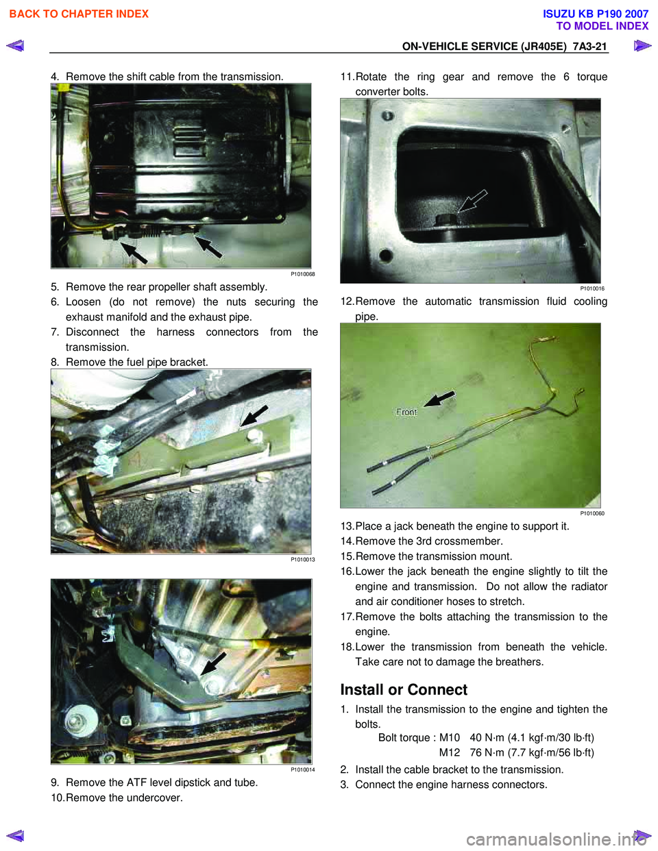
4. Remove the shift cable from the transmission.
P1010068
5. Remove the rear propeller shaft assembly.
6. Loosen (do not remove) the nuts securing the exhaust manifold and the exhaust pipe.
7. Disconnect the harness connectors from the transmission.
8. Remove the fuel pipe bracket.
P1010013
P1010014
9. Remove the ATF level dipstick and tube.
10. Remove the undercover.
11. Rotate the ring gear and remove the 6 torque
converter bolts.
P1010016
12. Remove the automatic transmission fluid cooling pipe.
P1010060
13. Place a jack beneath the engine to support it.
14. Remove the 3rd crossmember.
15. Remove the transmission mount.
16. Lower the jack beneath the engine slightly to tilt the engine and transmission. Do not allow the radiato
r
and air conditioner hoses to stretch.
17. Remove the bolts attaching the transmission to the engine.
18. Lower the transmission from beneath the vehicle. Take care not to damage the breathers.
Install or Connect
1. Install the transmission to the engine and tighten the bolts.
Bolt torque : M10 40 N·m (4.1 kgf·m/30 lb·ft)
M12 76 N·m (7.7 kgf·m/56 lb·ft)
2. Install the cable bracket to the transmission.
3. Connect the engine harness connectors.
BACK TO CHAPTER INDEX
TO MODEL INDEX
ISUZU KB P190 2007
Page 4479 of 6020
7A4-2 UNIT REPAIR (JR405E)
AUTOMATIC TRANSMISSION
DISASSEMBLY
Cleaning the automatic transmission
1. Use compressed steam and /or cleaning oil to thoroughly
clean the outside of the transmission before disassembly.
CAUTION:
Steam under high pressure may cause dirt particles
adhering to the transmission to fly through the air at great
speed. These particles can cause serious eye injury. Wear
protective goggles when steam-cleaning the outside of
the transmission.
2. During disassembly, clean the removed parts with cleaning oil. Dry the parts with compressed air.
Use Compressed air to clean the transmission oil holes
and oil passages.
Automatic transmission disassembly cautions
• Perform the disassembly procedure in a dust-free
environment to prevent the entry of foreign material into
the transmission.
• Inspect each transmission part as you remove it.
• Carefully check the oil pan and the magnet for foreign
material. This is a good way to estimate the transmission
condition.
• Use your bare hands or vinyl gloves to disassemble the
transmission. Do not use ordinary work gloves (loose
threads from the gloves may fall into the transmission and
cause problems).
• Use a plastic hammer to loosen the transmission case
and other aluminum parts during disassembly. Strike
around the parts lightly with the hammer. Do not pry
aluminum parts away from each other with a screwdriver
or similar object.
• Arrange the disassembled parts neatly in the order they
were removed. Cover the parts with a plastic sheet or
similar object to protect them from dust.
BACK TO CHAPTER INDEX
TO MODEL INDEX
ISUZU KB P190 2007
Page 4572 of 6020
7B-8 MSG MODEL
Exhaust Pipe
1. Remove the exhaust pipe bracket from the transmission
case.
2. Remove the exhaust pipe.
Rear Propeller Shaft (Dual Shaft Type)
1. Apply setting marks to the 2nd propeller shaft flange yoke.
This will prevent mispositioning during the installation procedure.
2. Remove the 2nd propeller shaft flange yoke nuts at the drive pinion side
1.
3. Remove the center bearing retainer bolts
2 .
4. Remove the 1st propeller shaft with the center bearing and the 2nd propeller shaft.
Pull the 1st propeller shaft toward the rear of the vehicle until the spline yoke is free of the transmission main shaft.
Harness Connector
Disconnect the back up light switch connector and the
speedometer sensor connector.
Slave Cylinder
Remove the slave cylinder from the transmission case.
BACK TO CHAPTER INDEX
TO MODEL INDEX
ISUZU KB P190 2007
Page 4577 of 6020
MSG MODEL 7B-13
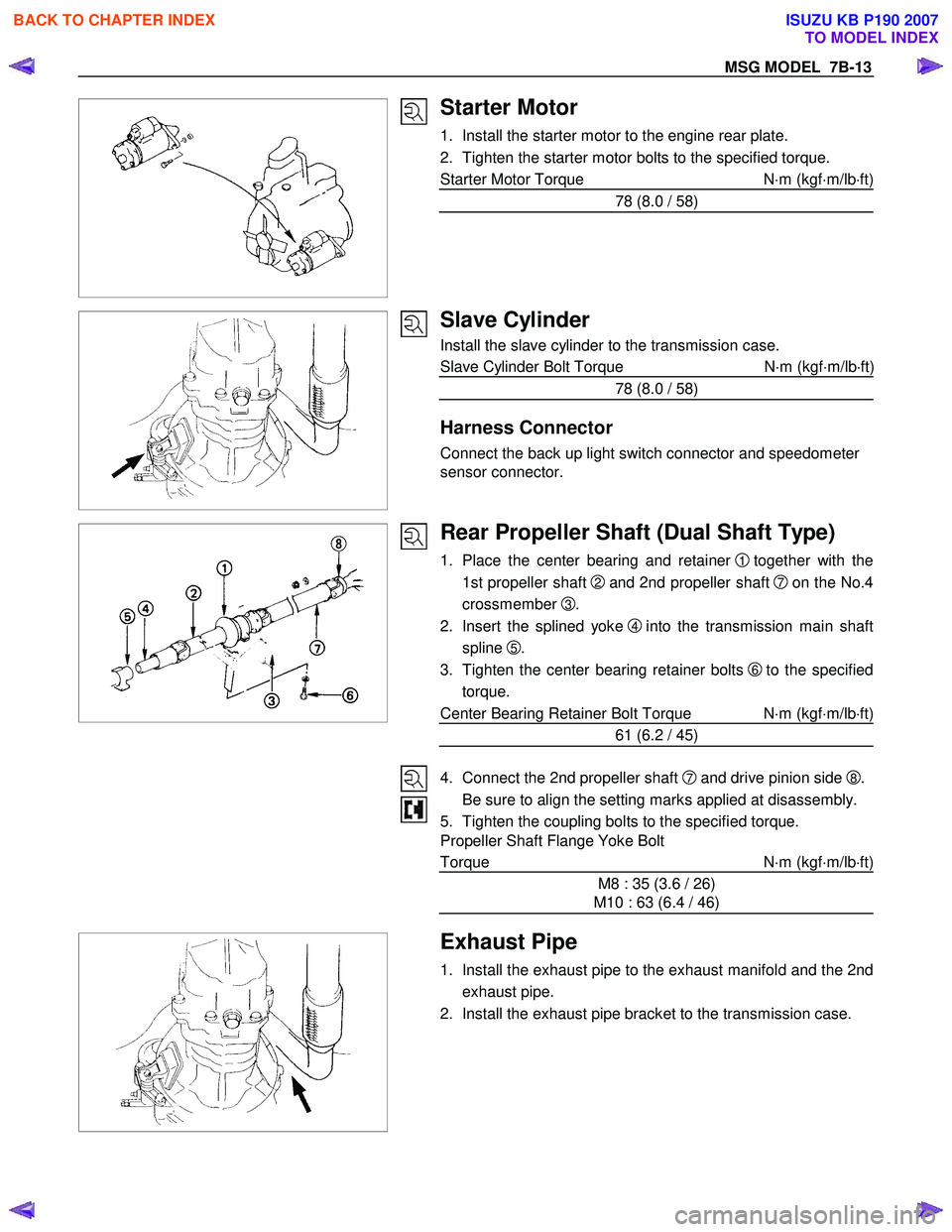
Starter Motor
1. Install the starter motor to the engine rear plate.
2. Tighten the starter motor bolts to the specified torque.
Starter Motor Torque N⋅m (kgf ⋅m/lb ⋅ft)
78 (8.0 / 58)
Slave Cylinder
Install the slave cylinder to the transmission case.
Slave Cylinder Bolt Torque N ⋅m (kgf ⋅m/lb ⋅ft
)
78 (8.0 / 58)
Harness Connector
Connect the back up light switch connector and speedometer
sensor connector.
Rear Propeller Shaft (Dual Shaft Type)
1. Place the center bearing and retainer 1 together with the
1st propeller shaft
2 and 2nd propeller shaft 7on the No.4
crossmember
3.
2. Insert the splined yoke
4 into the transmission main shaft
spline
5.
3. Tighten the center bearing retainer bolts
6 to the specified
torque.
Center Bearing Retainer Bolt Torque N ⋅m (kgf ⋅m/lb ⋅ft)
61 (6.2 / 45)
4. Connect the 2nd propeller shaft
7 and drive pinion side 8.
Be sure to align the setting marks applied at disassembly.
5. Tighten the coupling bolts to the specified torque.
Propeller Shaft Flange Yoke Bolt
Torque N ⋅m (kgf ⋅m/lb ⋅ft)
M8 : 35 (3.6 / 26)
M10 : 63 (6.4 / 46)
Exhaust Pipe
1. Install the exhaust pipe to the exhaust manifold and the 2nd
exhaust pipe.
2. Install the exhaust pipe bracket to the transmission case.
BACK TO CHAPTER INDEX
TO MODEL INDEX
ISUZU KB P190 2007
Page 4596 of 6020
7B-32 MSG MODEL
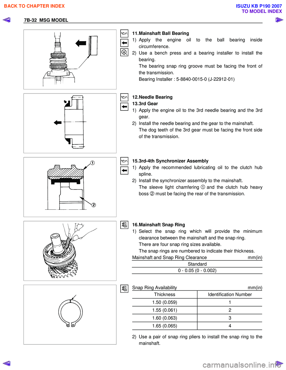
11. Mainshaft Ball Bearing
1) Apply the engine oil to the ball bearing inside circumference.
2) Use a bench press and a bearing installer to install the bearing.
The bearing snap ring groove must be facing the front o
f
the transmission.
Bearing Installer : 5-8840-0015-0 (J-22912-01)
12. Needle Bearing
13. 3rd Gear
1) Apply the engine oil to the 3rd needle bearing and the 3rd
gear.
2) Install the needle bearing and the gear to the mainshaft.
The dog teeth of the 3rd gear must be facing the front side of the transmission.
15. 3rd-4th Synchronizer Assembly
1)
Apply the recommended lubricating oil to the clutch hub
spline.
2) Install the synchronizer assembly to the mainshaft.
The sleeve light chamfering
1 and the clutch hub heavy
boss
2 must be facing the rear of the transmission.
16. Mainshaft Snap Ring
1) Select the snap ring which will provide the minimum clearance between the mainshaft and the snap ring.
There are four snap ring sizes available.
The snap rings are numbered to indicate their thickness.
Mainshaft and Snap Ring Clearance mm(in)
Standard
0 - 0.05 (0 - 0.002)
Snap Ring Availability
mm(in)
Thickness Identification Number
1.50 (0.059) 1
1.55 (0.061)2
1.60 (0.063)3
1.65 (0.065)4
2) Use a pair of snap ring pliers to install the snap ring to the
mainshaft.
BACK TO CHAPTER INDEX
TO MODEL INDEX
ISUZU KB P190 2007
Page 4798 of 6020
7C-20 CLUTCH
SERVICING
Servicing refers to general maintenance procedures to be performed by qualified service personnel.
CLUTCH PEDAL PLAY
Inspection
Depress the clutch pedal lightly by hand, and measure to
determine if the free play is within the standard value.
Pedal Free Play mm(in)
H 5.0-15.0 (0.2-0.6)
Adjustment of the clutch switch (or stopper bolt)
Turn the clutch switch or stopper bolt 1 until the switch bolt
or
stopper bolt just touches the clutch pedal arm.
Adjust clutch switch or stopper bolt
by backing it out half a turn,
and measure the clearance (L) between the clutch pedal arm
and the clutch switch bolt end or stopper bolt.
Lock the lock nut
2.
Connect clutch switch connector.
Clutch switch and clutch pedal
Clearance mm(in)
(L) 0.5-1.5 (0.020-0.059)
BACK TO CHAPTER INDEX
TO MODEL INDEX
ISUZU KB P190 2007
Page 4842 of 6020
7D-12 TRANSFER CASE
Removal
NOTE: Before removing transmission and transfer
assembly from vehicle, change the transfer mode to
2W D using the 4W D push button switch on dash panel.
1. Disconnect battery ground cable.
2. Raise and support vehicle with suitable stands. Drain
transfer case fluid.
3. Remove rear propeller shaft and front propeller shaft.
NOTE: Apply alignment marks on the flange at both front
and rear sides.
4. Disconnect harness connectors and clip.
Connector: transfer switch, 2W D-4W D actuator,
speed sensor.
NOTE: Avoid turning the vehicle ignition switch to the ON
position when the 2W D-4W D connector is removed
(battery connected).
If the ignition switch must be turned to the ON position,
the controller must first be removed (memory must be
cleared because the CHECK 4W D INDICATOR will
light).
5. Remove transfer case assembly from the vehicle.
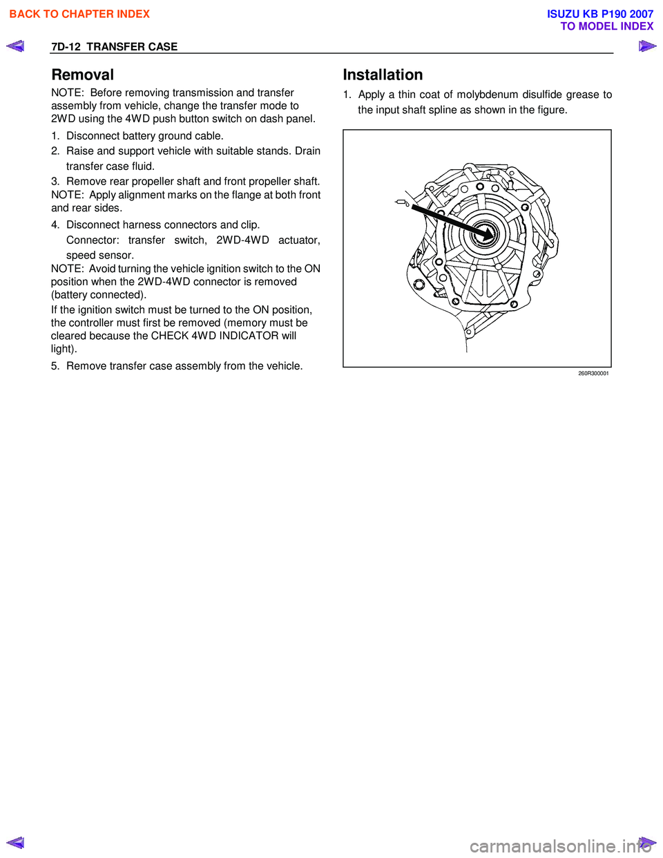
Installation
1. Apply a thin coat of molybdenum disulfide grease to
the input shaft spline as shown in the figure.
260R300001
BACK TO CHAPTER INDEX
TO MODEL INDEX
ISUZU KB P190 2007