2007 ISUZU KB P190 light
[x] Cancel search: lightPage 4894 of 6020
7D1-20 TRANSFER CONTROL SYSTEM
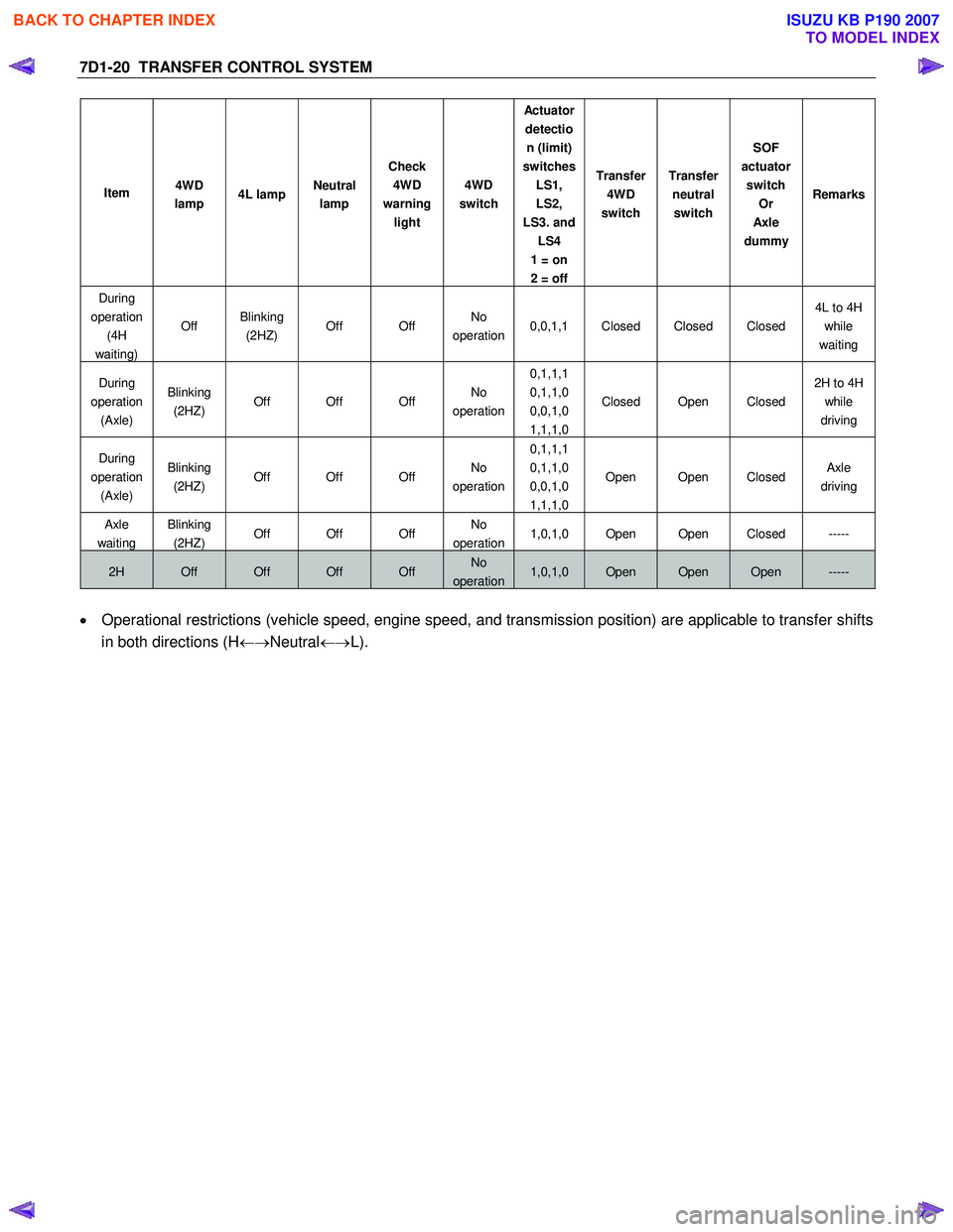
Item 4WD
lamp 4L lamp Neutral
lamp Check
4WD
warning light 4WD
switch Actu ato r
detection (limit)
switches LS1,
LS2,
LS3. and LS4
1 = on
2 = off Transfer
4WD
switch Transfer
neutral switch SOF
actuator switch Or
Axl e
dummy Remarks
During
operation (4H
waiting) Off
Blinking
(2HZ) Off Off No
operation 0,0,1,1 Closed Closed Closed 4L to 4H
while
waiting
During
operation (Axle) Blinking
(2HZ) Off Off Off No
operation 0,1,1,1
0,1,1,0
0,0,1,0
1,1,1,0 Closed Open Closed
2H to 4H
while
driving
During
operation (Axle) Blinking
(2HZ) Off Off Off No
operation 0,1,1,1
0,1,1,0
0,0,1,0
1,1,1,0 Open Open Closed
Axle
driving
Axle
waiting
Blinking
(2HZ) Off Off Off No
operation1,0,1,0 Open Open Closed -----
2H Off Off Off Off No
operation1,0,1,0 Open Open Open -----
• Operational restrictions (vehicle speed, engine speed, and transmission position) are applicable to transfer shifts
in both directions (H ←→Neutral ←→L).
BACK TO CHAPTER INDEX
TO MODEL INDEX
ISUZU KB P190 2007
Page 4917 of 6020
TRANSFER CONTROL SYSTEM 7D1-43
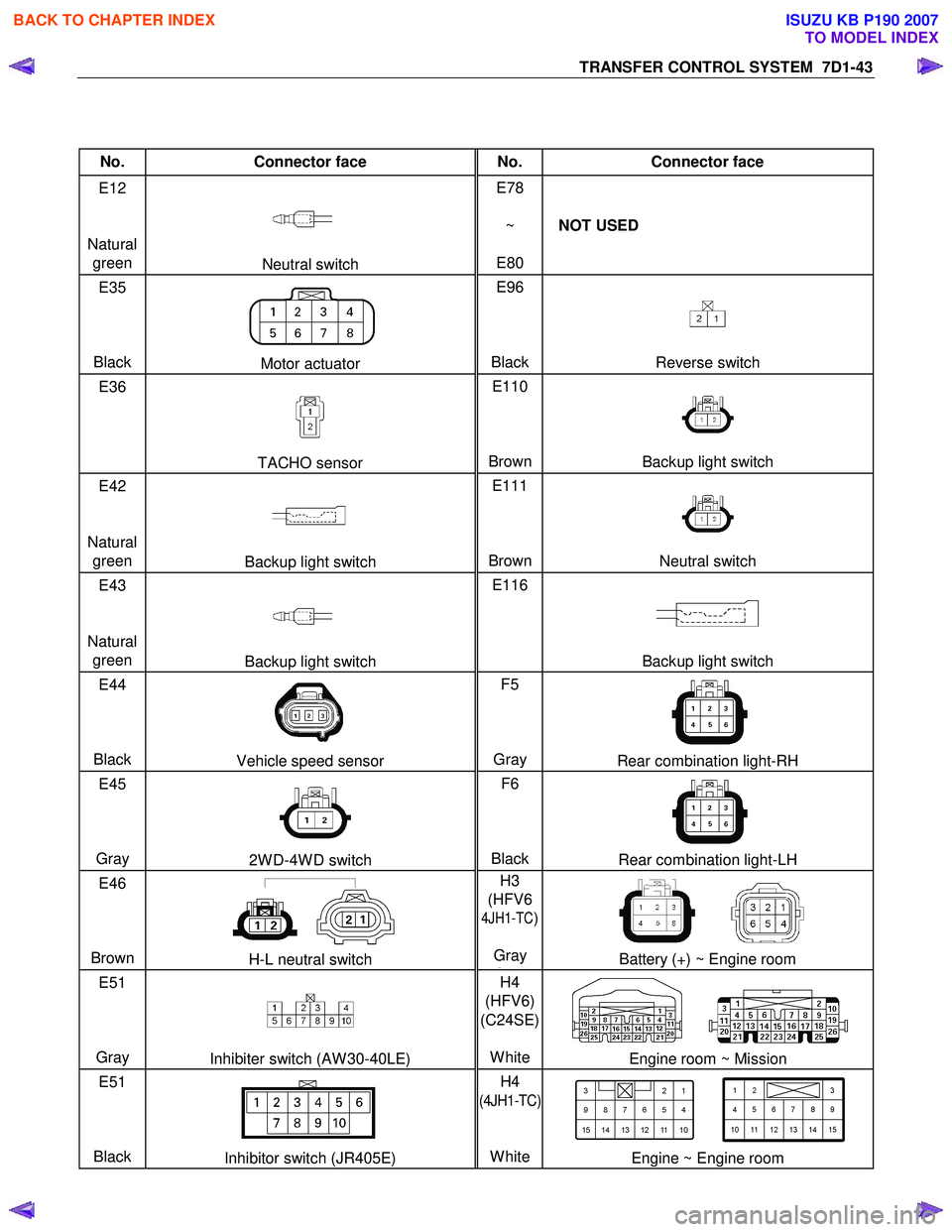
No. Connector face No. Connector face
E12
Natural green
Neutral switch E78
~
E80 NOT USED
E35
Black
Motor actuator E96
BlackReverse switch
E36
TACHO sensor E110
BrownBackup light switch
E42
Natural green
Backup light switch E111
BrownNeutral switch
E43
Natural green
Backup light switch E116
Backup light switch
E44
Black
Vehicle speed sensor F5
Gray Rear combination light-RH
E45
Gray
2W D-4W D switch F6
BlackRear combination light-LH
E46
Brown
H-L neutral switch H3
(HFV6
4JH1-TC)
Gray
GBattery (+) ~ Engine room
E51
Gray
Inhibiter switch (AW 30-40LE) H4
(HFV6)
(C24SE)
WhiteEngine room ~ Mission
E51
Black
Inhibitor switch (JR405E) H4
(4JH1-TC)
White
Engine ~ Engine room
BACK TO CHAPTER INDEX
TO MODEL INDEX
ISUZU KB P190 2007
Page 4925 of 6020
TRANSFER CONTROL SYSTEM 7D1-51
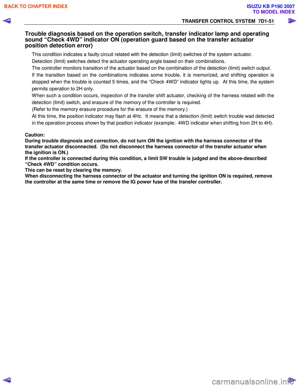
Trouble diagnosis based on the operation switch, transfer indicator lamp and operating
sound “Check 4WD” indicator ON (operation guard based on the transfer actuator
position detection error)
This condition indicates a faulty circuit related with the detection (limit) switches of the system actuator.
Detection (limit) switches detect the actuator operating angle based on their combinations.
The controller monitors transition of the actuator based on the combination of the detection (limit) switch output.
If the transition based on the combinations indicates some trouble, it is memorized, and shifting operation is
stopped when the trouble is counted 5 times, and the “Check 4W D” indicator lights up. At this time, the system
permits operation to 2H only.
W hen such a condition occurs, inspection of the transfer shift actuator, checking of the harness related with the
detection (limit) switch, and erasure of the memory of the controller is required.
(Refer to the memory erasure procedure for the erasure of the memory.)
At this time, the position indicator may flash at 4Hz. It means that a detection (limit) switch trouble wad detected
in the operation process shown by that position indicator (example: 4W D indicator when shifting from 2H to 4H).
Caution:
During trouble diagnosis and correction, do not turn ON the ignition with the harness connector of the
transfer actuator disconnected. (Do not disconnect the harness connector of the transfer actuator when
the ignition is ON.)
If the controller is connected during this condition, a limit SW trouble is judged and the above-described
“Check 4WD” condition occurs.
This can be reset by clearing the memory.
When disconnecting the harness connector of the actuator and turning the ignition ON is required, remove
the controller at the same time or remove the IG power fuse of the transfer controller.
BACK TO CHAPTER INDEX
TO MODEL INDEX
ISUZU KB P190 2007
Page 4928 of 6020
7D1-54 TRANSFER CONTROL SYSTEM
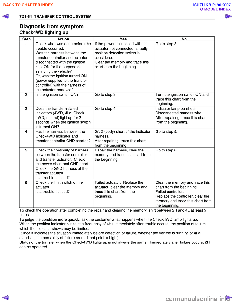
Diagnosis from symptom
Check4WD lighting up
Step Action Yes No
1 Check what was done before the
trouble occurred.
W as the harness between the
transfer controller and actuator
disconnected with the ignition
kept ON for the purpose of
servicing the vehicle?
Or, was the ignition turned ON
(power supplied to the transfer
controller) with the harness of
the actuator removed? If the power is supplied with the
actuator not connected, a faulty
position detection switch is
considered.
Clear the memory and trace this
chart from the beginning. Go to step 2.
2
Is the ignition switch ON? Go to step 3.
Turn the ignition switch ON and
trace this chart from the
beginning.
3 Does the transfer-related
indicators (4W D, 4Lo, Check
4W D, neutral) light up for 2
seconds when the ignition switch
is turned ON? Go to step 4.
Indicator lamp burnt out.
Disconnected harness wire.
After repairing, trace this chart
from the beginning.
4 Has the harness between the
Check4W D indicator and
transfer controller GND shorted? GND (body) short of the indicator
harness.
After repairing, trace this chart
from the beginning. Go to step 5.
5
Check the continuity of harness
between the transfer controller
and transfer actuator. Check
the power short and GND short.
Check the GND harness of the
transfer actuator.
Is a trouble noticed? Repair the harness, clear the
memory and trace this chart from
the beginning. Go to step 6.
6
Check the limit switch of the
actuator.
Is a trouble noticed? Failed actuator. Replace the
actuator, clear the memory and
trace this chart from the
beginning. Clear the memory and trace this
chart from the beginning.
Failed controller.
Replace the controller, clear the
memory and trace this chart from
the beginning.
To check the operation after completing the repair and clearing the memory, shift between 2H and 4L at least 5
times.
To judge the condition more quickly, ask the customer what happens when the Check4W D lamp lights up.
W hen the position indicator blinks at a frequency of 4Hz immediately after trouble occurs, the position of failure
which the indicator shows may be limited.
(Since it indicates the situation immediately before detection of failure, whether the vehicle is running or at a
standstill, the possibility of failure around that point is high.)
Status of the transfer when the Check4W D lights up is not always the same. Immediately after failure occurs, 2H
can be operated.
BACK TO CHAPTER INDEX
TO MODEL INDEX
ISUZU KB P190 2007
Page 4929 of 6020
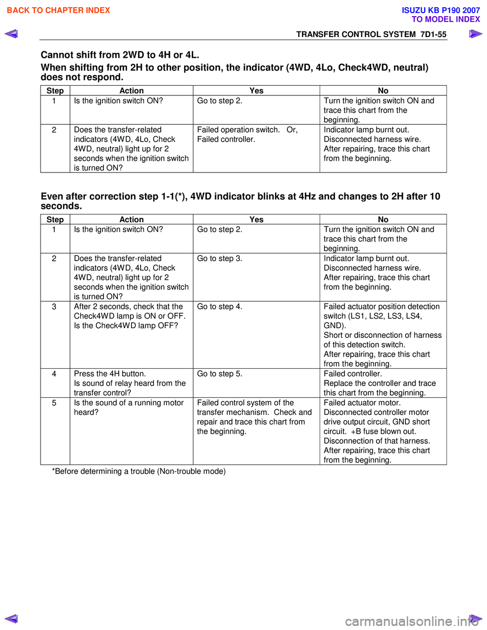
TRANSFER CONTROL SYSTEM 7D1-55
Cannot shift from 2WD to 4H or 4L.
When shifting from 2H to other position, the indicator (4WD, 4Lo, Check4WD, neutral)
does not respond.
Step Action Yes No
1 Is the ignition switch ON? Go to step 2.
Turn the ignition switch ON and
trace this chart from the
beginning.
2 Does the transfer-related
indicators (4W D, 4Lo, Check
4W D, neutral) light up for 2
seconds when the ignition switch
is turned ON? Failed operation switch. Or,
Failed controller. Indicator lamp burnt out.
Disconnected harness wire.
After repairing, trace this chart
from the beginning.
Even after correction step 1-1(*), 4WD indicator blinks at 4Hz and changes to 2H after 10
seconds.
Step Action Yes No
1 Is the ignition switch ON? Go to step 2.
Turn the ignition switch ON and
trace this chart from the
beginning.
2 Does the transfer-related
indicators (4W D, 4Lo, Check
4W D, neutral) light up for 2
seconds when the ignition switch
is turned ON? Go to step 3.
Indicator lamp burnt out.
Disconnected harness wire.
After repairing, trace this chart
from the beginning.
3 After 2 seconds, check that the
Check4W D lamp is ON or OFF.
Is the Check4W D lamp OFF? Go to step 4.
Failed actuator position detection
switch (LS1, LS2, LS3, LS4,
GND).
Short or disconnection of harness
of this detection switch.
After repairing, trace this chart
from the beginning.
4 Press the 4H button.
Is sound of relay heard from the
transfer control? Go to step 5.
Failed controller.
Replace the controller and trace
this chart from the beginning.
5 Is the sound of a running motor
heard? Failed control system of the
transfer mechanism. Check and
repair and trace this chart from
the beginning. Failed actuator motor.
Disconnected controller motor
drive output circuit, GND short
circuit. +B fuse blown out.
Disconnection of that harness.
After repairing, trace this chart
from the beginning.
*Before determining a trouble (Non-trouble mode)
BACK TO CHAPTER INDEX
TO MODEL INDEX
ISUZU KB P190 2007
Page 4932 of 6020
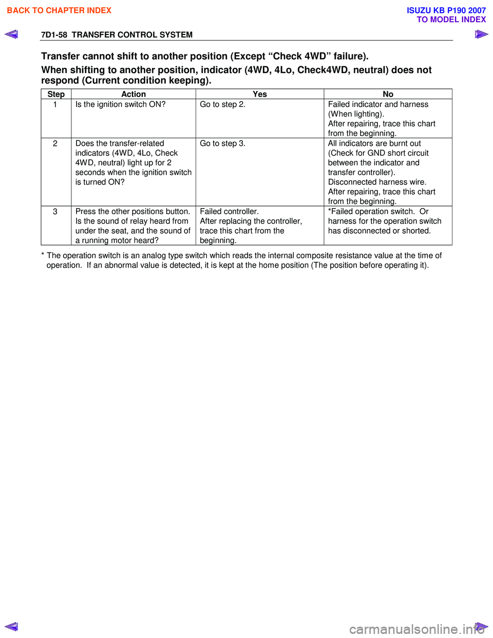
7D1-58 TRANSFER CONTROL SYSTEM
Transfer cannot shift to another position (Except “Check 4WD” failure).
When shifting to another position, indicator (4WD, 4Lo, Check4WD, neutral) does not
respond (Current condition keeping).
Step Action Yes No
1 Is the ignition switch ON? Go to step 2.
Failed indicator and harness
(W hen lighting).
After repairing, trace this chart
from the beginning.
2 Does the transfer-related
indicators (4W D, 4Lo, Check
4W D, neutral) light up for 2
seconds when the ignition switch
is turned ON? Go to step 3.
All indicators are burnt out
(Check for GND short circuit
between the indicator and
transfer controller).
Disconnected harness wire.
After repairing, trace this chart
from the beginning.
3 Press the other positions button.
Is the sound of relay heard from
under the seat, and the sound of
a running motor heard? Failed controller.
After replacing the controller,
trace this chart from the
beginning. *Failed operation switch. Or
harness for the operation switch
has disconnected or shorted.
* The operation switch is an analog type switch which reads the internal composite resistance value at the time of operation. If an abnormal value is detected, it is kept at the home position (The position before operating it).
BACK TO CHAPTER INDEX
TO MODEL INDEX
ISUZU KB P190 2007
Page 4934 of 6020
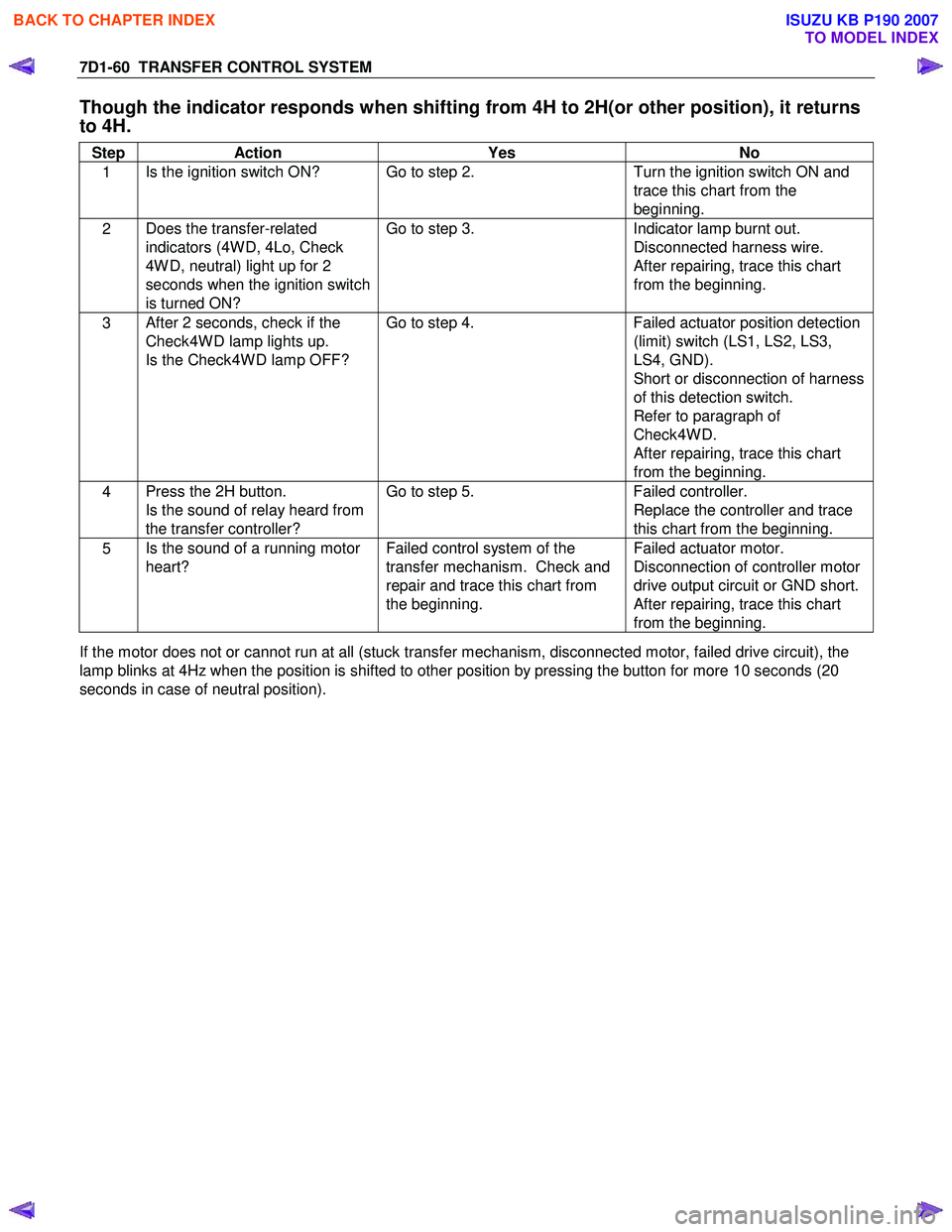
7D1-60 TRANSFER CONTROL SYSTEM
Though the indicator responds when shifting from 4H to 2H(or other position), it returns
to 4H.
Step Action Yes No
1 Is the ignition switch ON? Go to step 2.
Turn the ignition switch ON and
trace this chart from the
beginning.
2 Does the transfer-related
indicators (4W D, 4Lo, Check
4W D, neutral) light up for 2
seconds when the ignition switch
is turned ON? Go to step 3.
Indicator lamp burnt out.
Disconnected harness wire.
After repairing, trace this chart
from the beginning.
3 After 2 seconds, check if the
Check4W D lamp lights up.
Is the Check4W D lamp OFF? Go to step 4.
Failed actuator position detection
(limit) switch (LS1, LS2, LS3,
LS4, GND).
Short or disconnection of harness
of this detection switch.
Refer to paragraph of
Check4W D.
After repairing, trace this chart
from the beginning.
4 Press the 2H button.
Is the sound of relay heard from
the transfer controller? Go to step 5.
Failed controller.
Replace the controller and trace
this chart from the beginning.
5 Is the sound of a running motor
heart? Failed control system of the
transfer mechanism. Check and
repair and trace this chart from
the beginning. Failed actuator motor.
Disconnection of controller motor
drive output circuit or GND short.
After repairing, trace this chart
from the beginning.
If the motor does not or cannot run at all (stuck transfer mechanism, disconnected motor, failed drive circuit), the
lamp blinks at 4Hz when the position is shifted to other position by pressing the button for more 10 seconds (20
seconds in case of neutral position).
BACK TO CHAPTER INDEX
TO MODEL INDEX
ISUZU KB P190 2007
Page 4940 of 6020
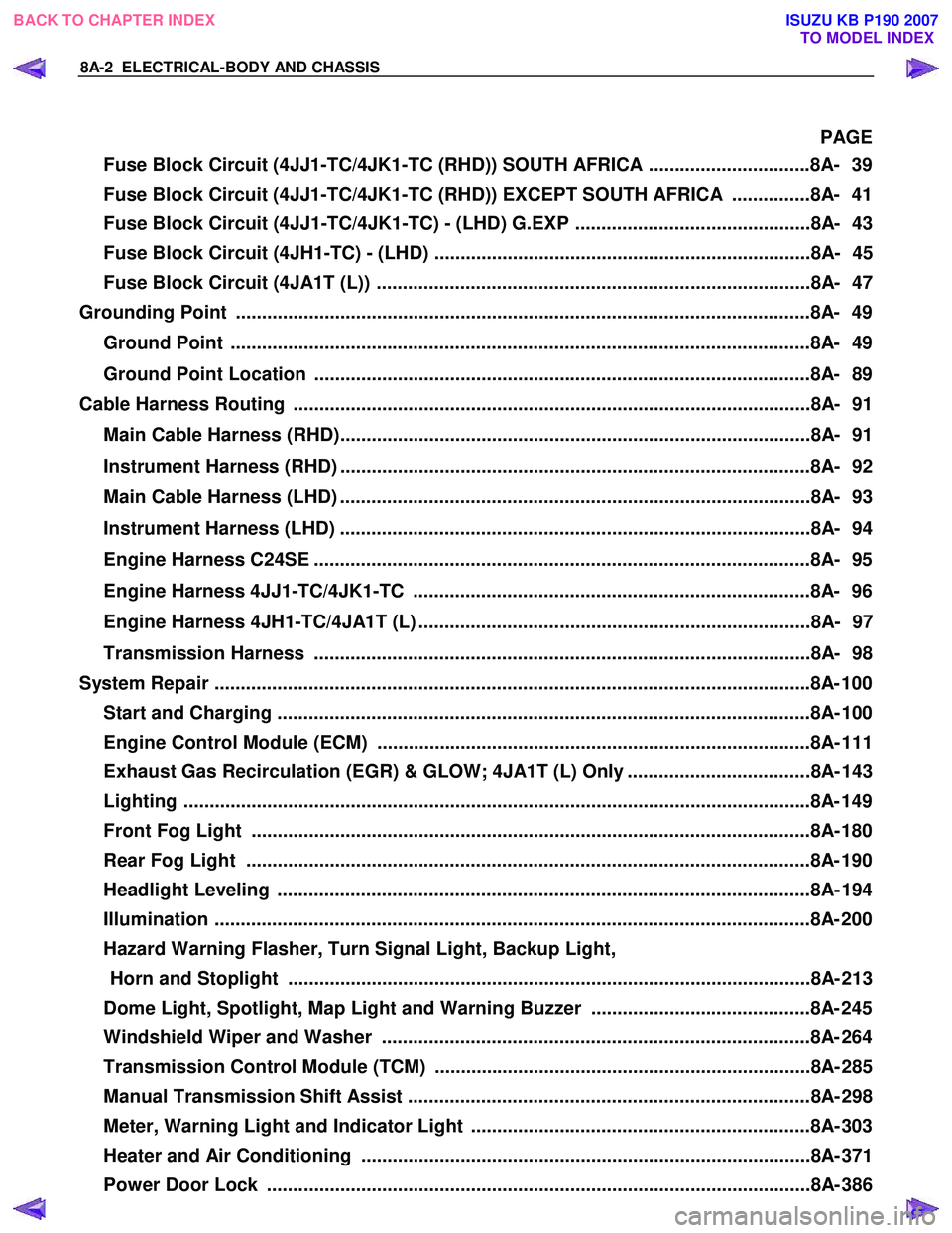
8A-2 ELECTRICAL-BODY AND CHASSIS
PAGE
Fuse Block Circuit (4JJ1-TC/4JK1-TC (RHD)) SOUTH AFRICA ...............................8A- 39
Fuse Block Circuit (4JJ1-TC/4JK1-TC (RHD)) EXCEPT SOUTH AFRICA ...............8A- 41
Fuse Block Circuit (4JJ1-TC/4JK1-TC) - (LHD) G.EXP .............................................8A- 43
Fuse Block Circuit (4JH1-TC) - (LHD) ........................................................................8A- 45
Fuse Block Circuit (4JA1T (L)) ...................................................................................8A- 47
Grounding Point ..............................................................................................................8 A- 49
Ground Point ...............................................................................................................8A- 49
Ground Point Location ...............................................................................................8A- 89
Cable Harness Routing ...................................................................................................8A- 91
Main Cable Harness (RHD)..........................................................................................8A- 91
Instrument Harness (RHD) ..........................................................................................8A- 92
Main Cable Harness (LHD) ..........................................................................................8A- 93
Instrument Harness (LHD) ..........................................................................................8A- 94
Engine Harness C24SE ...............................................................................................8A- 95
Engine Harness 4JJ1-TC/4JK1-TC ............................................................................8A- 96
Engine Harness 4JH1-TC/4JA1T (L) ...........................................................................8A- 97
Transmission Harness ...............................................................................................8A- 98
System Repair ................................................................................................................. .8A- 100
Start and Charging ......................................................................................................8A- 10 0
Engine Control Module (ECM) ...................................................................................8A- 111
Exhaust Gas Recirculation (EGR) & GLOW; 4JA1T (L) Only ...................................8A- 143
Lighting ...................................................................................................................... ..8A- 149
Front Fog Light ...........................................................................................................8A- 180
Rear Fog Light ............................................................................................................8A- 190
Headlight Leveling ......................................................................................................8A- 19 4
Illumination .................................................................................................................. 8A- 200
Hazard Warning Flasher, Turn Signal Light, Backup Light, Horn and Stoplight ....................................................................................................8A- 213
Dome Light, Spotlight, Map Light and Warning Buzzer ..........................................8A- 245
Windshield Wiper and Washer ..................................................................................8A- 264
Transmission Control Module (TCM) ........................................................................8A- 285
Manual Transmission Shift Assist .............................................................................8A- 298
Meter, Warning Light and Indicator Light .................................................................8A- 303
Heater and Air Conditioning ......................................................................................8A- 371
Power Door Lock ........................................................................................................8A- 386
BACK TO CHAPTER INDEX
TO MODEL INDEX
ISUZU KB P190 2007