2007 ISUZU KB P190 steering
[x] Cancel search: steeringPage 3605 of 6020
Charging System – V6 Page 6D1-1-18
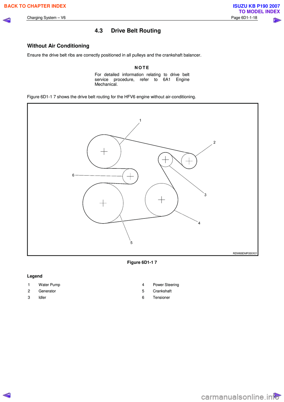
4.3 Drive Belt Routing
Without Air Conditioning
Ensure the drive belt ribs are correctly positioned in all pulleys and the crankshaft balancer.
NOTE
For detailed information relating to drive belt
service procedure, refer to 6A1 Engine
Mechanical.
Figure 6D1-1 7 shows the drive belt routing for the HFV6 engine without air-conditioning.
Figure 6D1-1 7
Legend
1 Water Pump
2 Generator
3 Idler 4 Power Steering
5 Crankshaft
6 Tensioner
BACK TO CHAPTER INDEX
TO MODEL INDEX
ISUZU KB P190 2007
Page 3620 of 6020
Starting System – V6 Page 6D1-2–12
Step Action Yes No
10
1 Connect Tech 2 to the DLC.
2 Ignition on, engine off.
3 On Tech 2 select: Engine / V6 Engine / Data Display / Data List /
Electrical/Theft Data.
4 On Tech 2 scroll to Crank Request.
5 W hile monitoring Tech 2, turn the ignition switch to START.
Does Tech 2 display the following:
Inactive with the ignition switch in the ON position, Active with the
ignition switch in the START position? Go to Step 15 Go to Step 11
11 1 Disconnect the ECM connector C – 56.
2 Using a multimeter set to measure voltage, back probe between the harness connector C56 – X2 pin 31 and ground.
3 W ith the aid of an assistant, monitor the voltage on the multimeter and turn the ignition switch to START.
• W ith the ignition switch in the START position, the
multimeter should display battery voltage
• W ith the ignition switch in the ON position, the multimeter
should display 0 V
Does the multimeter display as described? Refer to 6C1 - 3
Engine
Management – V6 – Service Operations
for further diagnosis.
Go to Step 21 Go to Step 12
12 Test the ignition switch, refer to 3B Steering.
Is the ignition switch serviceable?
Go to Step 13 Replace the faulty
ignition switch. Refer to 3B
Steering
Go to Step 21
13 Check for short to ground or open circuit from the ignition switch start
terminal to the ECM connector C – 56 pin 31.
W as the circuit serviceable? Go to Step 14 Repair as required
(refer to Note 2).
Go to Step 21
14 Check for short to ground or open circuit from the ignition switch
terminal B1 to the fuse SBF5.
W as the circuit serviceable? Go to Step 2 Repair as required
(refer to Note 2).
Go to Step 21
15 NOTE
This procedure is only required on vehicles fitted with
manual transmissions. If the vehicle is fitted with an
automatic transmission, go to Step 16
1 Scroll to Starter Relay
2 W hile monitoring Tech 2, turn the ignition switch to START.
Does Tech 2 display the following:
Off with the ignition switch in the ON position,
On with the ignition switch in the START position?
Go to Step 21 Go to Step 16
BACK TO CHAPTER INDEX
TO MODEL INDEX
ISUZU KB P190 2007
Page 3674 of 6020
Powertrain Interface Module – V6 Page 6E1–13
3.2 Powertrain Interface Module Gateway
Components
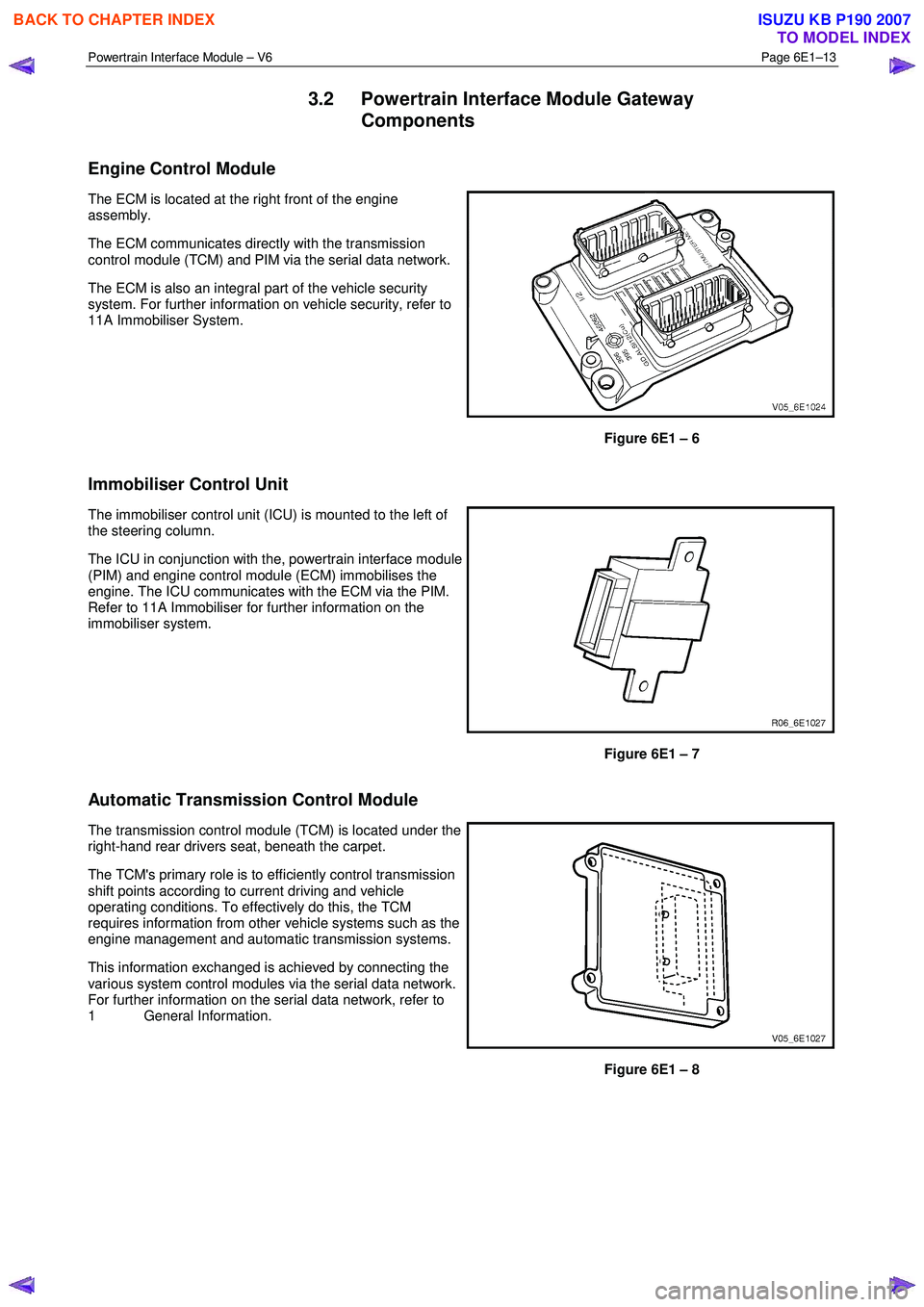
Engine Control Module
The ECM is located at the right front of the engine
assembly.
The ECM communicates directly with the transmission
control module (TCM) and PIM via the serial data network.
The ECM is also an integral part of the vehicle security
system. For further information on vehicle security, refer to
11A Immobiliser System.
Figure 6E1 – 6
Immobiliser Control Unit
The immobiliser control unit (ICU) is mounted to the left of
the steering column.
The ICU in conjunction with the, powertrain interface module
(PIM) and engine control module (ECM) immobilises the
engine. The ICU communicates with the ECM via the PIM.
Refer to 11A Immobiliser for further information on the
immobiliser system.
Figure 6E1 – 7
Automatic Transmission Control Module
The transmission control module (TCM) is located under the
right-hand rear drivers seat, beneath the carpet.
The TCM's primary role is to efficiently control transmission
shift points according to current driving and vehicle
operating conditions. To effectively do this, the TCM
requires information from other vehicle systems such as the
engine management and automatic transmission systems.
This information exchanged is achieved by connecting the
various system control modules via the serial data network.
For further information on the serial data network, refer to
1 General Information.
Figure 6E1 – 8
BACK TO CHAPTER INDEX
TO MODEL INDEX
ISUZU KB P190 2007
Page 3675 of 6020
Powertrain Interface Module – V6 Page 6E1–14
3.3 Powertrain Interface Module Direct Input
Switches
The following switches are direct wired to the PIM. These switches use the PIM to convert their input signals into serial
data, which is then used by the various vehicle control modules to perform varying functions.
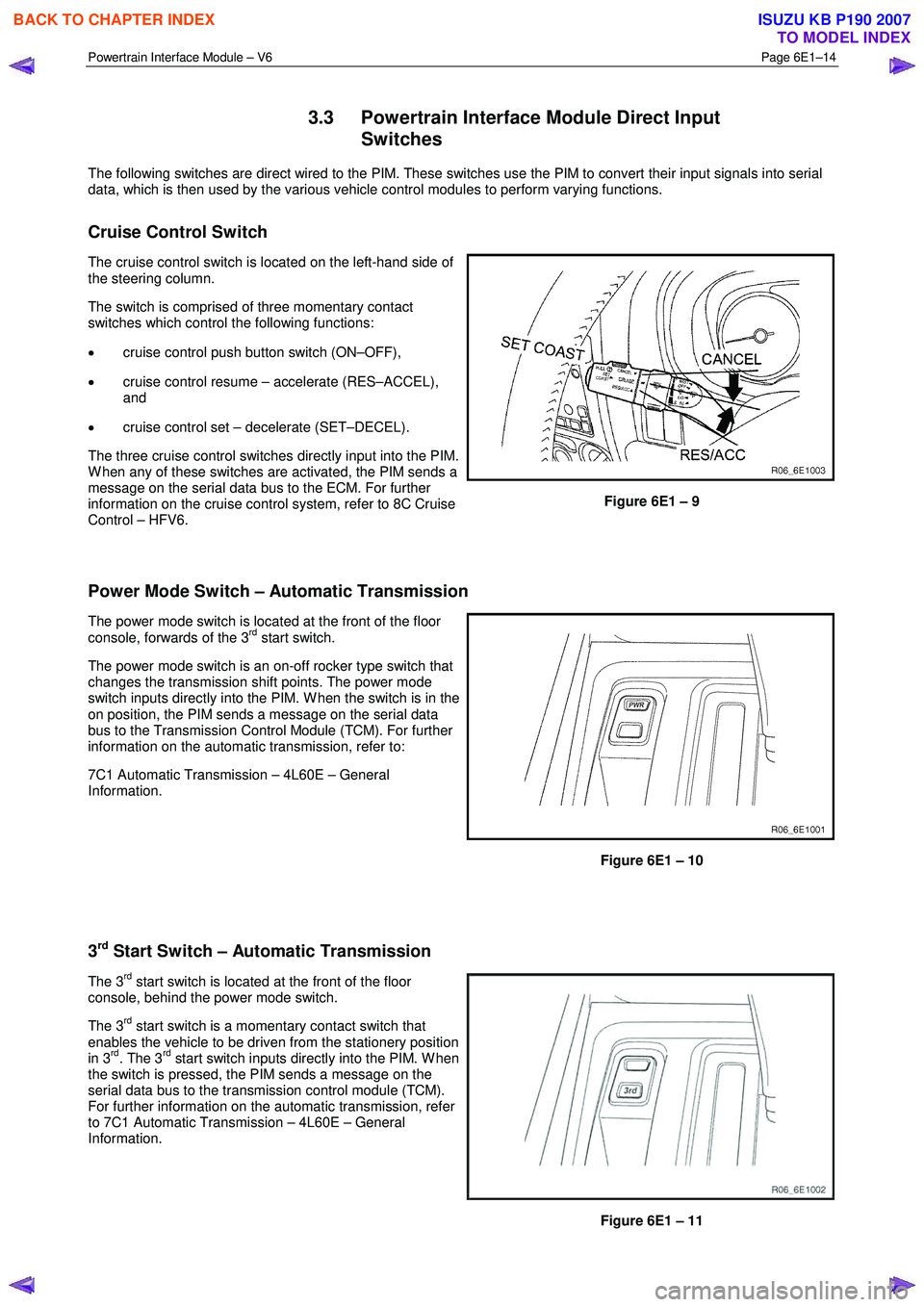
Cruise Control Switch
The cruise control switch is located on the left-hand side of
the steering column.
The switch is comprised of three momentary contact
switches which control the following functions:
• cruise control push button switch (ON–OFF),
• cruise control resume – accelerate (RES–ACCEL),
and
• cruise control set – decelerate (SET–DECEL).
The three cruise control switches directly input into the PIM.
W hen any of these switches are activated, the PIM sends a
message on the serial data bus to the ECM. For further
information on the cruise control system, refer to 8C Cruise
Control – HFV6.
Figure 6E1 – 9
Power Mode Switch – Automatic Transmission
The power mode switch is located at the front of the floor
console, forwards of the 3rd start switch.
The power mode switch is an on-off rocker type switch that
changes the transmission shift points. The power mode
switch inputs directly into the PIM. W hen the switch is in the
on position, the PIM sends a message on the serial data
bus to the Transmission Control Module (TCM). For further
information on the automatic transmission, refer to:
7C1 Automatic Transmission – 4L60E – General
Information.
Figure 6E1 – 10
3
rd Start Switch – Automatic Transmission
The 3rd start switch is located at the front of the floor
console, behind the power mode switch.
The 3
rd start switch is a momentary contact switch that
enables the vehicle to be driven from the stationery position
in 3
rd. The 3rd start switch inputs directly into the PIM. W hen
the switch is pressed, the PIM sends a message on the
serial data bus to the transmission control module (TCM).
For further information on the automatic transmission, refer
to 7C1 Automatic Transmission – 4L60E – General
Information.
Figure 6E1 – 11
BACK TO CHAPTER INDEX
TO MODEL INDEX
ISUZU KB P190 2007
Page 3785 of 6020
Automatic Transmission – 4L60E – General Information Page 7C1–25
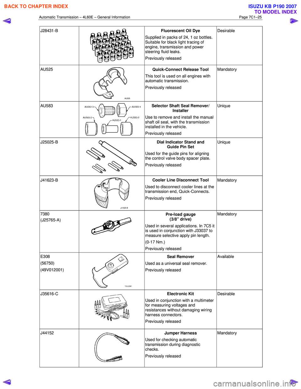
J28431-B
Fluorescent Oil Dye
Supplied in packs of 24, 1 oz bottles.
Suitable for black light tracing of
engine, transmission and power
steering fluid leaks.
Previously released Desirable
AU525
AU525 Quick-Connect Release Tool
This tool is used on all engines with
automatic transmission.
Previously released Mandatory
AU583 Selector Shaft Seal Remover/
Installer
Use to remove and install the manual
shaft oil seal, with the transmission
installed in the vehicle.
Previously released Unique
J25025-B
Dial Indicator Stand and
Guide Pin Set
Used for the guide pins for aligning
the control valve body spacer plate.
Previously released Unique
J41623-B
Cooler Line Disconnect Tool
Used to disconnect cooler lines at the
transmission end, Quick-Connects.
Previously released Mandatory
7380
(J25765-A)
Pre-load gauge
(3/8” drive)
Used in several applications. In 7C5 it
is used in conjunction with J33037 to
measure selective apply pin length.
(0-17 Nm.)
Previously released Mandatory
E308
(56750)
(49V012001)
Seal Remover
Used as a universal seal remover .
Previously released Available
J35616-C
Electronic Kit
Used in conjunction with a multimeter
for measuring voltages and
resistances without damaging wiring
harness connectors.
Previously released Desirable
J44152
Jumper Harness
Used for checking automatic
transmission during diagnostic
checks.
Previously released Mandatory
BACK TO CHAPTER INDEX
TO MODEL INDEX
ISUZU KB P190 2007
Page 3800 of 6020
Automatic Transmission – 4L60E – Electrical Diagnosis Page 7C2–14
3 Tech 2 Information
3.1 Tech 2 Diagnostics
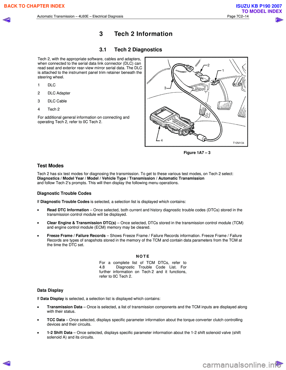
Tech 2, with the appropriate software, cables and adapters,
when connected to the serial data link connector (DLC) can
read seat and exterior rear-view mirror serial data. The DLC
is attached to the instrument panel trim retainer beneath the
steering wheel.
1 DLC
2 DLC Adapter
3 DLC Cable
4 Tech 2
For additional general information on connecting and
operating Tech 2, refer to 0C Tech 2.
Figure 1A7 – 3
Test Modes
Tech 2 has six test modes for diagnosing the transmission. To get to these various test modes, on Tech 2 select:
Diagnostics / Model Year / Model / Vehicle Type / Transmission / Automatic Transmission
and follow Tech 2’s prompts. This will then display the following menu operations.
Diagnostic Trouble Codes
If Diagnostic Trouble Codes is selected, a selection list is displayed which contains:
• Read DTC Information – Once selected, both current and history diagnostic trouble codes (DTCs) stored in the
transmission control module will be displayed.
• Clear Engine & Transmission DTC(s) – Once selected, DTCs stored in the transmission control module (TCM)
and engine control module (ECM) memory may be cleared.
• Freeze Frame / Failure Records – Shows Freeze Frame / Failure Records information. Freeze Frame / Failure
Records are types of snapshots stored in the memory of the TCM and contain data parameters from the TCM at
the time the DTC set.
NOTE
For a complete list of TCM DTCs, refer to
4.8 Diagnostic Trouble Code List. For
further information on Tech 2 and it functions,
refer to 0C Tech 2.
Data Display
If Data Display is selected, a selection list is displayed which contains:
• Transmission Data – Once is selected, a list of transmission components and the TCM inputs are displayed along
with their status.
• TCC Data – Once selected, displays specific parameter information about the torque converter clutch controlling
devices and their circuits.
• 1-2 Shift Data – Once selected, displays specific parameter information about the 1-2 shift solenoid valve (shift
solenoid A) and its circuits.
BACK TO CHAPTER INDEX
TO MODEL INDEX
ISUZU KB P190 2007
Page 5048 of 6020
8A-110 ELECTRICAL-BODY AND CHASSIS
REMOVAL AND INSTALLATION
This illustration is based on RHD model
STARTER SWITCH
Removal
1. Steering Lock Assembly • Refer to Section 3B" STEERING COLUMN" for steering
lock assembly removal steps.
2. Starter Switch
Installation
Follow the removal procedure in the reverse order to install the
starter switch.
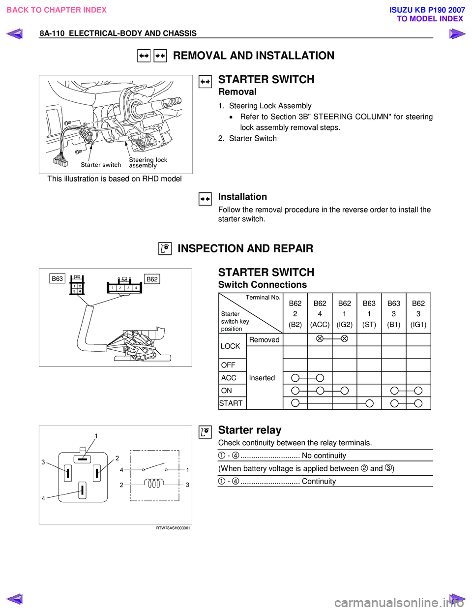
INSPECTION AND REPAIR
B62 B63
STARTER SWITCH
Switch Connections
Terminal No.
Starter
switch key
position B62
2
(B2) B62
4
(ACC) B62
1
(IG2) B63
1
(ST) B63
3
(B1) B62
3
(IG1)
Removed
OFF
ACC Inserted
ON
START
LOCK
RTW 78ASH003001
Starter relay
Check continuity between the relay terminals.
1 - 4............................ No continuity
(W hen battery voltage is applied between 2 and 3)
1 - 4............................ Continuity
BACK TO CHAPTER INDEX TO MODEL INDEXISUZU KB P190 2007
Page 5107 of 6020
ELECTRICAL-BODY AND CHASSIS 8A-169
Installation
Follow the removal procedure in the reverse order to install the
headlight.
Pay close attention to the important points mentioned in the
following paragraphs.
Connector
Be absolutely sure that the headlight connector is securely
connected.
This will prevent a contact and an open circuit.
RTW 780SH000901
This illustration is based on RHD model
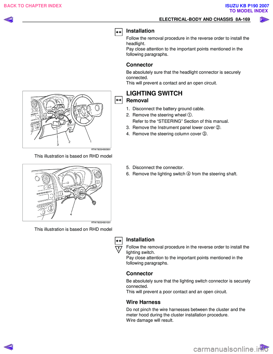
LIGHTING SWITCH
Removal
1. Disconnect the battery ground cable.
2. Remove the steering wheel
1.
Refer to the “STEERING” Section of this manual.
3. Remove the Instrument panel lower cover
2.
4. Remove the steering column cover
3.
RTW 780SH001001
This illustration is based on RHD model
5. Disconnect the connector.
6. Remove the lighting switch
4 from the steering shaft.
Installation
Follow the removal procedure in the reverse order to install the
lighting switch.
Pay close attention to the important points mentioned in the
following paragraphs.
Connector
Be absolutely sure that the lighting switch connector is securely
connected.
This will prevent a poor contact and an open circuit.
Wire Harness
Do not pinch the wire harnesses between the cluster and the
meter hood during the cluster installation procedure.
W ire damage will result.
BACK TO CHAPTER INDEX TO MODEL INDEXISUZU KB P190 2007