2007 ISUZU KB P190 steering
[x] Cancel search: steeringPage 5111 of 6020
ELECTRICAL-BODY AND CHASSIS 8A-173
RTW 780SH000901
RTW 780SH001001
HEADLIGHT BEAM SWITCH
(COMBINATION SWITCH)
Removal
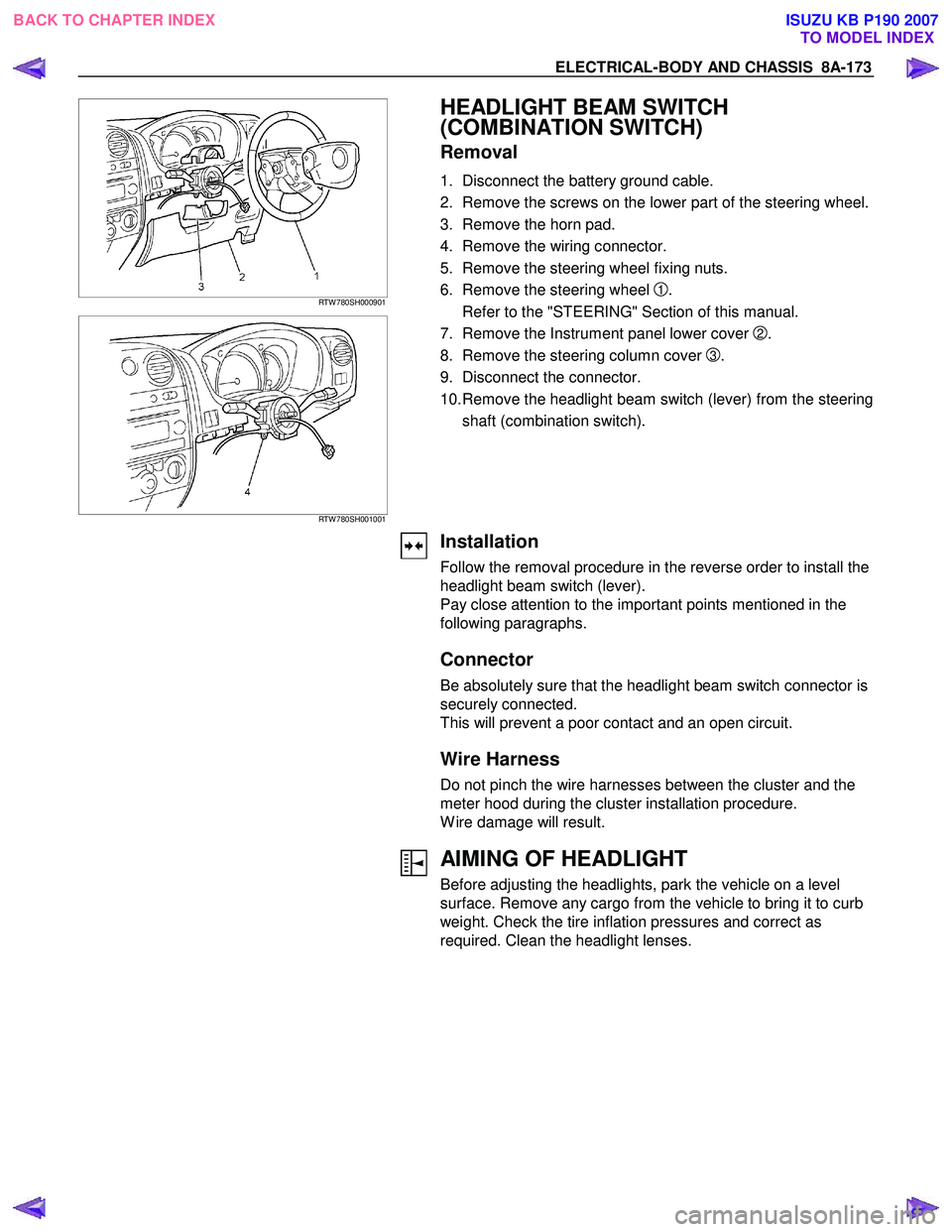
1. Disconnect the battery ground cable.
2. Remove the screws on the lower part of the steering wheel.
3. Remove the horn pad.
4. Remove the wiring connector.
5. Remove the steering wheel fixing nuts.
6. Remove the steering wheel
1.
Refer to the "STEERING" Section of this manual.
7. Remove the Instrument panel lower cover
2.
8. Remove the steering column cover
3.
9. Disconnect the connector.
10. Remove the headlight beam switch (lever) from the steering shaft (combination switch).
Installation
Follow the removal procedure in the reverse order to install the
headlight beam switch (lever).
Pay close attention to the important points mentioned in the
following paragraphs.
Connector
Be absolutely sure that the headlight beam switch connector is
securely connected.
This will prevent a poor contact and an open circuit.
Wire Harness
Do not pinch the wire harnesses between the cluster and the
meter hood during the cluster installation procedure.
W ire damage will result.
AIMING OF HEADLIGHT
Before adjusting the headlights, park the vehicle on a level
surface. Remove any cargo from the vehicle to bring it to curb
weight. Check the tire inflation pressures and correct as
required. Clean the headlight lenses.
BACK TO CHAPTER INDEX TO MODEL INDEXISUZU KB P190 2007
Page 5171 of 6020
ELECTRICAL-BODY AND CHASSIS 8A-233
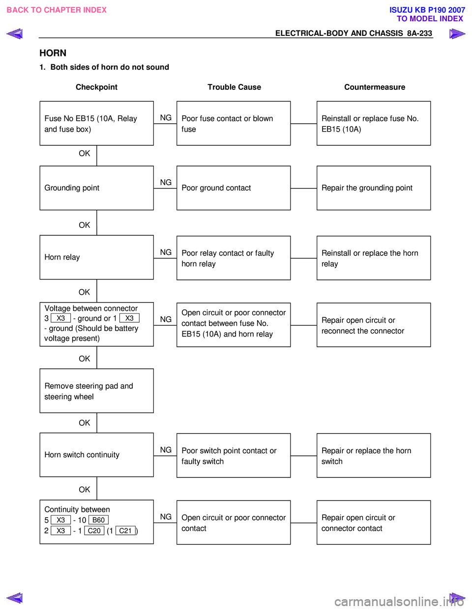
HORN
1. Both sides of horn do not sound
Checkpoint Trouble Cause Countermeasure
Repair the grounding point
Poor ground contact
NG
Horn relay
Grounding point
Reinstall or replace fuse No.
EB15 (10A)
Fuse No EB15 (10A, Relay
and fuse box)
Poor fuse contact or blown
fuse
NG
OK
OK
Reinstall or replace the horn
relay
Poor relay contact or faulty
horn relay
NG
Voltage between connector
3
X3 - ground or 1 X3
- ground (Should be battery
v oltage present) OK
Repair open circuit or
reconnect the connector
Open circuit or poor connector
contact between fuse No.
EB15 (10A) and horn relay
NG
Remov e steering pad and
steering wheel
OK
Horn switch continuity
OK
Repair or replace the horn
switch
Poor switch point contact or
faulty switch
NG
Continuity between
5
X3 - 10 B60
2
X3 - 1 C20 (1 C21 )
OK
Repair open circuit or
connector contact
Open circuit or poor connector
contact
NG
BACK TO CHAPTER INDEX
TO MODEL INDEXISUZU KB P190 2007
Page 5177 of 6020
ELECTRICAL-BODY AND CHASSIS 8A-239
Bulb
Be absolutely sure that the rear combination light bulb is
correctly installed.
This will prevent a poor contact and an open circuit.
RTW 780SH000901
This illustration is based on RHD model
TURN SIGNAL LIGHT SWITCH
Removal
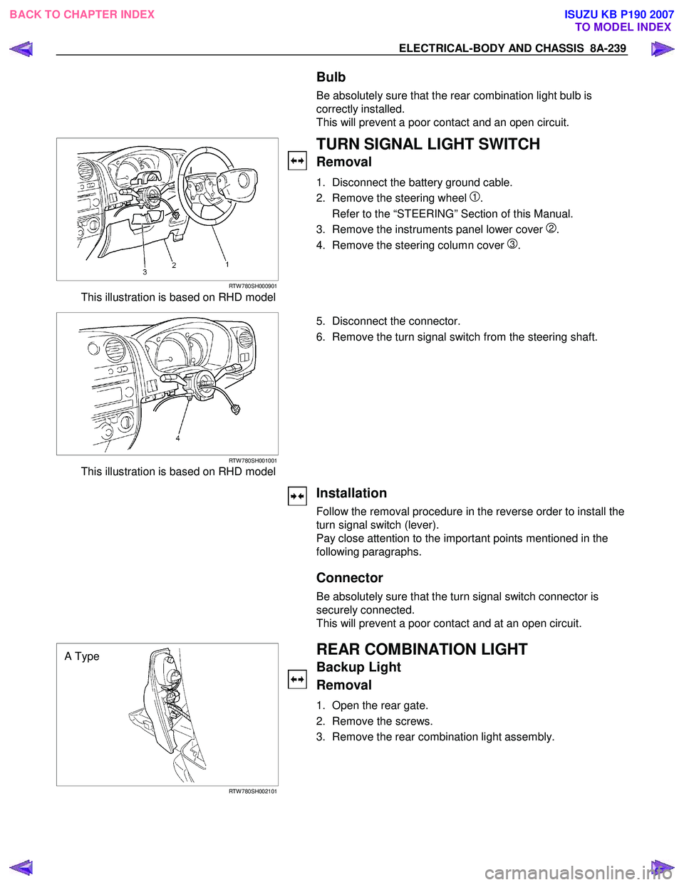
1. Disconnect the battery ground cable.
2. Remove the steering wheel
1.
Refer to the “STEERING” Section of this Manual.
3. Remove the instruments panel lower cover
2.
4. Remove the steering column cover
3.
RTW 780SH001001
This illustration is based on RHD model
5. Disconnect the connector.
6. Remove the turn signal switch from the steering shaft.
Installation
Follow the removal procedure in the reverse order to install the
turn signal switch (lever).
Pay close attention to the important points mentioned in the
following paragraphs.
Connector
Be absolutely sure that the turn signal switch connector is
securely connected.
This will prevent a poor contact and at an open circuit.
A Type
RTW 780SH002101
REAR COMBINATION LIGHT
Backup Light
Removal
1. Open the rear gate.
2. Remove the screws.
3. Remove the rear combination light assembly.
BACK TO CHAPTER INDEX TO MODEL INDEXISUZU KB P190 2007
Page 5180 of 6020
8A-242 ELECTRICAL-BODY AND CHASSIS
HORN SWITCH
Removal
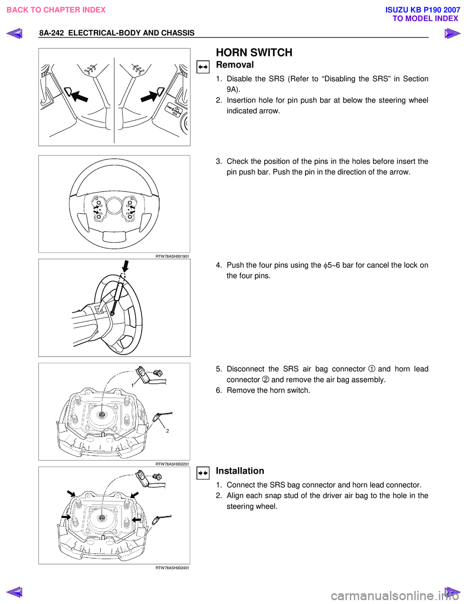
1. Disable the SRS (Refer to “Disabling the SRS” in Section
9A).
2. Insertion hole for pin push bar at below the steering wheel indicated arrow.
RTW 78ASH001901
3. Check the position of the pins in the holes before insert the
pin push bar. Push the pin in the direction of the arrow.
4. Push the four pins using the φ5 ∼6 bar for cancel the lock on
the four pins.
RTW 78ASH002201
5. Disconnect the SRS air bag connector 1 and horn lead
connector
2 and remove the air bag assembly.
6. Remove the horn switch.
RTW 78ASH002401
Installation
1. Connect the SRS bag connector and horn lead connector.
2. Align each snap stud of the driver air bag to the hole in the steering wheel.
BACK TO CHAPTER INDEX TO MODEL INDEXISUZU KB P190 2007
Page 5599 of 6020
Cruise Control – HFV6 Page 8C–21
3.2 Cruise Control Switch Assembly
Remove
To remove the cruise control switch assembly, refer to 8 B Cruise Control System.
Test
To test the cruise control switch assembly, use a multimeter to check the continuity.
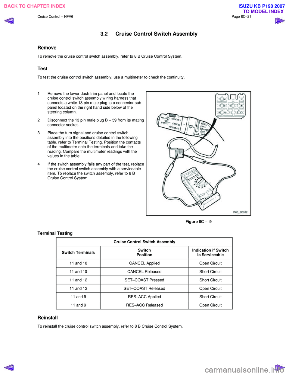
1 Remove the lower dash trim panel and locate the cruise control switch assembly wiring harness that
connects a white 13 pin male plug to a connector sub
panel located on the right hand side below of the
steering column.
2 Disconnect the 13 pin male plug B – 59 from its mating connector socket.
3 Place the turn signal and cruise control switch assembly into the positions detailed in the following
table, refer to Terminal Testing. Position the contacts
of the multimeter onto the terminals and take the
reading. Compare the multimeter readings with the
values in the table.
4 If the switch assembly fails any part of the test, replace the cruise control switch assembly with a serviceable
item. To replace the switch assembly, refer to 8 B
Cruise Control System.
Figure 8C – 9
Terminal Testing
Cruise Control Switch Assembly
Switch Terminals Switch
Position Indication if Switch
is Serviceable
11 and 10 CANCEL Applied Open Circuit
11 and 10 CANCEL Released Short Circuit
11 and 12 SET–COAST Pressed Short Circuit
11 and 12 SET–COAST Released Open Circuit
11 and 9 RES–ACC Applied Short Circuit
11 and 9 RES–ACC Released Open Circuit
Reinstall
To reinstall the cruise control switch assembly, refer to 8 B Cruise Control System.
BACK TO CHAPTER INDEX
TO MODEL INDEXISUZU KB P190 2007
Page 5636 of 6020
SUPPLEMENTAL RESTRAINT SYSTEM 9A-1
SECTION 9A
SUPPLEMENTAL RESTRAINT SYSTEM (SRS)
TABLE OF CONTENTS
PAGE
Service Precaution ....................................................................................................... 9A- 4
General Description...................................................................................................... 9A- 4 Restraint Devices ..................................................................................................... 9A- 4
System Description .................................................................................................. 9A- 5
Circuit Diagram ............................................................................................................. 9A- 6
SRS Component And Wiring Location View .............................................................. 9A- 10
Component Description ............................................................................................... 9A- 14 SRS Control Unit ...................................................................................................... 9A- 14
"SRS" Warning Lamp .............................................................................................. 9A- 14
SRS Coil Assembly .................................................................................................. 9A- 15
Air Bag Assemblies.................................................................................................. 9A- 15
Steering Column ...................................................................................................... 9A- 16
Knee Bolster ............................................................................................................. 9A- 16
Definitions .................................................................................................................... . 9A- 16
Diagnosis...................................................................................................................... . 9A- 18
Diagnostic Trouble Codes ....................................................................................... 9A- 18
Scan Tool Diagnostics............................................................................................. 9A- 18
Use Of Special Tools ............................................................................................... 9A- 18
SRS Connec tor Body Face Vie ws ............................................................................. ..9 A- 19
Repairs And Inspec tions Required After A n A ccident ............................................ ..9 A- 20
Accident With Deployment-Component Replacement And Inspections ............. 9A- 20
Accident With or Without Deployment-Component Inspection ........................... 9A- 20
SRS Control Unit Replacement Guidelines ........................................................... 9A- 20
Wiring Damage ......................................................................................................... 9A- 20
SRS Connector (Plastic Body And Terminal Metal Pin) Damage ......................... 9A- 20
SRS Wire Pigtail Damage ........................................................................................ 9A- 20
PAGE 1 OF 3
BACK TO CHAPTER INDEX TO MODEL INDEXISUZU KB P190 2007
Page 5638 of 6020
SUPPLEMENTAL RESTRAINT SYSTEM 9A-3
PAGE
Steering Wheel .............................................................................................................. 9A- 38
Service Precautions ................................................................................................. 9A- 38
Removal .................................................................................................................... 9A- 38
Installation ................................................................................................................ 9A- 38
SRS Coil Assembly ....................................................................................................... 9A- 39 Service Precautions ................................................................................................. 9A- 39
Removal. ................................................................................................................... 9A- 39
Installation. ............................................................................................................... 9A- 39
Steering Column ........................................................................................................... 9A- 4 0
Service Precautions ................................................................................................. 9A- 40
Removal .................................................................................................................... 9A- 40
Installation ................................................................................................................ 9A- 40
Passenger Air Bag Assembly ...................................................................................... 9A- 41 Service Precautions ................................................................................................. 9A- 41
Removal .................................................................................................................... 9A- 41
Installation ................................................................................................................ 9A- 42
Pretensioner Seat Belt (If so equipped) ...................................................................... 9A- 43 Removal .................................................................................................................... 9A- 43
Installation ................................................................................................................ 9A- 43
Main Data and Specifications ...................................................................................... 9A- 44 Fastener Tightening Specification.......................................................................... 9A- 44
Special Tools................................................................................................................. 9 A- 45
PAGE 3 OF 3
BACK TO CHAPTER INDEX TO MODEL INDEXISUZU KB P190 2007
Page 5639 of 6020
9A-4 SUPPLEMENTAL RESTRAINT SYSTEM
Service Precaution
WARNING: THIS VEHICLE HAS A SUPPLEMENTAL
RESTRAINT SYSTEM (SRS). REFER TO THE SRS
COMPONENT AND WIRING LOCATION VIEW IN
ORDER TO DETERMINE WHETHER YOU ARE
PERFORMING A SERVICE ON, OR NEAR, THE SRS
COMPONENTS OR THE SRS WIRING. WHEN YOU
ARE PERFORMING A SERVICE ON OR NEAR THE
SRS COMPONENTS OR THE SRS WIRING, REFER
TO THE SRS SERVICE INFORMATION. FAILURE
TO FOLLOW WARNINGS COULD RESULT IN
POSSIBLE AIR BAG DEPLOYMENT, PERSONAL
INJURY, OR OTHERWISE UNNECESSARY SRS
SYSTEM REPAIRS.
CAUTION: Always use the correct fastener in the
proper location. When you replace a fastener, use
ONLY the exact part number for that application.
ISUZU/GM will call out those fasteners that require
a replacement after removal. ISUZU/GM will also
call out the fasteners that require thread lockers o
r
thread sealant. UNLESS OTHERWISE SPECIFIED,
do not use supplemental coatings (paints,
greases, or other corrosion inhibitors) on threaded
fasteners or fastener joint interfaces. Generally,
such coatings adversely affect the fastener torque
and the joint clamping force, and may damage the
fastener. When you install fasteners, use the
correct tightening sequence and specifications.
Following these instructions can help you avoid
damage to parts and systems.
General Description
CAUTION: When fasteners are removed, always
reinstall them at the same location from which
they were removed. If a fastener needs to be
replaced, use the correct part number fastener fo
r
that application. If the correct part numbe
r
fastener is not available, a fastener of equal size
and strength (or stronger) may be used.
Fasteners that are not reused, and those requiring
thread locking compound will be called out. The
correct torque value must be used when installing
fasteners that require it. If the above conditions
are not followed, parts or system damage could
result.
Restraint Devices
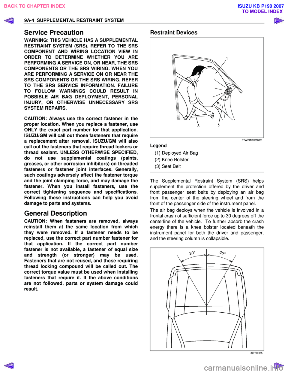
RTW 79ASH000801
Legend
(1) Deployed Air Bag
(2) Knee Bolster
(3) Seat Belt
The Supplemental Restraint System (SRS) helps
supplement the protection offered by the driver and
front passenger seat belts by deploying an air bag
from the center of the steering wheel and from the
front of the passenger side of the instrument panel.
The air bag deploys when the vehicle is involved in a
frontal crash of sufficient force up to 30 degrees off the
centerline of the vehicle. To further absorb the crash
energy there is a knee bolster located beneath the
instrument panel for both the driver and passenger,
and the steering column is collapsible.
827RW 005
BACK TO CHAPTER INDEX TO MODEL INDEXISUZU KB P190 2007