2007 ISUZU KB P190 steering
[x] Cancel search: steeringPage 2881 of 6020
Engine Mechanical – V6 Page 6A1–104
Page 6A1–104
3.15 Front Cover Assembly
Remove
1 Drain the engine coolant, refer to Section 6B1 Engine Cooling.
2 Remove the water outlet pipe and coolant pump assembly, refer to Section 6B1 Engine Cooling:
3 Remove the camsha ft covers, refer to 3.12 Camshaft Cover .
4 Remove the crankshaft bal ancer assembly, refer to 3.13 Crankshaft Balancer Assembly .
5 Disconnect the purge vent hose from the water outlet pipe.
NOTE
Do not disconnect the power steering pipes or
drain the power steering fluid.
6 Remove the power steering pump reservoir mounting bracket, refer to 3.8 Power Steering Pump Bracket.
7 Remove the camshaft position sensor, refer to Section 6C1-3 Engine Management – V6 – Service Operations.
NOTE
Do not disconnect the A/C compressor pipes.
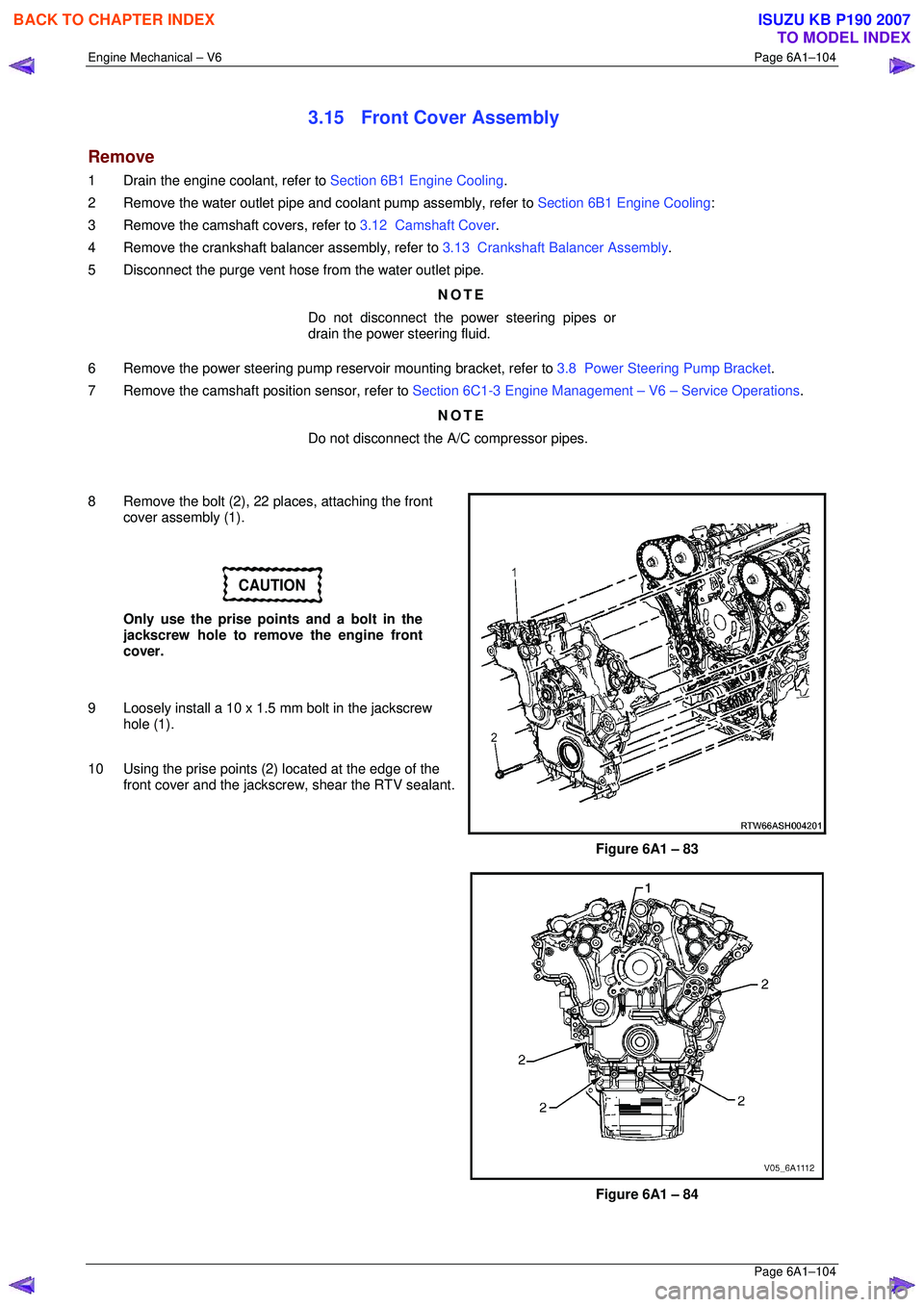
8 Remove the bolt (2), 22 places, attaching the front cover assembly (1).
CAUTION
Only use the prise points and a bolt in the
jackscrew hole to remove the engine front
cover.
9 Loosely install a 10 x 1.5 mm bolt in the jackscrew hole (1).
10 Using the prise points (2) located at the edge of the
front cover and the jackscrew, shear the RTV sealant.
Figure 6A1 – 83
Figure 6A1 – 84
BACK TO CHAPTER INDEX
TO MODEL INDEX
ISUZU KB P190 2007
Page 2995 of 6020
Engine Mechanical – V6 Page 6A1–218
Page 6A1–218
Left-hand Side (Bank 2) Cylinder Head
1 Remove the intake manifold assembly, refer to 3.10 Intake Manifold Assembly – Complete .
2 Remove the exhaust manifold, refer to 3.11 Exhaust Manifold Assembly.
3 Remove the power steering reservoi r and pump mounting brackets, refer to 3.8 Power Steering Pump Bracket.
NOTE
Do not disconnect the power steering pipes
and/or hoses.
4 Remove the oil filter adapter upper bolt. NOTE
Do not remove the oil filter adapter.
5 Remove the engine coolant temper ature (ECT) sensor, refer to Section 6C1-3 Engine Management – V6 – Service
Operations .
6 Remove engine harness ground terminal attach ing bolt from cylinder head, refer to Section 8A Electrical Body &
Chassis .
7 Remove the left-hand bank secondary timing chain, refer to 3.16 Timing Chains, Tensioners, Shoes and Guides.
8 Remove the camshaft position actuators, refer to 3.18 Camshaft Sprocket.
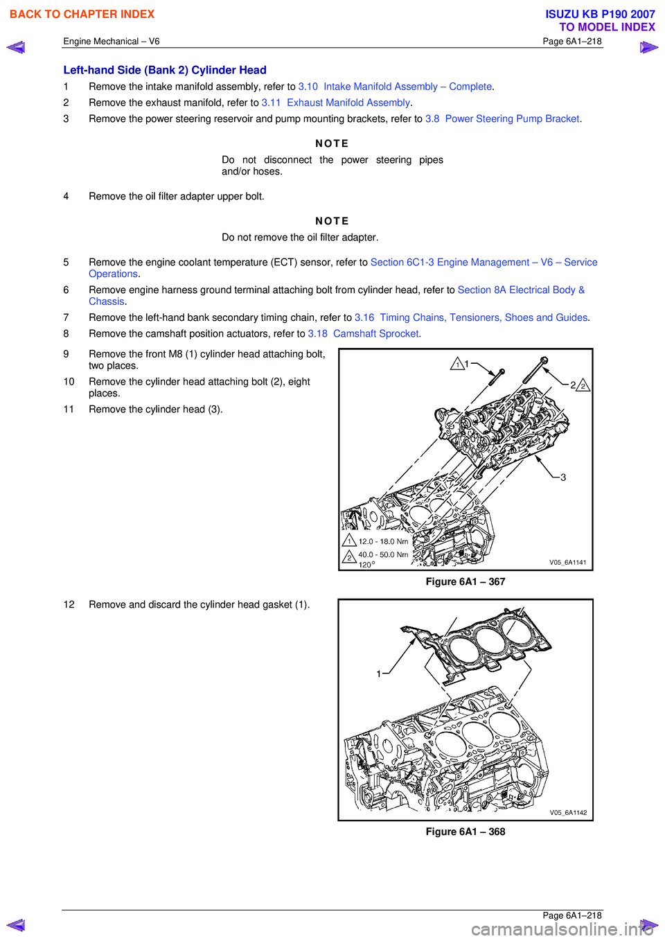
9 Remove the front M8 (1) cylinder head attaching bolt, two places.
10 Remove the cylinder head attaching bolt (2), eight places.
11 Remove the cylinder head (3).
Figure 6A1 – 367
12 Remove and discard the cylinder head gasket (1).
Figure 6A1 – 368
BACK TO CHAPTER INDEX
TO MODEL INDEX
ISUZU KB P190 2007
Page 3025 of 6020
Engine Mechanical – V6 Page 6A1–248
Page 6A1–248
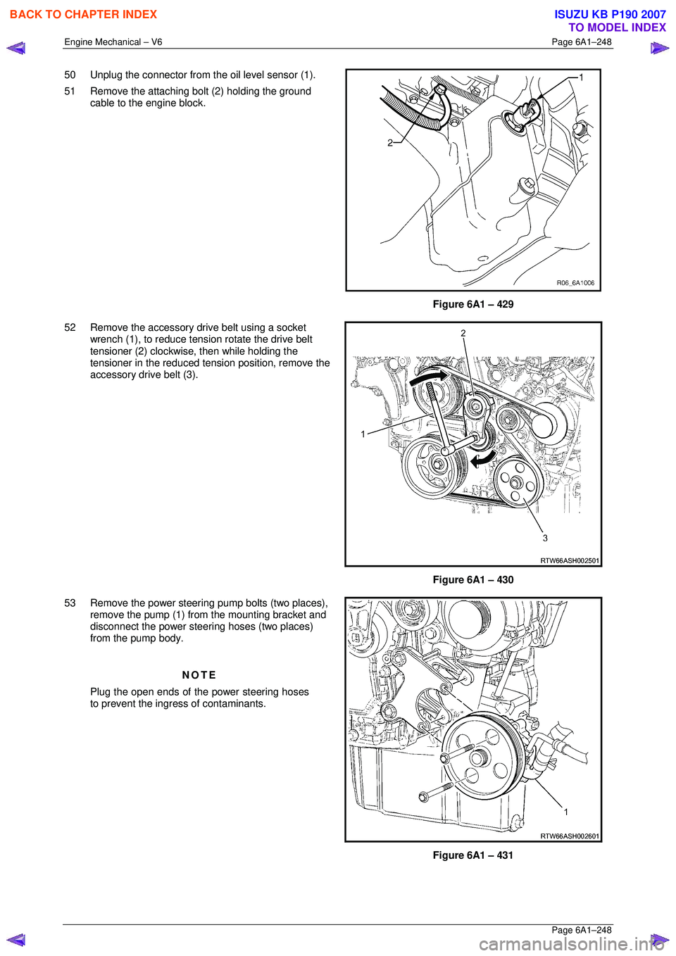
50 Unplug the connector from the oil level sensor (1).
51 Remove the attaching bolt (2) holding the ground cable to the engine block.
Figure 6A1 – 429
52 Remove the accessory drive belt using a socket wrench (1), to reduce tension rotate the drive belt
tensioner (2) clockwise, then while holding the
tensioner in the reduced tens ion position, remove the
accessory drive belt (3).
Figure 6A1 – 430
53 Remove the power steering pump bolts (two places),
remove the pump (1) from the mounting bracket and
disconnect the power steering hoses (two places)
from the pump body.
NOTE
Plug the open ends of the power steering hoses
to prevent the ingre ss of contaminants.
Figure 6A1 – 431
BACK TO CHAPTER INDEX
TO MODEL INDEX
ISUZU KB P190 2007
Page 3026 of 6020
Engine Mechanical – V6 Page 6A1–249
Page 6A1–249
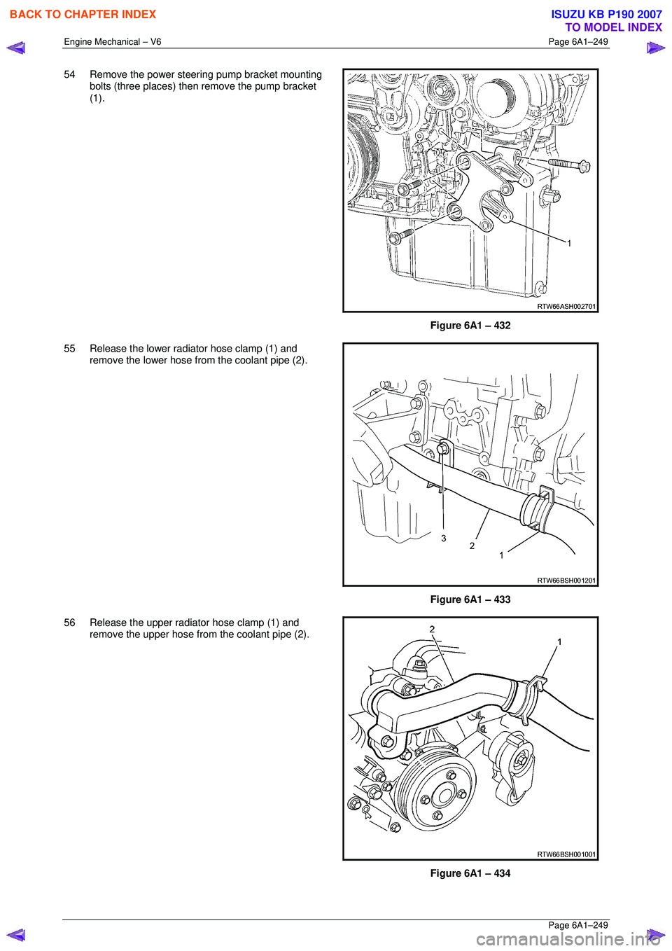
54 Remove the power steering pump bracket mounting
bolts (three places) then remove the pump bracket
(1).
Figure 6A1 – 432
55 Release the lower radiator hose clamp (1) and remove the lower hose from the coolant pipe (2).
Figure 6A1 – 433
56 Release the upper radiator hose clamp (1) and remove the upper hose from the coolant pipe (2).
Figure 6A1 – 434
BACK TO CHAPTER INDEX
TO MODEL INDEX
ISUZU KB P190 2007
Page 3030 of 6020
Engine Mechanical – V6 Page 6A1–253
Page 6A1–253
k Timing chains, tensioners, shoes, guides & sprockets, refer to 3.16 Timing Chains, Tensioners, Shoes and
Guides .
l Cylinder head assemblies, refer to 3.22 Cylinder Head Assembly.
m Oil pan assembly, refer to 4.2 Oil Pan and Oil Pump Suction Pipe Assembly .
n Piston and connecting rod assemblies, refer to 4.5 Pistons, Pins, Rings, Connecting Rods and Big-end
Bearings .
o Crankshaft assembly, refer to 4.6 Crankshaft and Main Bearings.
p Piston oil nozzles, refer 4.5 Pistons, Pins, Rings, Connecting Rods and Big-end Bearings .
Reassemble
Reassembly of the engine assembly is the reverse of the disassembly procedure.
Reinstall
Reinstallation of the engine assembly is the revers e to the removal procedure, noting the following:
NOTE
Refer to 6 Torque Wrench Specifications for the
correct torque specifications.
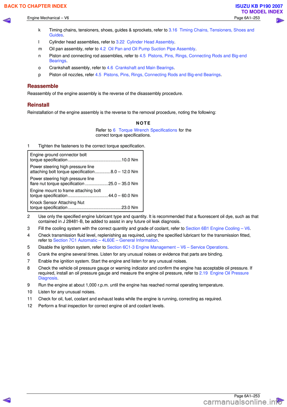
1 Tighten the fasteners to the co rrect torque specification.
Engine ground connector bolt
torque specificat ion ............................................ 10.0 Nm
Power steering high pressure line
attaching bolt torque specification ............. 8.0 – 12.0 Nm
Power steering high pressure line
flare nut torque specif ication ................... 25. 0 – 35.0 Nm
Engine mount to frame attaching bolt
torque specification ................................. 44. 0 – 60.0 Nm
Knock Sensor Attaching Nut
torque specification ............................................ 23.0 Nm
2 Use only the specified engine lubricant type and quantity. It is recommended that a fluorescent oil dye, such as that
contained in J 28481-B, be added to assist in any future oil leak diagnosis.
3 Fill the cooling system with the corre ct quantity and grade of coolant, refer to Section 6B1 Engine Cooling – V6.
4 Check transmission fluid level, replenishing as required, using the specified lubricant for the transmission fitted,
refer to Section 7C1 Automatic – 4L60E – General Information .
5 Disable the ignition system, refer to Section 6C1-3 Engine Management – V6 – Service Operations.
6 Crank the engine several times. Listen for any unusual noises or evidence that parts are binding.
7 Enable the ignition system. Start t he engine and listen for any unusual noises.
8 Check the vehicle oil pressure gauge or warning indica tor and confirm the engine has acceptable oil pressure. If
required, install an oil pressure gauge and m easure the engine oil pressure, refer to 2.19 Engine Oil Pressure
Diagnosis .
9 Run the engine at about 1,000 r. p.m. until the engine has reached normal operating temperature.
10 Listen for any unusual noises.
11 Check for oil, fuel, coolant and exhaust leaks wh ile the engine is running, correcting as required.
12 Perform a final inspection for correct engine oil and coolant levels.
BACK TO CHAPTER INDEX
TO MODEL INDEX
ISUZU KB P190 2007
Page 3128 of 6020
Engine Mechanical – V6 Page 6A1–351
Page 6A1–351
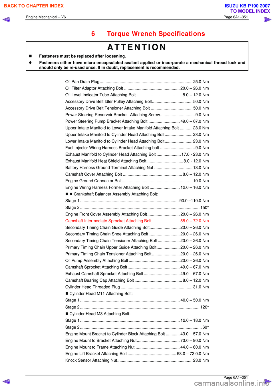
6 Torque Wrench Specifications
ATTENTION
�„ Fasteners must be replaced after loosening.
Fasteners either have micro encapsulated sealant a pplied or incorporate a mechanical thread lock and
should only be re-used once. If in doubt, replacement is recommended.
Oil Pan Drain Plug ................................................................................ 25.0 Nm
Oil Filter Adaptor Attach ing Bolt................................................ 20.0 – 26.0 Nm
Oil Level Indicator Tube Atta ching Bolt........................................ 8.0 – 12.0 Nm
Accessory Drive Belt Idler Pu lley Attaching Bolt................................... 50.0 Nm
Accessory Drive Belt Tensio ner Attaching Bolt .................................... 50.0 Nm
Power Steering Reserv oir Bracket Attaching Screw.............................. 9.0 Nm
Power Steering Pump Bracket A ttaching Bolt ........................... 49. 0 – 67.0 Nm
Upper Intake Manifold to Lower Intake Manifold Attaching Bolt ........... 23.0 Nm
Upper Intake Manifold to Cylinder Head Attaching Bolt........................ 23.0 Nm
Lower Intake Manifold to Cylind er Head Attaching Bolt........................ 23.0 Nm
Fuel Injector Wiring Harness Br acket Attaching bolt .............................. 9. 0 Nm
Exhaust Manifold to Cylinder He ad Attaching Bolt..................... 17.0 - 23.0 Nm
Exhaust Manifold Heat Shield Attaching Bolt ............................... 8.0 - 12.0 Nm
Battery Harness Ground Terminal Attaching Nut ................................. 13. 0 Nm
Camshaft Cover Attachi ng Bolt................................................... 8.0 – 12.0 Nm
Engine Ground Connec tor Bolt............................................................. 10.0 Nm
Engine Wiring Harness Former A ttaching Bolt .......................... 12.0 – 16.0 Nm
�„ Crankshaft Balancer A ssembly Attaching Bolt:
Stage 1 ..................................................................................... 90.0 –110.0 Nm
Stage 2 ....................................................................................................... 150 °
Engine Front Cover Assembly A ttaching Bolt ............................ 20. 0 – 26.0 Nm
Camshaft Intermediate Sprocket Attaching Bolt ........................ 58. 0 – 72.0 Nm
Secondary Timing Chai n Guide Attaching Bolt.......................... 20.0 – 26.0 Nm
Secondary Timing Chai n Shoe Attaching Bolt ........................... 20.0 – 26.0 Nm
Secondary Timing Chain Tensioner Attachi ng Bolt ................... 20.0 – 26.0 Nm
Primary Timing Chain Upper Gui de Attaching Bolt.................... 20.0 – 26.0 Nm
Primary Timing Chain Tensioner Attaching Bolt........................ 20. 0 – 26.0 Nm
Oil Pump Assembly Attach ing Bolt............................................ 20.0 – 26.0 Nm
Camshaft Sprocket Attachi ng Bolt............................................. 49.0 – 67.0 Nm
Exhaust Camshaft Sprocket Atta ching Bolt............................... 49.0 – 67.0 Nm
Camshaft Bearing Cap Attach ing Bolt......................................... 8.0 – 12.0 Nm
Cylinder Head Thr eaded Plug.............................................................. 31.0 Nm
�„ Cylinder Head M11 Attaching Bolt:
Stage 1 ...................................................................................... 40.0 – 50.0 Nm
Stage 2 ....................................................................................................... 120 °
�„ Cylinder Head M8 Attaching Bolt:
Stage 1 ...................................................................................... 12.0 – 18.0 Nm
Stage 2 ......................................................................................................... 60 °
Engine Mount Bracket to Cylinder Bl ock Attaching Bolt............ 43.0 – 57.0 Nm
Engine Mount to Bracket Atta ching Nut..................................... 70.0 – 90.0 Nm
Engine Mount to Frame Atta ching Nut...................................... 44.0 – 60.0 Nm
Engine Lift Bracket Attachi ng Bolt.......................................... 58.0 – 72.0.0 Nm
Knock Sensor Attach ing Nut................................................................. 23.0 Nm
BACK TO CHAPTER INDEX
TO MODEL INDEX
ISUZU KB P190 2007
Page 3129 of 6020
Engine Mechanical – V6 Page 6A1–352
Page 6A1–352
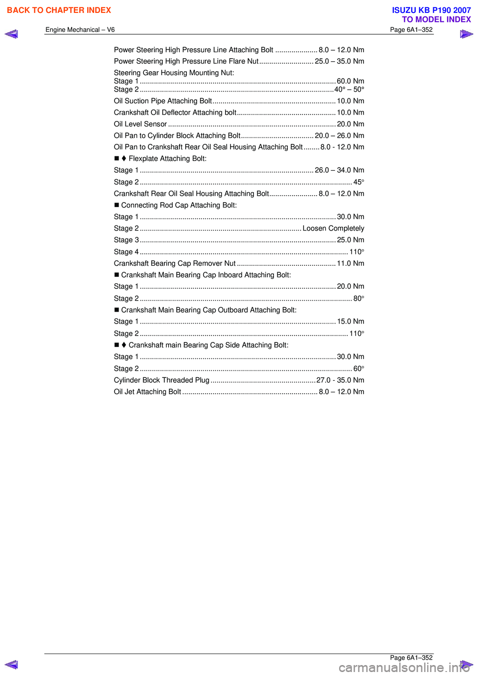
Power Steering High Pressure Line Attaching Bolt..................... 8.0 – 12.0 Nm
Power Steering High Pressure Li ne Flare Nut ...........................25.0 – 35.0 Nm
Steering Gear Housing Mounting Nut:
Stage 1 ................................................................................................. 60.0 Nm
Stage 2 ................................................................................................ 40° – 50°
Oil Suction Pipe Attaching Bolt ............................................................. 10.0 Nm
Crankshaft Oil Deflector Attaching bolt ................................................. 10. 0 Nm
Oil Level Sens or ................................................................................... 20.0 Nm
Oil Pan to Cylinder Block A ttaching Bolt .................................... 20.0 – 26.0 Nm
Oil Pan to Crankshaft Rear Oil Seal Housing Attaching Bolt ........ 8.0 - 12.0 Nm
�„ Flexplate Attaching Bolt:
Stage 1 ...................................................................................... 26.0 – 34.0 Nm
Stage 2 ......................................................................................................... 45 °
Crankshaft Rear Oil Seal Housi ng Attaching Bolt........................ 8.0 – 12.0 Nm
�„ Connecting Rod Cap Attaching Bolt:
Stage 1 ................................................................................................. 30.0 Nm
Stage 2 ................................................................................ Loos en Completely
Stage 3 ................................................................................................. 25.0 Nm
Stage 4 ....................................................................................................... 110 °
Crankshaft Bearing Cap Remover Nut................................................. 11.0 Nm
�„ Crankshaft Main Bearing Cap Inboard Attaching Bolt:
Stage 1 ................................................................................................. 20.0 Nm
Stage 2 ......................................................................................................... 80 °
�„ Crankshaft Main Bearing Cap Outboard Attaching Bolt:
Stage 1 ................................................................................................. 15.0 Nm
Stage 2 ....................................................................................................... 110 °
�„ Crankshaft main Bearing Cap Side Attaching Bolt:
Stage 1 ................................................................................................. 30.0 Nm
Stage 2 ......................................................................................................... 60 °
Cylinder Block Threaded Plug .................................................... 27.0 - 35.0 Nm
Oil Jet Attaching Bo lt ................................................................... 8.0 – 12.0 Nm
BACK TO CHAPTER INDEX
TO MODEL INDEX
ISUZU KB P190 2007
Page 3176 of 6020
Engine Cooling – V6 Engine Page 6B1–41
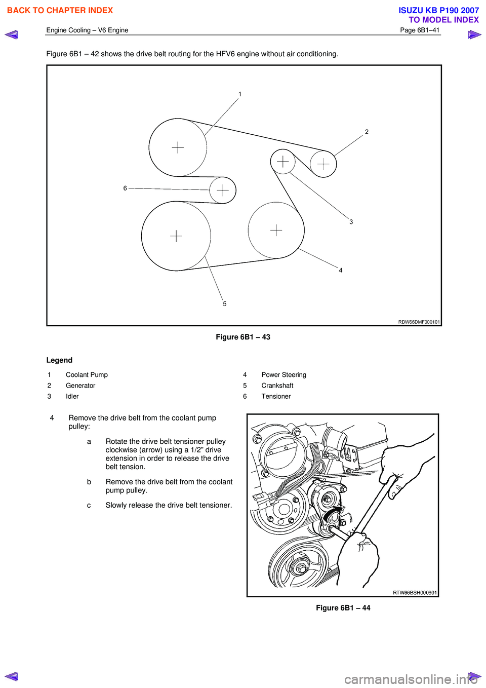
Figure 6B1 – 42 shows the drive belt routing for the HFV6 engine without air conditioning.
Figure 6B1 – 43
Legend
1 Coolant Pump
2 Generator
3 Idler 4 Power Steering
5 Crankshaft
6 Tensioner
4 Remove the drive belt from the coolant pump pulley:
a Rotate the drive belt tensioner pulley clockwise (arrow) using a 1/2” drive
extension in order to release the drive
belt tension.
b Remove the drive belt from the coolant pump pulley.
c Slowly release the drive belt tensioner.
Figure 6B1 – 44
BACK TO CHAPTER INDEX
TO MODEL INDEX
ISUZU KB P190 2007