2007 ISUZU KB P190 steering
[x] Cancel search: steeringPage 2214 of 6020
6E–44 ENGINE DRIVEABILITY AND EMISSIONS
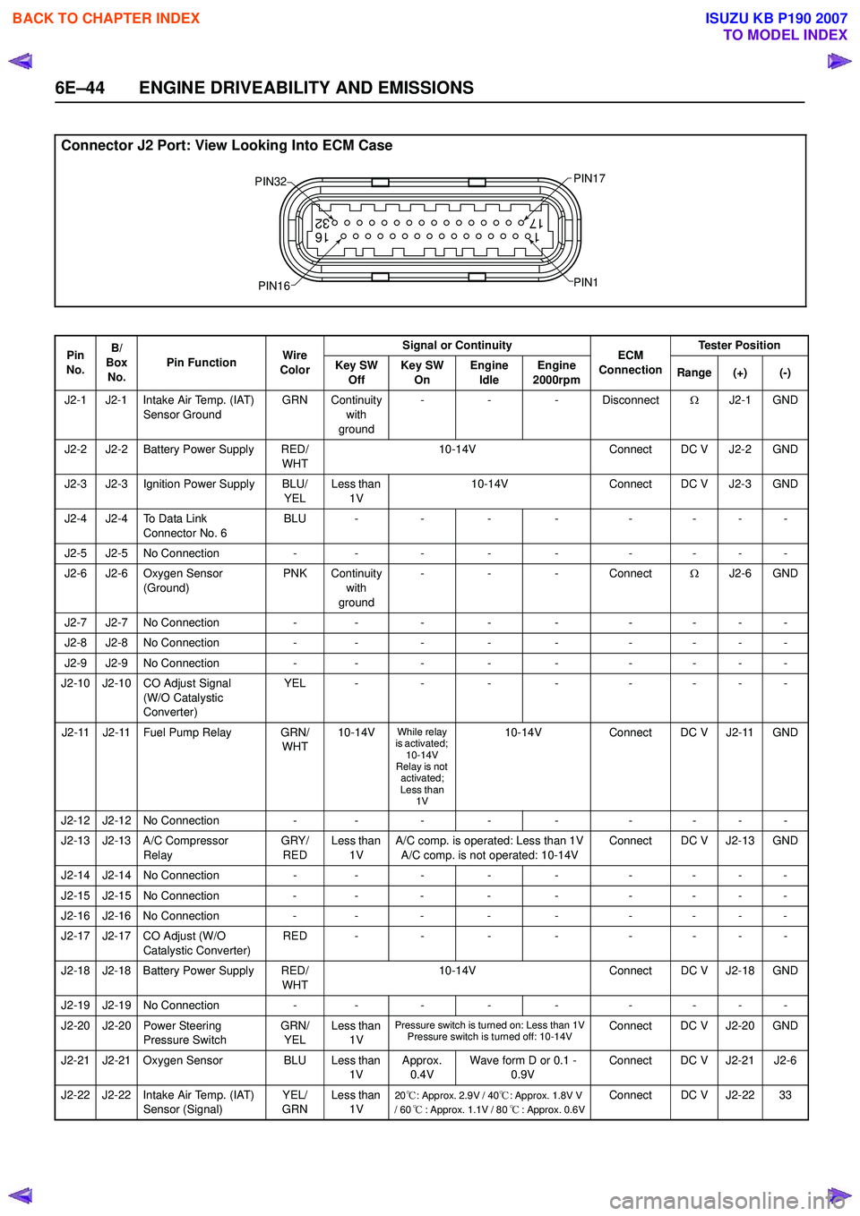
Connector J2 Port: View Looking Into ECM Case
1
17 16
32
PIN32
PIN1
PIN17
PIN16
Pin
No. B/
Box No. Pin Function
Wire
Color Signal or Continuity
ECM
Connection Tester Position
Key SW Off Key SW
On Engine
Idle Engine
2000rpm Range (+) (-)
J2-1 J2-1 Intake Air Temp. (IAT) Sensor Ground GRN Continuity
with
ground -
- - Disconnect ΩJ2-1 GND
J2-2 J2-2 Battery Power Supply RED/ WHT10-14V
Connect DC V J2-2 GND
J2-3 J2-3 Ignition Power Supply BLU/ YELLess than
1V 10-14V
Connect DC V J2-3 GND
J2-4 J2-4 To Data Link Connector No. 6 BLU -
-- - -- - -
J2-5 J2-5 No Connection -- - - - -- - -
J2-6 J2-6 Oxygen Sensor (Ground) PNK Continuity
with
ground -
- - Connect ΩJ2-6 GND
J2-7 J2-7 No Connection -- - - - -- - -
J2-8 J2-8 No Connection -- - - - -- - -
J2-9 J2-9 No Connection -- - - - -- - -
J2-10 J2-10 CO Adjust Signal (W/O Catalystic
Converter) YEL -
-- - -- - -
J2-11 J2-11 Fuel Pump Relay GRN/ WHT10-14V
While relay
is activated; 10-14V
Relay is not
activated;
Less than 1V10-14V Connect DC V J2-11 GND
J2-12 J2-12 No Connection -- - - - -- - -
J2-13 J2-13 A/C Compressor Relay GRY/
RED Less than
1V A/C comp. is operated: Less than 1V
A/C comp. is not operated: 10-14V Connect DC V J2-13 GND
J2-14 J2-14 No Connection -- - - - -- - -
J2-15 J2-15 No Connection -- - - - -- - -
J2-16 J2-16 No Connection -- - - - -- - -
J2-17 J2-17 CO Adjust (W/O Catalystic Converter) RED -
-- - -- - -
J2-18 J2-18 Battery Power Supply RED/ WHT10-14V
Connect DC V J2-18 GND
J2-19 J2-19 No Connection -- - - - -- - -
J2-20 J2-20 Power Steering Pressure Switch GRN/
YEL Less than
1V
Pressure switch is turned on: Less than 1VPressure switch is turned off: 10-14VConnect DC V J2-20 GND
J2-21 J2-21 Oxygen Sensor BLU Less than 1VApprox.
0.4V Wave form D or 0.1 -
0.9V Connect DC V J2-21 J2-6
J2-22 J2-22 Intake Air Temp. (IAT) Sensor (Signal) YEL/
GRN Less than
1V
20℃: Approx. 2.9V / 40 ℃: Approx. 1.8V V
/ 60 ℃: Approx. 1.1V / 80 ℃: Approx. 0.6VConnect DC V J2-22 33
BACK TO CHAPTER INDEX
TO MODEL INDEX
ISUZU KB P190 2007
Page 2218 of 6020
6E–48 ENGINE DRIVEABILITY AND EMISSIONS
GENERAL DESCRIPTION FOR ECM AND
SENSORS
Engine Control Module (ECM)
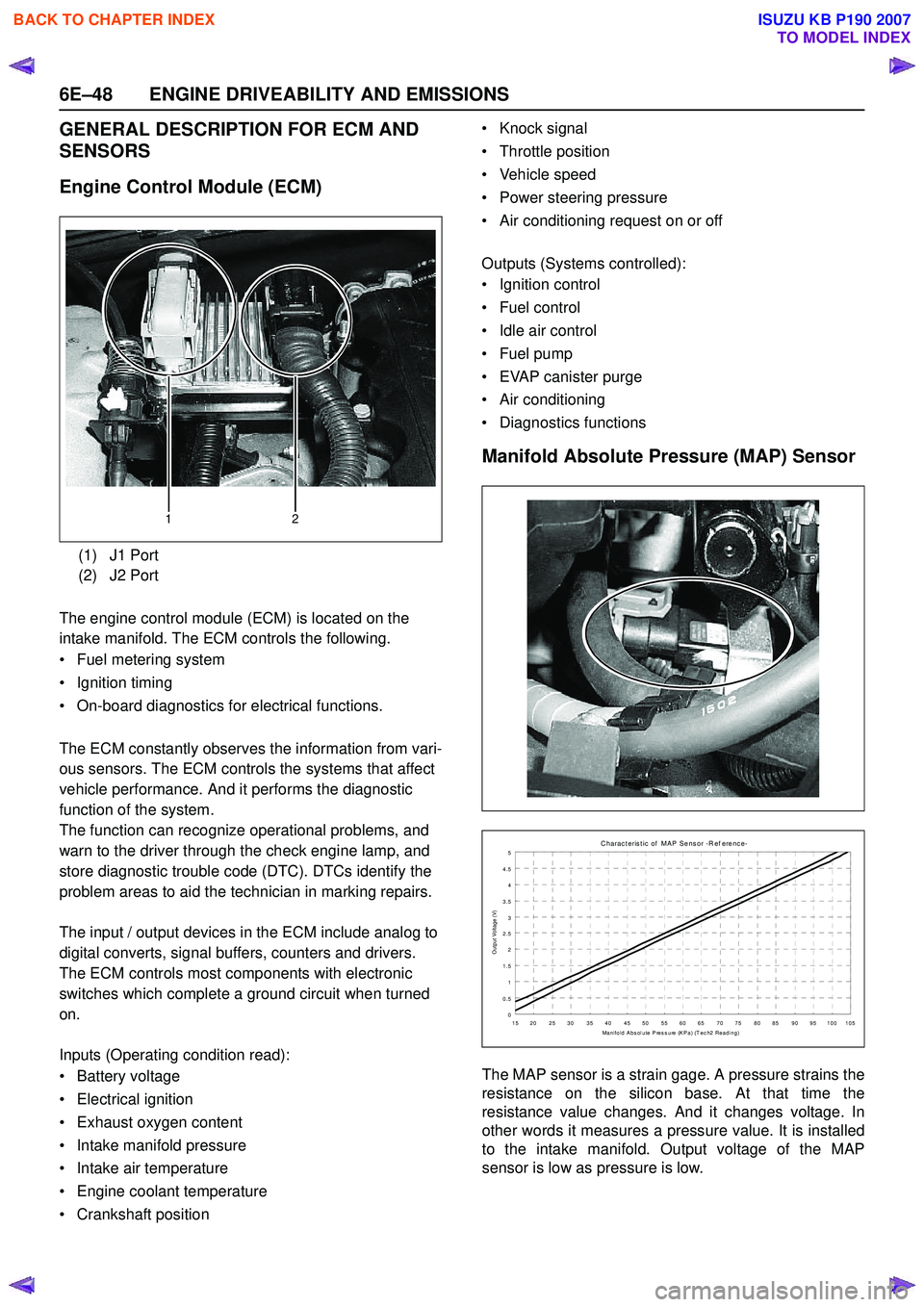
The engine control module (ECM) is located on the
intake manifold. The ECM controls the following.
• Fuel metering system
• Ignition timing
• On-board diagnostics for electrical functions.
The ECM constantly observes the information from vari-
ous sensors. The ECM controls the systems that affect
vehicle performance. And it performs the diagnostic
function of the system.
The function can recognize operational problems, and
warn to the driver through the check engine lamp, and
store diagnostic trouble code (DTC). DTCs identify the
problem areas to aid the technician in marking repairs.
The input / output devices in the ECM include analog to
digital converts, signal buffers, counters and drivers.
The ECM controls most components with electronic
switches which complete a ground circuit when turned
on.
Inputs (Operating condition read):
• Battery voltage
• Electrical ignition
• Exhaust oxygen content
• Intake manifold pressure
• Intake air temperature
• Engine coolant temperature
• Crankshaft position • Knock signal
• Throttle position
• Vehicle speed
• Power steering pressure
• Air conditioning request on or off
Outputs (Systems controlled):
• Ignition control
• Fuel control
• Idle air control
• Fuel pump
• EVAP canister purge
• Air conditioning
• Diagnostics functions
Manifold Absolute Pressure (MAP) Sensor
The MAP sensor is a strain gage. A pressure strains the
resistance on the silicon base. At that time the
resistance value changes. And it changes voltage. In
other words it measures a pressure value. It is installed
to the intake manifold. Output voltage of the MAP
sensor is low as pressure is low.
(1) J1 Port
(2) J2 Port
12
C harac t eris t ic of MAP Sens or -R ef erenc e-
0
0.5 1
1.5 2
2.5
3
3.5 4
4.5 5
15 20 25 30 35 40 45 50 55 60 65 70 75 80 85 90 95 100 105 Manifold Abs olute Press ure (KPa) (T ec h2 Reading)
Output Voltage (V)
BACK TO CHAPTER INDEX
TO MODEL INDEX
ISUZU KB P190 2007
Page 2219 of 6020

ENGINE DRIVEABILITY AND EMISSIONS 6E–49
Throttle Position Sensor (TPS)
The TPS is a potentiometer connected to throttle shaft
on the throttle body.
The engine control module (ECM) monitors the voltage
on the signal line and calculates throttle position. As the
throttle valve angle is changed when accelerator pedal
moved. The TPS signal also changed at a moved
throttle valve. As the throttle valve opens, the output
increases so that the output voltage should be high.
The throttle body has a throttle plate to control the
amount of the air delivered to the engine.
Engine coolant is directed through a coolant cavity in
the throttle body to warm the throttle valve and to
prevent icing.
Idle Air Control (IAC) Valve
The idle air control valve (IAC) valve is two directional
and gives 2-way control. With power supply to the coils
controlled steps by the engine control module (ECM),
the IAC valve's pintle is moved to adjust idle speed,
raising it for fast idle when cold or there is extra load
from the air conditioning or power steering.
By moving the pintle in (to decrease air flow) or out (to
increase air flow), a controlled amount of the air can
move around the throttle plate. If the engine speed is
too low, the engine control module (ECM) will retract the
IAC pintle, resulting in more air moving past the throttle
plate to increase the engine speed.
If the engine speed is too high, the engine control
module (ECM) will extend the IAC pintle, allowing less
air to move past the throttle plate, decreasing the
engine speed.
The IAC pintle valve moves in small step called counts.
During idle, the proper position of the IAC pintle is
calculated by the engine control module (ECM) based
on battery voltage, coolant temperature, engine load,
and engine speed.
If the engine speed drops below a specified value, and
the throttle plate is closed, the engine control module
(ECM) senses a near-stall condition. The engine control
module (ECM) will then calculate a new IAC pintle valve
position to prevent stalls.
If the IAC valve is disconnected and reconnected with
the engine running, the idle speed will be wrong. In this
case, the IAC must be reset. The IAC resets when the
key is cycled “On” then “Off”. When servicing the IAC, it
should only be disconnected or connected with the
ignition “Off”.
The position of the IAC pintle valve affects engine start-
up and the idle characteristic of the vehicle.
If the IAC pintle is fully open, too much air will be
allowed into the manifold. This results in high idle
speed, along with possible hard starting and lean air/
fuel ratio.
(1) Throttle Position Sensor
(2) Idle Air Control (IAC) Valve
1
2
C harac teris t ic of TPS -R ef erenc e-
0
0.5
1
1.5 2
2.5
3
3.5 4
4.5 5
0 10 2030 405060 7080 90100 Throt t le Angle (% ) (Tec h2 R eading)
Output Voltage (V)
StepCoilAB CDCoil A H igh
(ECM J1-28) On On
Coil A Low
(ECM J1-30) On On
Coil B H igh
(ECM J1-13) On On
Coil B Low
(ECM J1-29) On On
(IAC Valve Close Direction)
(IAC Valve Open Direction)
BACK TO CHAPTER INDEX
TO MODEL INDEX
ISUZU KB P190 2007
Page 2438 of 6020
6E–268 ENGINE DRIVEABILITY AND EMISSIONS
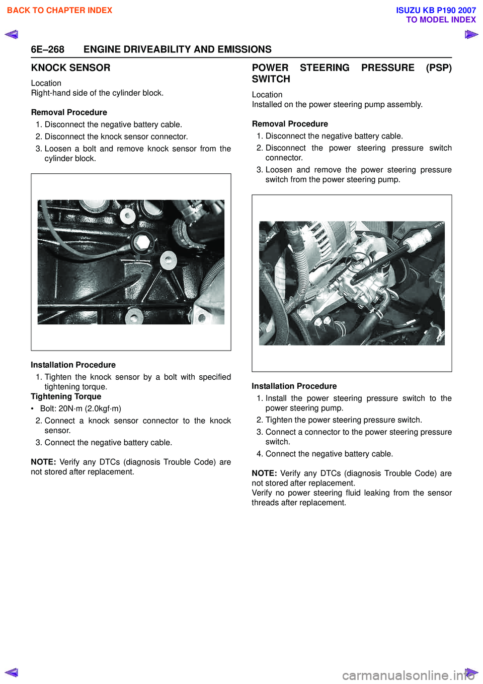
KNOCK SENSOR
Location
Right-hand side of the cylinder block.
Removal Procedure 1. Disconnect the negative battery cable.
2. Disconnect the knock sensor connector.
3. Loosen a bolt and remove knock sensor from the cylinder block.
Installation Procedure 1. Tighten the knock sensor by a bolt with specified tightening torque.
Tightening Torque
• Bolt: 20N·m (2.0kgf·m) 2. Connect a knock sensor connector to the knock sensor.
3. Connect the negative battery cable.
NOTE: Verify any DTCs (diagnosis Trouble Code) are
not stored after replacement.
POWER STEERING PRESSURE (PSP)
SWITCH
Location
Installed on the power steering pump assembly.
Removal Procedure 1. Disconnect the negative battery cable.
2. Disconnect the power steering pressure switch connector.
3. Loosen and remove the power steering pressure switch from the power steering pump.
Installation Procedure 1. Install the power steering pressure switch to the power steering pump.
2. Tighten the power steering pressure switch.
3. Connect a connector to the power steering pressure switch.
4. Connect the negative battery cable.
NOTE: Verify any DTCs (diagnosis Trouble Code) are
not stored after replacement.
Verify no power steering fluid leaking from the sensor
threads after replacement.
BACK TO CHAPTER INDEX
TO MODEL INDEX
ISUZU KB P190 2007
Page 2482 of 6020
Engine Mechanical – V6 Page 6A1–3
Definition .......................................................................................................................................................... 50
Diagnostic Aids................................................................................................................................................. 50
Test Description ............................................................................................................... ................................ 50
Diagnostic Table............................................................................................................................................... 51
Drive Belt Excessive Wear ...................................................................................................... ............................ 51
Definition .......................................................................................................................................................... 51
Diagnostic Aids................................................................................................................................................. 52
Test Description ............................................................................................................... ................................ 52
Diagnostic Table............................................................................................................................................... 52
Accessory Drive Belt Tensioner Diagnosis ....................................................................................... ................ 52
Diagnostic Table............................................................................................................................................... 52
3 Minor Service Operations ....................................................................................................... .............53
3.1 Engine Oil ............................................................................................................................................................. 54
Check .................................................................................................................................................................... 54
Replace ........................................................................................................................ ......................................... 54
Pressure Check ................................................................................................................. ................................... 55
3.2 Oil Filter Cartridge ............................................................................................................................................... 56
Replace ................................................................................................................................................................. 56
3.3 Oil Filter Adaptor............................................................................................................. ..................................... 57
Remove ................................................................................................................................................................. 57
Reinstall ................................................................................................................................................................ 57
3.4 Oil Level Indicator Tube ....................................................................................................... ............................... 58
Remove ............................................................................................................................................................ 58
Reinstall ........................................................................................................................................................... 58
3.5 Accessory Drive Belt ........................................................................................................... ................................ 59
RWD Vehicle ......................................................................................................................................................... 59
Remove ............................................................................................................................................................ 59
Reinstall ........................................................................................................................................................... 59
3.6 Accessory Drive Belt Idler Pulley .............................................................................................. ......................... 60
Remove ............................................................................................................................................................ 60
Reinstall ........................................................................................................................................................... 60
3.7 Accessory Drive Belt Tensioner Assembly ........................................................................................ ............... 61
Remove ............................................................................................................................................................ 61
Reinstall ........................................................................................................................................................... 61
3.8 Power Steering Pump Bracket .................................................................................................... ........................ 62
Remove ................................................................................................................................................................. 62
Reinstall ................................................................................................................................................................ 62
3.9 Upper Intake Manifold.......................................................................................................... ................................ 62
Remove ................................................................................................................................................................. 63
Disassemble ......................................................................................................................................................... 66
Clean ..................................................................................................................................................................... 66
Inspect .................................................................................................................................................................. 66
Reassemble .......................................................................................................................................................... 67
Reinstall ...................................................................................................................... .......................................... 67
3.10 Intake Manifold Assembly – Complete............................................................................................ ................... 68
Remove ................................................................................................................................................................. 68
Disassemble ......................................................................................................................................................... 72
Clean ..................................................................................................................................................................... 73
Inspect .................................................................................................................................................................. 73
Reassemble .......................................................................................................................................................... 74
Reinstall ...................................................................................................................... .......................................... 74
3.11 Exhaust Manifold Assembly ...................................................................................................... ......................... 75
Remove ................................................................................................................................................................. 75
Inspect .................................................................................................................................................................. 77
Reinstall ................................................................................................................................................................ 77
3.12 Camshaft Cover ................................................................................................................. .................................. 79
Remove ................................................................................................................................................................. 79
Clean and Inspect .............................................................................................................. .................................. 81
BACK TO CHAPTER INDEX
TO MODEL INDEX
ISUZU KB P190 2007
Page 2519 of 6020
Engine Mechanical – V6 Page 6A1–40
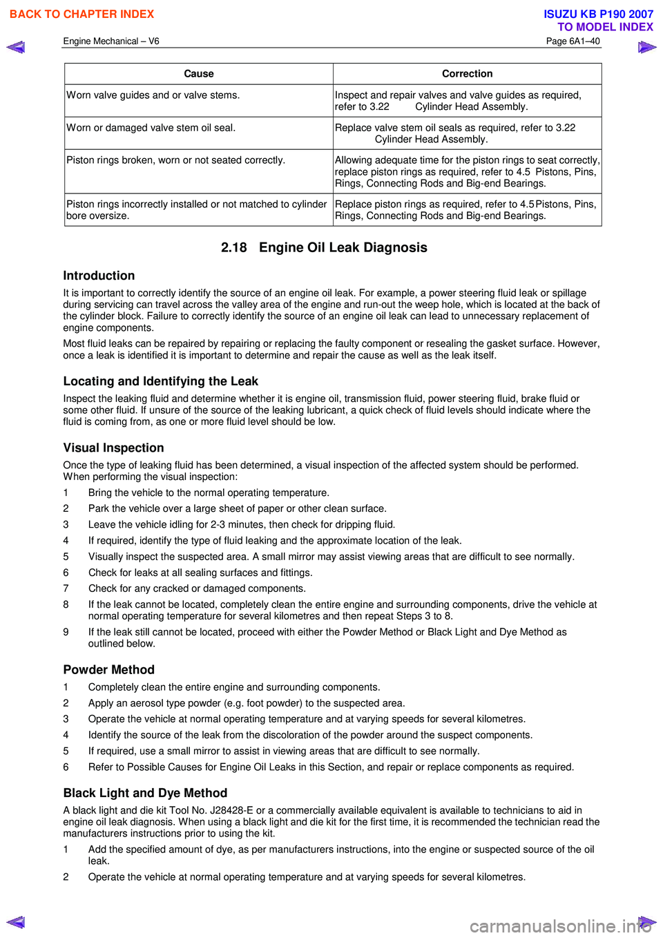
Cause Correction
W orn valve guides and or valve stems. Inspect and repair valves and valve guides as required,
refer to 3.22 Cylinder Head Assembly.
W orn or damaged valve stem oil seal. Replace valve stem oil seals as required, refer to 3.22
Cylinder Head Assembly.
Piston rings broken, worn or not seated correctly. Allowing adequate time for the piston rings to seat correctly,
replace piston rings as required, refer to 4.5 Pistons, Pins,
Rings, Connecting Rods and Big-end Bearings.
Piston rings incorrectly installed or not matched to cylinder
bore oversize. Replace piston rings as required, refer to 4.5 Pistons, Pins,
Rings, Connecting Rods and Big-end Bearings.
2.18 Engine Oil Leak Diagnosis
Introduction
It is important to correctly identify the source of an engine oil leak. For example, a power steering fluid leak or spillage
during servicing can travel across the valley area of the engine and run-out the weep hole, which is located at the back of
the cylinder block. Failure to correctly identify the source of an engine oil leak can lead to unnecessary replacement of
engine components.
Most fluid leaks can be repaired by repairing or replacing the faulty component or resealing the gasket surface. However,
once a leak is identified it is important to determine and repair the cause as well as the leak itself.
Locating and Identifying the Leak
Inspect the leaking fluid and determine whether it is engine oil, transmission fluid, power steering fluid, brake fluid or
some other fluid. If unsure of the source of the leaking lubricant, a quick check of fluid levels should indicate where the
fluid is coming from, as one or more fluid level should be low.
Visual Inspection
Once the type of leaking fluid has been determined, a visual inspection of the affected system should be performed.
W hen performing the visual inspection:
1 Bring the vehicle to the normal operating temperature.
2 Park the vehicle over a large sheet of paper or other clean surface.
3 Leave the vehicle idling for 2-3 minutes, then check for dripping fluid.
4 If required, identify the type of fluid leaking and the approximate location of the leak.
5 Visually inspect the suspected area. A small mirror may assist viewing areas that are difficult to see normally.
6 Check for leaks at all sealing surfaces and fittings.
7 Check for any cracked or damaged components.
8 If the leak cannot be located, completely clean the entire engine and surrounding components, drive the vehicle at normal operating temperature for several kilometres and then repeat Steps 3 to 8.
9 If the leak still cannot be located, proceed with either the Powder Method or Black Light and Dye Method as outlined below.
Powder Method
1 Completely clean the entire engine and surrounding components.
2 Apply an aerosol type powder (e.g. foot powder) to the suspected area.
3 Operate the vehicle at normal operating temperature and at varying speeds for several kilometres.
4 Identify the source of the leak from the discoloration of the powder around the suspect components.
5 If required, use a small mirror to assist in viewing areas that are difficult to see normally.
6 Refer to Possible Causes for Engine Oil Leaks in this Section, and repair or replace components as required.
Black Light and Dye Method
A black light and die kit Tool No. J28428-E or a commercially available equivalent is available to technicians to aid in
engine oil leak diagnosis. W hen using a black light and die kit for the first time, it is recommended the technician read the
manufacturers instructions prior to using the kit.
1 Add the specified amount of dye, as per manufacturers instructions, into the engine or suspected source of the oil leak.
2 Operate the vehicle at normal operating temperature and at varying speeds for several kilometres.
BACK TO CHAPTER INDEX
TO MODEL INDEX
ISUZU KB P190 2007
Page 2524 of 6020
Engine Mechanical – V6 Page 6A1–45
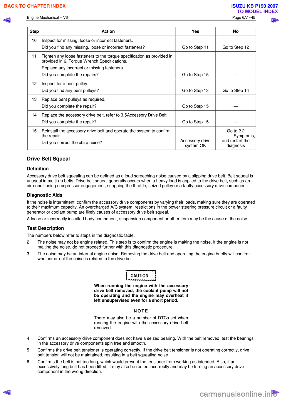
Step Action Yes No
10 Inspect for missing, loose or incorrect fasteners.
Did you find any missing, loose or incorrect fasteners? Go to Step 11 Go to Step 12
11 Tighten any loose fasteners to the torque specification as provided in
provided in 6. Torque W rench Specifications.
Replace any incorrect or missing fasteners.
Did you complete the repairs? Go to Step 15 —
12 Inspect for a bent pulley. Did you find any bent pulleys? Go to Step 13 Go to Step 14
13 Replace bent pulleys as required. Did you complete the repair? Go to Step 15 —
14 Replace the accessory drive belt, refer to 3.5 Accessory Drive Belt.
Did you complete the repair? Go to Step 15 —
15 Reinstall the accessory drive belt and operate the system to confirm the repair.
Did you correct the chirp noise? Accessory drive
system OK Go to 2.2
Symptoms, and restart the
diagnosis
Drive Belt Squeal
Definition
Accessory drive belt squealing can be defined as a loud screeching noise caused by a slipping drive belt. Belt squeal is
unusual in multi-rib belts. Drive belt squeal generally occurs when a heavy load is applied to the drive belt, such as an
air-conditioning compressor engagement, snapping the throttle, seized pulley or a faulty accessory drive component.
Diagnostic Aids
If the noise is intermittent, confirm the accessory drive components by varying their loads, making sure they are operated
to their maximum capacity. An overcharged A/C system, restrictions in the power steering pressure circuit or a faulty
generator or coolant pump are likely causes of accessory drive belt squeal.
A loose or incorrectly installed body component, suspension component or other item may be the cause of the noise.
Test Description
The numbers below refer to steps in the diagnostic table.
2 The noise may not be engine related. This step is to confirm the engine is making the noise. If the engine is not making the noise, do not proceed further with this diagnostic procedure.
3 The noise may be an internal engine noise. Removing the drive belt and operating the engine briefly will confirm whether or not the noise is related to the drive belt.
CAUTION
When running the engine with the accessory
drive belt removed, the coolant pump will not
be operating and the engine may overheat if
left unsupervised even for a short period.
NOTE
There may also be a number of DTCs set when
running the engine with the accessory drive belt
removed.
4 Confirms an accessory drive component does not have a seized bearing. W ith the belt removed, test the bearings in the accessory drive components spin free and smooth.
5 Confirms the drive belt tensioner is operating correctly. If the drive belt tensioner is not operating correctly, drive belt tension will not be maintained, resulting in a belt squealing noise
6 Confirms the belt is not too long, which would prevent the tensioner from working as intended. Also, if an excessively long belt has been fitted, it may also be routed incorrectly and may be turning an accessory drive
component in the wrong direction.
BACK TO CHAPTER INDEX
TO MODEL INDEX
ISUZU KB P190 2007
Page 2525 of 6020
Engine Mechanical – V6 Page 6A1–46
7 Misalignment of the pulleys may be caused by one of the following:
• Incorrect mounting of an accessory drive component,
• Incorrect installation of an accessory drive pulley or,
• Bent or damaged pulley.
Test for a misaligned pulley using a straight edge in the pulley grooves across 2 or 3 pulleys. If a misaligned pulley is found, refer to the relevant component service information for the correct installation and removal procedures.
8 This test is to confirm the pulleys are the correct diameter and/or width. Using a known good vehicle, compare the pulley sizes.
Diagnostic Table
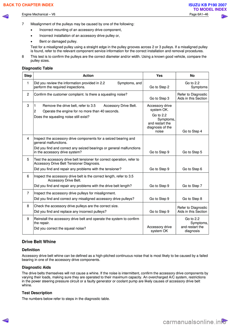
Step Action Yes No
1 Did you review the information provided in 2.2 Symptoms, and
perform the required inspections. Go to Step 2 Go to 2.2
Symptoms
2 Confirm the customer complaint. Is there a squealing noise? Go to Step 3 Refer to Diagnostic
Aids in this Section
3 1 Remove the drive belt, refer to 3.5 Accessory Drive Belt.
2 Operate the engine for no more than 40 seconds.
Does the squealing noise still exist? Accessory drive
system OK.
Go to 2.2
Symptoms, and restart the
diagnosis of the noise Go to Step 4
4 Inspect the accessory drive components for a seized bearing and
general malfunctions.
Did you find and correct any seized bearings or general malfunctions
in the accessory drive system? Go to Step 9 Go to Step 5
5 Test the accessory drive belt tensioner for correct operation, refer to
Accessory Drive Belt Tensioner Diagnosis.
Did you find and repair any problems with the tensioner? Go to Step 9 Go to Step 6
6 Inspect the accessory drive belt is the correct length, refer to 3.5
Accessory Drive Belt.
Did you find and repair any problems with the drive belt length? Go to Step 9 Go to Step 7
7 Inspect the accessory drive pulleys for misalignment.
Did you find and correct any misaligned accessory drive pulleys? Go to Step 9 Go to Step 8
8 Check the accessory drive pulleys are the correct size. Did you find and replace any incorrect pulleys? Go to Step 9 Refer to Diagnostic
Aids in this Section
9 Reinstall the accessory drive belt and operate the system to confirm
the repair.
Did you correct the squeal noise? Accessory drive
system OK Go to 2.2
Symptoms, and restart the diagnosis
Drive Belt Whine
Definition
Accessory drive belt whine can be defined as a high-pitched continuous noise that is most likely to be caused by a failed
bearing in one of the accessory drive components.
Diagnostic Aids
The drive belts themselves will not cause a whine. If the noise is intermittent, confirm the accessory drive components by
varying their loads, making sure they are operated to their maximum capacity. An overcharged A/C system, restrictions
in the power steering pressure circuit or a faulty generator or coolant pump are likely causes of accessory drive belt
whine.
Test Description
The numbers below refer to steps in the diagnostic table.
BACK TO CHAPTER INDEX
TO MODEL INDEX
ISUZU KB P190 2007