2007 ISUZU KB P190 steering
[x] Cancel search: steeringPage 5668 of 6020
SUPPLEMENTAL RESTRAINT SYSTEM 9A-33
Inspections Required After An Accident
CAUTION: Certain SRS components must be
replaced after a frontal crash involving air bag
deployment.
In all types of accidents regardless of “Air Bag”
deployment, visually inspect all of the following
components and replace as required:
– Driver air bag assembly
– Passenger air bag assembly
– Steering wheel
– SRS coil assembly
– Steering column
– Knee bolster and instrument panel mounting attachments
– Driver seat and belt
– Passenger seat and belt
– SRS control unit
The SRS control unit should always be checked
according to “SRS Control Unit Replacement
Guidelines.”
CAUTION: Refer to “SRS control unit Replacement
Guidelines” below for important information on
SRS control unit replacement in both deployment
and non–deployment crashes.
Inspect the SRS coil assembly wiring and the steering
wheel for any sign of scorching, melting, or damage
due to excessive heat. If the coil assembly wire o
r
steering wheel is damaged, replace them. The
steering column and wheel must be dimensionall
y
checked to determine if they are damaged. Refer to
“steering wheel” in this manual.
Never use SRS parts from another vehicle. This does
not include remanufactured parts purchased from an
authorized ISUZU/GM Retailer; they may be used fo
r
SRS repairs.
Do not attempt to repair the SRS control unit, the SRS
harness, the SRS coil assembly, the air bag assembly,
the steering wheel, or the steering column. Service o
f
these items is replacement only. Verify replacement
part numbers.
CAUTION: Proper operation of the SRS control
unit and the supplemental restraint system (SRS)
requires that any repairs to the vehicle structure
return it to its original production configuration.
SRS Connectors
CAUTION: The special yellow color connectors are
used for the supplemental restraint system-air bag
circuit. When removing the cable harness, do not
pull the cables otherwise cable disconnection may
occur. When connecting the SRS connector, insert
the connector completely. Imperfect locking may
cause malfunction of the SRS circuit.
Removal
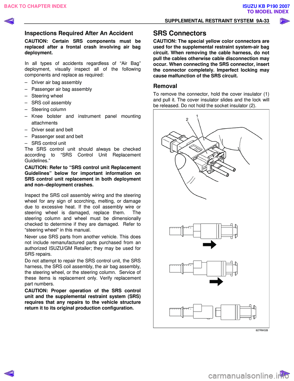
To remove the connector, hold the cover insulator (1)
and pull it. The cover insulator slides and the lock will
be released. Do not hold the socket insulator (2).
827RW 028
BACK TO CHAPTER INDEX TO MODEL INDEXISUZU KB P190 2007
Page 5672 of 6020
SUPPLEMENTAL RESTRAINT SYSTEM 9A-37
Driver Air Bag Assembly
Service Precautions
WARNING: SAFETY PRECAUTIONS MUST BE
FOLLOWED WHEN HANDLING A DEPLOYED AIR
BAG ASSEMBLY. AFTER DEPLOYMENT, THE AIR
BAG ASSEMBLY SURFACE MAY CONTAIN
A
SMALL AMOUNT OF SODIUM HYDROXIDE, A BY–
PRODUCT OF THE DEPLOYMENT REACTION
THAT IS IRRITATING TO THE SKIN AND EYES.
MOST OF THE POWDER ON THE AIR BAG
ASSEMBLY IS HARMLESS. AS A PRECAUTION,
WEAR GLOVES AND SAFETY GLASSES WHEN
HANDLING A DEPLOYED AIR BAG ASSEMBLY,
AND WASH YOUR HANDS WITH MILD SOAP AND
WATER AFTERWARDS.
WARNING: WHEN CARRYING A LIVE AIR BAG
ASSEMBLY, MAKE SURE THE BAG AND TRIM
COVER ARE POINTED AWAY FROM YOU. NEVER
CARRY THE AIR BAG ASSEMBLY BY THE WIRES
OR CONNECTOR ON THE UNDERSIDE OF THE
MODULE. IN THE CASE OF AN ACCIDENTAL
DEPLOYMENT, THE BAG WILL THEN DEPLOY
WITH MINIMAL CHANCE OF INJURY. WHEN
PLACING ALIVE AIR BAG ASSEMBLY ON
A
BENCH OR OTHER SURFACE, ALWAYS FACE
THE BAG AND TRIM COVER UP, AWAY FROM THE
SURFACE. NEVER REST A STEERING COLUMN
ASSEMBLY ON THE STEERING WHEEL WITH THE
AIR BAG ASSEMBLY FACE DOWN AND COLUMN
VERTICAL. THIS IS NECESSARY SO THAT A FREE
SPACE IS PROVIDED TO ALLOW THE AIR BAG
ASSEMBLY TO EXPAND IN THE UNLIKELY EVENT
OF ACCIDENTAL DEPLOYMENT. OTHERWISE,
PERSONAL INJURY COULD RESULT.
NOTE: In the event deployment has occurred, inspect
the coil assembly wire for any signs of scorching,
melting or any other damage due to excessive heat. I
f
the coil has been damaged, replace it.
Removal
Refer to the “Inflator Module” in the “Power-Assisted
Steering System” section.
Installation
Refer to the “Inflator Module” in the “Power-Assisted
Steering System” section.
BACK TO CHAPTER INDEX
TO MODEL INDEXISUZU KB P190 2007
Page 5673 of 6020
9A-38 SUPPLEMENTAL RESTRAINT SYSTEM
Steering Wheel
Service Precautions
WARNING: SAFETY PRECAUTIONS MUST BE
FOLLOWED WHEN HANDLING A DEPLOYED AIR
BAG ASSEMBLY. AFTER DEPLOYMENT, THE AIR
BAG ASSEMBLY SURFACE MAY CONTAIN
A
SMALL AMOUNT OF SODIUM HYDROXIDE, A BY–
PRODUCT OF THE DEPLOYMENT REACTION
THAT IS IRRITATING TO THE SKIN AND EYES.
MOST OF THE POWDER ON THE AIR BAG
ASSEMBLY IS HARMLESS. AS A PRECAUTION,
WEAR GLOVES AND SAFETY GLASSES WHEN
HANDLING A DEPLOYED AIR BAG ASSEMBLY,
AND WASH YOUR HANDS WITH MILD SOAP AND
WATER AFTERWARDS.
WARNING: WHEN CARRYING A LIVE AIR BAG
ASSEMBLY, MAKE SURE THE BAG AND TRIM
COVER ARE POINTED AWAY FROM YOU. NEVER
CARRY AN AIR BAG ASSEMBLY BY THE WIRES
OR CONNECTOR ON THE UNDERSIDE OF THE
MODULE. IN THE CASE OF AN ACCIDENTAL
DEPLOYMENT, THE BAG WILL THEN DEPLOY
WITH MINIMAL CHANCE OF INJURY. WHEN
PLACING ALIVE AIR BAG ASSEMBLY ON
A
BENCH OR OTHER SURFACE, ALWAYS FACE
THE BAG AND TRIM COVER UP, AWAY FROM THE
SURFACE. NEVER REST A STEERING COLUMN
ASSEMBLY ON THE STEERING WHEEL WITH THE
AIR BAG ASSEMBLY FACE DOWN AND COLUMN
VERTICAL. THIS IS NECESSARY SO THAT A FREE
SPACE IS PROVIDED TO ALLOW THE AIR BAG
ASSEMBLY TO EXPAND IN THE UNLIKELY EVENT
OF ACCIDENTAL DEPLOYMENT. OTHERWISE,
PERSONAL INJURY COULD RESULT.
In the event deployment has occurred, inspect the coil
assembly wire for any signs of scorching, melting o
r
any other damage due to excessive heat. If the coil
has been damaged, replace it.
Removal
Refer to the “Steering W heel” in the “Power-Assisted
Steering System” section.
Installation
Refer to the “Steering W heel” in the “Power-Assisted
Steering W heel” section.
BACK TO CHAPTER INDEX
TO MODEL INDEXISUZU KB P190 2007
Page 5674 of 6020
SUPPLEMENTAL RESTRAINT SYSTEM 9A-39
SRS Coil Assembly
Service Precautions
WARNING: SAFETY PRECAUTIONS MUST BE
FOLLOWED WHEN HANDLING A DEPLOYED AIR
BAG ASSEMBLY. AFTER DEPLOYMENT, THE AIR
BAG ASSEMBLY SURFACE MAY CONTAIN
A
SMALL AMOUNT OF SODIUM HYDROXIDE, A BY–
PRODUCT OF THE DEPLOYMENT REACTION
THAT IS IRRITATING TO THE SKIN AND EYES.
MOST OF THE POWDER ON THE AIR BAG
ASSEMBLY IS HARMLESS. AS A PRECAUTION,
WEAR GLOVES AND SAFETY GLASSES WHEN
HANDLING A DEPLOYED AIR BAG ASSEMBLY,
AND WASH YOUR HANDS WITH MILD SOAP AND
WATER AFTERWARDS.
WARNING: WHEN CARRYING A LIVE AIR BAG
ASSEMBLY, MAKE SURE THE BAG AND TRIM
COVER ARE POINTED AWAY FROM YOU. NEVER
CARRY AN AIR BAG ASSEMBLY BY THE WIRES
OR CONNECTOR ON THE UNDERSIDE OF THE
MODULE. IN THE CASE OF AN ACCIDENTAL
DEPLOYMENT, THE BAG WILL THEN DEPLOY
WITH MINIMAL CHANCE OF INJURY. WHEN
PLACING ALIVE AIR BAG ASSEMBLY ON
A
BENCH OR OTHER SURFACE, ALWAYS FACE
THE BAG AND TRIM COVER UP, AWAY FROM THE
SURFACE. NEVER REST A STEERING COLUMN
ASSEMBLY ON THE STEERING WHEEL WITH THE
AIR BAG ASSEMBLY FACE DOWN AND COLUMN
VERTICAL. THIS IS NECESSARY SO THAT A FREE
SPACE IS PROVIDED TO ALLOW THE AIR BAG
ASSEMBLY TO EXPAND IN THE UNLIKELY EVENT
OF ACCIDENTAL DEPLOYMENT. OTHERWISE,
PERSONAL INJURY COULD RESULT.
NOTE: In the event deployment has occurred, inspect
the coil assembly wire for any signs of scorching,
melting or any other damage due to excessive heat. I
f
the coil has been damaged, replace it.
Removal
NOTE: The SRS coil is a part of the combination
switch assembly, which cannot be replaced separately.
Therefore, be sure not to remove the SRS coil from
the combination switch assembly.
Refer to the “Combination Switch” in the “Power-
Assisted Steering System” section.
Installation
Refer to the “Combination Switch” in the “Power-
Assisted Steering System” section.
BACK TO CHAPTER INDEX TO MODEL INDEXISUZU KB P190 2007
Page 5675 of 6020
9A-40 SUPPLEMENTAL RESTRAINT SYSTEM
Steering Column
Service Precautions
WARNING: SAFETY PRECAUTIONS MUST BE
FOLLOWED WHEN HANDLING A DEPLOYED AIR
BAG ASSEMBLY. AFTER DEPLOYMENT, THE AIR
BAG ASSEMBLY SURFACE MAY CONTAIN
A
SMALL AMOUNT OF SODIUM HYDROXIDE, A BY–
PRODUCT OF THE DEPLOYMENT REACTION
THAT IS IRRITATING TO THE SKIN AND EYES.
MOST OF THE POWDER ON THE AIR BAG
ASSEMBLY IS HARMLESS. AS A PRECAUTION,
WEAR GLOVES AND SAFETY GLASSES WHEN
HANDLING A DEPLOYED AIR BAG ASSEMBLY,
AND WASH YOUR HANDS WITH MILD SOAP AND
WATER AFTERWARDS.
WARNING: WHEN CARRYING A LIVE AIR BAG
ASSEMBLY, MAKE SURE THE BAG AND TRIM
COVER ARE POINTED AWAY FROM YOU. NEVER
CARRY AN AIR BAG ASSEMBLY BY THE WIRES
OR CONNECTOR ON THE UNDERSIDE OF THE
MODULE. IN THE CASE OF AN ACCIDENTAL
DEPLOYMENT, THE BAG WILL THEN DEPLOY
WITH MINIMAL CHANCE OF INJURY. WHEN
PLACING ALIVE AIR BAG ASSEMBLY ON
A
BENCH OR OTHER SURFACE, ALWAYS FACE
THE BAG AND TRIM COVER UP, AWAY FROM THE
SURFACE. NEVER REST A STEERING COLUMN
ASSEMBLY ON THE STEERING WHEEL WITH THE
AIR BAG ASSEMBLY FACE DOWN AND COLUMN
VERTICAL. THIS IS NECESSARY SO THAT A FREE
SPACE IS PROVIDED TO ALLOW THE AIR BAG
ASSEMBLY TO EXPAND IN THE UNLIKELY EVENT
OF ACCIDENTAL DEPLOYMENT. OTHERWISE,
PERSONAL INJURY COULD RESULT.
In the event deployment has occurred, inspect the coil
assembly wire for any signs of scorching, melting o
r
any other damage due to excessive heat. If the coil
has been damaged, replace it.
Removal
Refer to the “Steering Column” in the “Power-Assisted
Steering System” section.
Installation
Refer to the “Steering Column” in the “Power-Assisted
Steering System” section.
BACK TO CHAPTER INDEX
TO MODEL INDEXISUZU KB P190 2007
Page 5676 of 6020
SUPPLEMENTAL RESTRAINT SYSTEM 9A-41
Passenger Air Bag Assembly
Service Precautions
WARNING: SAFETY PRECAUTIONS MUST BE
FOLLOWED WHEN HANDLING A DEPLOYED AIR
BAG ASSEMBLY. AFTER DEPLOYMENT, THE AIR
BAG ASSEMBLY SURFACE MAY CONTAIN
A
SMALL AMOUNT OF SODIUM HYDROXIDE, A BY–
PRODUCT OF THE DEPLOYMENT REACTION
THAT IS IRRITATING TO THE SKIN AND EYES.
MOST OF THE POWDER ON THE AIR BAG
ASSEMBLY IS HARMLESS. AS A PRECAUTION,
WEAR GLOVES AND SAFETY GLASSES WHEN
HANDLING A DEPLOYED AIR BAG ASSEMBLY,
AND WASH YOUR HANDS WITH MILD SOAP AND
WATER AFTERWARDS.
WARNING: WHEN CARRYING A LIVE AIR BAG
ASSEMBLY, MAKE SURE THE BAG AND TRIM
COVER ARE POINTED AWAY FROM YOU. NEVER
CARRY AN AIR BAG ASSEMBLY BY THE WIRES
OR CONNECTOR ON THE UNDERSIDE OF THE
MODULE. IN THE CASE OF AN ACCIDENTAL
DEPLOYMENT, THE BAG WILL THEN DEPLOY
WITH MINIMAL CHANCE OF INJURY. WHEN
PLACING ALIVE AIR BAG ASSEMBLY ON
A
BENCH OR OTHER SURFACE, ALWAYS FACE
THE BAG AND TRIM COVER UP, AWAY FROM THE
SURFACE. NEVER REST A STEERING COLUMN
ASSEMBLY ON THE STEERING WHEEL WITH THE
AIR BAG ASSEMBLY FACE DOWN AND COLUMN
VERTICAL. THIS IS NECESSARY SO THAT A FREE
SPACE IS PROVIDED TO ALLOW THE AIR BAG
ASSEMBLY TO EXPAND IN THE UNLIKELY EVENT
OF ACCIDENTAL DEPLOYMENT. OTHERWISE,
PERSONAL INJURY COULD RESULT.
WARNING: IN THE EVENT DEPLOYMENT HAS
OCCURRED, INSPECT THE COIL ASSEMBLY
WIRE FOR ANY SIGNS OF SCORCHING, MELTING
OR ANY OTHER DAMAGE DUE TO EXCESSIVE
HEAT. IF THE COIL HAS BEEN DAMAGED,
REPLACE IT.
Removal
1. Disable the SRS. (Refer to “Disabling the SRS” in this section)
2. Remove the glove box.
3. Remove the glove box cover.
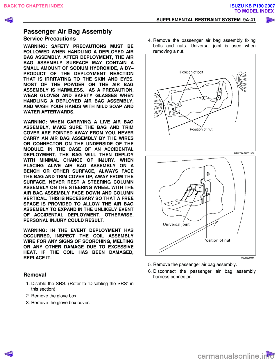
4. Remove the passenger air bag assembly fixing
bolts and nuts. Universal joint is used when
removing a nut.
RTW 79ASH001301
060R300044
5. Remove the passenger air bag assembly.
6. Disconnect the passenger air bag assembl
y
harness connector.
BACK TO CHAPTER INDEX TO MODEL INDEXISUZU KB P190 2007
Page 5679 of 6020

9A-44 SUPPLEMENTAL RESTRAINT SYSTEM
Main Data and Specifications
Fastener Tightening Specification
Application N·m kgf ·m lb ·ft/lb ·in
SRS control unit 7 0.7 61 lb ·in
Steering wheel fixing bolt 35 3.6 26 lb ·ft
Steering column (dash panel side fixing bolts) 20 2.0 14 lb ·ft
Steering column (Pedal bracket fixing bolt) 20 2.0 14 lb ·ft
Steering column (Universal joint fixing bolt) 31 3.2 23 lb ·ft
Passenger Air Bag fixing bolt & nut 8 0.8 69 lb ·in
BACK TO CHAPTER INDEX
TO MODEL INDEXISUZU KB P190 2007
Page 5682 of 6020
SUPPLEMENTAL RESTRAINT SYSTEM 9A-47
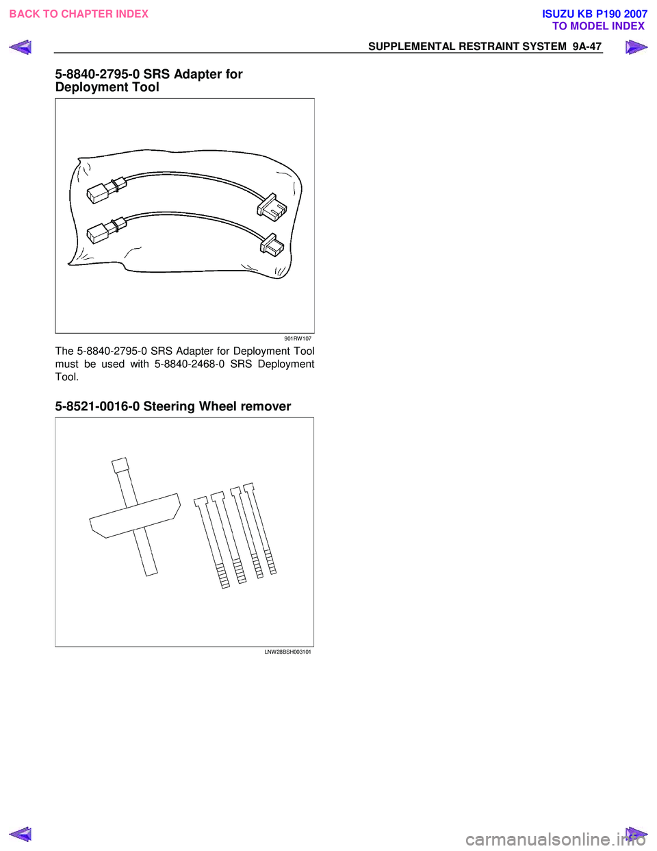
5-8840-2795-0 SRS Adapter for
Deployment Tool
901RW 107
The 5-8840-2795-0 SRS Adapter for Deployment Tool
must be used with 5-8840-2468-0 SRS Deployment
Tool.
5-8521-0016-0 Steering Wheel remover
LNW 28BSH003101
BACK TO CHAPTER INDEX
TO MODEL INDEXISUZU KB P190 2007