2007 ISUZU KB P190 key
[x] Cancel search: keyPage 4002 of 6020
7A2-36 TRANSMISSION CONTROL SYSTEM (AW30–40LE)
Trouble Code Clear Method:
If you have Tech 2:
Follow the procedure "DIAGNOSIS WITH TECH 2" in
this manual.
If you have no Tech 2:
Remove ECM (B) fuse (10A) for at least 10 seconds
with the ignition switched off.
NOTE:
If you clear the DTC you will not be able to read an
y
codes recorded during the last occurrence.
To use the DTC again to identify a problem, you will
need to reproduce the fault or the problem. This ma
y
require a new test drive or just turning the key switch on
(this depends on the nature of the fault).
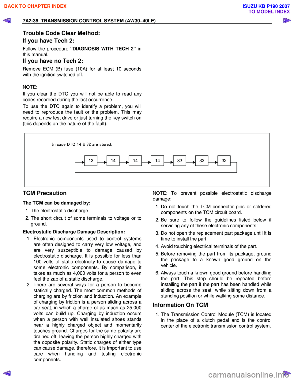
12141414323232
In case DTC 14 & 32 are stored:
TCM Precaution
The TCM can be damaged by:
1. The electrostatic discharge
2. The short circuit of some terminals to voltage or to
ground.
Electrostatic Discharge Damage Description: 1. Electronic components used to control systems are often designed to carry very low voltage, and
are very susceptible to damage caused b
y
electrostatic discharge. It is possible for less than
100 volts of static electricity to cause damage to
some electronic components. By comparison, it
takes as much as 4,000 volts for a person to even
feel the zap of a static discharge.
2. There are several ways for a person to become statically charged. The most common methods o
f
charging are by friction and induction. An example
of charging by friction is a person sliding across a
car seat, in which a charge of as much as 25,000
volts can build up. Charging by induction occurs
when a person with well insulated shoes stands
near a highly charged object and momentaril
y
touches ground. Charges for the same polarity are
drained off, leaving the person highly charged with
the opposite polarity. Static charges of either type
can cause damage, therefore, it is important to use
care when handling and testing electronic
components.
NOTE: To prevent possible electrostatic discharge
damage:
1. Do not touch the TCM connector pins or soldered
components on the TCM circuit board.
2. Be sure to follow the guidelines listed below i
f
servicing any of these electronic components:
3. Do not open the replacement part package until it is time to install the part.
4. Avoid touching electrical terminals of the part.
5. Before removing the part from its package, ground
the package to a known good ground on the
vehicle.
6.
Always touch a known good ground before handling
the part. This step should be repeated before
installing the part if the part has been handled while
sliding across the seat, while sitting down from a
standing position or while walking some distance.
Information On TCM
1. The Transmission Control Module (TCM) is located
in the place of a clutch pedal and is the control
center of the electronic transmission control system.
BACK TO CHAPTER INDEX
TO MODEL INDEX
ISUZU KB P190 2007
Page 4007 of 6020
TRANSMISSION CONTROL SYSTEM (AW30–40LE) 7A2-41
• All of the following conditions are met.
- Device Control is not operating
- Disable Normal Communication Service is receiving enable
- DTC Clear is not operating
Condition For Setting The DTC
W hen the TCM detects following conditions at 20 times
continuously.
• Ignition voltage is less than 9 volts for 1 second o
r
more continuously. (DTC P0562)
• Ignition voltage is more than 18 volts for 1 second o
r
more continuously. (DTC P0563)
Action Taken When The DTC Sets
• DTC stored.
Conditions For Clearing The DTC
• The DTC can be cleared from the TCM history by
using a scan tool.
• The DTC will be cleared from history when the
vehicle has achieved 40 warm-up cycles without a
failure reported.
•
After more than 1 second has elapsed after the
ignition key has been turned “ON”, short between
No.11 and No.4 (ground) of DLC (Data Link
Connector). Then, after 1 second, but within 6
seconds, discontinue shorting.
Diagnostic Aids
•
Inspect the wiring for poor electrical connection at the
TCM. Look for possible bent, backed out, deformed
or damaged terminals. Check for weak terminal
tension as well. Also check for a chafed wire that
could short to bare metal or other wiring.
Inspect for a broken wire inside the insulation.
• W hen diagnosing for a possible intermittent short o
r
open condition, move the wiring harness while
observing test equipment for a change.
Circuit/System Testing DTC P0562 or P0563
Step Action Value(s) YES NO
1
W as the On-Board Diagnostic (OBD) System Check
performed? — Go to
Step 2 Go to OBD
System Check
2 Using the 5-8840-0285-0 DMM, measure the battery voltage at the battery.
Is the battery voltage greater than the specified value? 11.5 V Go to
Step 3 Charge battery,
then go to Step 3
3 1. Install a scan tool.
2. Select “Ignition Volts” on a scan tool.
3. Start the engine and raise the engine speed to the specified value.
4. Load the electrical system by turning on the headlights, high blower, etc.
Is the ignition voltage approximately equal to the
specified value? More than
1000 rpm
9.0-18.0 V Go to
Step 4 Go to
Starting/
Charging
BACK TO CHAPTER INDEX
TO MODEL INDEX
ISUZU KB P190 2007
Page 4009 of 6020
TRANSMISSION CONTROL SYSTEM (AW30–40LE) 7A2-43
DTC P0602 (Flash Code 63)
Circuit Description
The Service Programming System (SPS) updates the
flash calibration files that are stored in a Transmission
Control Module (TCM). The calibration file
custom-tailors a module to a certain vehicle. The
calibration file contains data for things such as spark
curves and fuel control. W hen troubleshooting a
driveability problem, diagnosis may call fo
r
reprogramming the controller with newer calibration
information to correct a customer concern and Vehicle
Identification Number (VIN).
Condition for setting the DTC
W hen a VIN No. is not written into the TCM.
Action Taken When The DTC Sets
• DTC stored.
Conditions For Clearing The DTC
• The DTC can be cleared from the TCM history by
using a scan tool.
• The DTC will be cleared from history when the vehicle has achieved 40 warm-up cycles without a
failure reported.
•
After more than 1 second has elapsed after the
ignition key has been turned “ON”, short between
No.11 and No.4 (ground) of DLC (Data Link
Connector). Then, after 1 second, but within 6
seconds, discontinue shorting.
Diagnostic Aids
DTC P0602 is indicated when a VIN No. is not written
into the TCM.
A security lock is performed by SPS. And
not replace the TCM when DTC P0602 can repair b
y
SPS.
BACK TO CHAPTER INDEX
TO MODEL INDEX
ISUZU KB P190 2007
Page 4012 of 6020
7A2-46 TRANSMISSION CONTROL SYSTEM (AW30–40LE)
(2) Not emergency mode.
(3) All of the following conditions are met. • Device Control is not operating.
• Disable Normal Communication service is
receiving enable.
• DTC Clear is not operating.
Condition For Setting The DTC
DTC P0707
All of the following conditions are met for 30 seconds or
more continuously.
• All of the switches are “OFF”.
• Output revolution is more than 30 km/h (19 mph).
• Output revolution sensor is not detecting failure o
r
not deciding failure.
• The engine revolution is more than 1500 rpm.
DTC P0708
The following condition is met at 10 seconds
continuously.
• 2 switches or more are “ON” at the same time.
Action Taken When The DTC Sets
• No 3rd start mode.
• No slope control.
• No coast control.
• No output revolution sensor failure detection.
• No input revolution sensor failure detection.
• Keep oil temperature sensor OPEN failure detection accumulated timer.
• No T/F HI-Low SW failure detection.
• No shift solenoid functional failure detection.
• No L-up solenoid functional failure detection.
• No engine torque reduction at stall.
• Regard as D position. (DTC P0707)
• There is a priority in order of D, 3, 2, L, R, N, and P.
(DTC P0708)
• Check Trans “ON”.
• DTC stored.
• MIL request “ON”. (EURO 4 only)
Conditions For Clearing The DTC
•
The DTC can be cleared from the TCM history by
using a scan tool.
• The DTC will be cleared from history when the vehicle has achieved 40 warm-up cycles without a
failure reported.
•
After more than 1 second has elapsed after the
ignition key has been turned “ON”, short between
No.11 and No.4 (ground) of DLC (Data Link
Connector). Then, after 1 second, but within 6
seconds, discontinue shorting.
Diagnostic Aids
• Inspect the wiring for poor electrical connection at the
TCM. Look for possible bent, backed out, deformed
or damaged terminals. Check for weak terminal
tension as well. Also check for a chafed wire that
could short to bare metal or other wiring.
Inspect for a broken wire inside the insulation.
• W hen diagnosing for a possible intermittent short o
r
open condition, move the wiring harness while
observing test equipment for a change.
• Check neutral start switch for proper mounting and adjustment. (Refer to section 7A4 Components (1)
neutral start switch)
BACK TO CHAPTER INDEX
TO MODEL INDEX
ISUZU KB P190 2007
Page 4016 of 6020
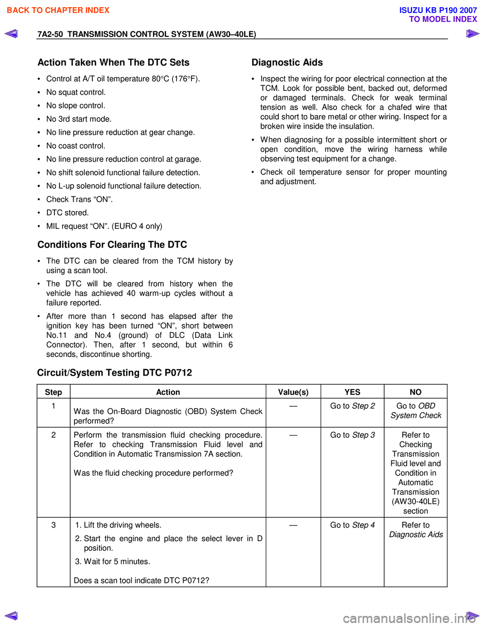
7A2-50 TRANSMISSION CONTROL SYSTEM (AW30–40LE)
Action Taken When The DTC Sets
• Control at A/T oil temperature 80 °C (176 °F).
• No squat control.
• No slope control.
• No 3rd start mode.
• No line pressure reduction at gear change.
• No coast control.
• No line pressure reduction control at garage.
• No shift solenoid functional failure detection.
• No L-up solenoid functional failure detection.
• Check Trans “ON”.
• DTC stored.
• MIL request “ON”. (EURO 4 only)
Conditions For Clearing The DTC
• The DTC can be cleared from the TCM history by
using a scan tool.
• The DTC will be cleared from history when the vehicle has achieved 40 warm-up cycles without a
failure reported.
•
After more than 1 second has elapsed after the
ignition key has been turned “ON”, short between
No.11 and No.4 (ground) of DLC (Data Link
Connector). Then, after 1 second, but within 6
seconds, discontinue shorting.
Diagnostic Aids
•
Inspect the wiring for poor electrical connection at the
TCM. Look for possible bent, backed out, deformed
or damaged terminals. Check for weak terminal
tension as well. Also check for a chafed wire that
could short to bare metal or other wiring. Inspect for a
broken wire inside the insulation.
• W hen diagnosing for a possible intermittent short o
r
open condition, move the wiring harness while
observing test equipment for a change.
• Check oil temperature sensor for proper mounting and adjustment.
Circuit/System Testing DTC P0712
Step Action Value(s) YES NO
1
W as the On-Board Diagnostic (OBD) System Check
performed? — Go to
Step 2 Go to OBD
System Check
2 Perform the transmission fluid checking procedure. Refer to checking Transmission Fluid level and
Condition in Automatic Transmission 7A section.
W as the fluid checking procedure performed? — Go to
Step 3 Refer to
Checking
Transmission
Fluid level and Condition in Automatic
Transmission
(AW 30-40LE) section
3 1. Lift the driving wheels.
2. Start the engine and place the select lever in D
position.
3. W ait for 5 minutes.
Does a scan tool indicate DTC P0712? — Go to
Step 4 Refer to
Diagnostic Aids
BACK TO CHAPTER INDEX
TO MODEL INDEX
ISUZU KB P190 2007
Page 4019 of 6020
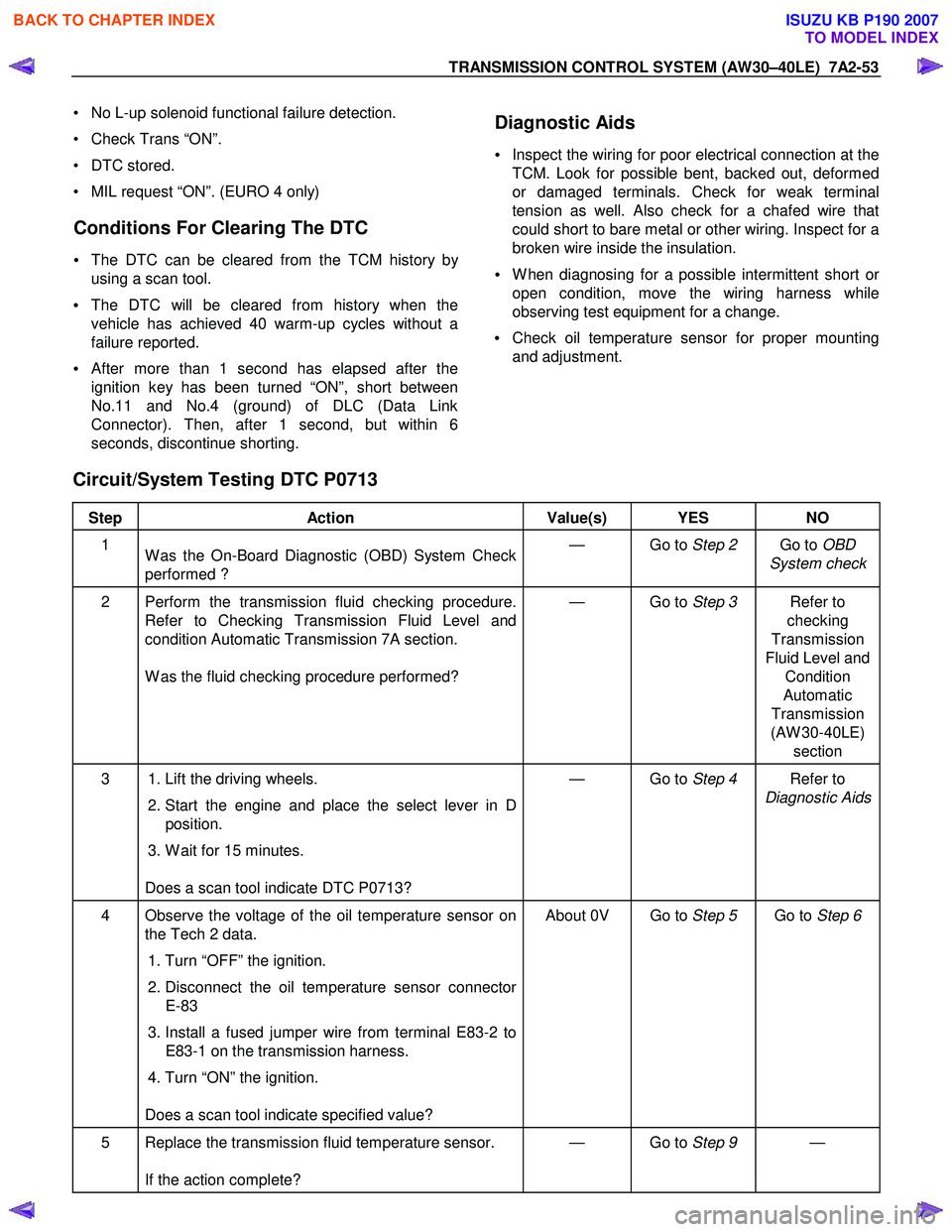
TRANSMISSION CONTROL SYSTEM (AW30–40LE) 7A2-53
• No L-up solenoid functional failure detection.
• Check Trans “ON”.
• DTC stored.
• MIL request “ON”. (EURO 4 only)
Conditions For Clearing The DTC
• The DTC can be cleared from the TCM history by
using a scan tool.
• The DTC will be cleared from history when the
vehicle has achieved 40 warm-up cycles without a
failure reported.
•
After more than 1 second has elapsed after the
ignition key has been turned “ON”, short between
No.11 and No.4 (ground) of DLC (Data Link
Connector). Then, after 1 second, but within 6
seconds, discontinue shorting.
Diagnostic Aids
•
Inspect the wiring for poor electrical connection at the
TCM. Look for possible bent, backed out, deformed
or damaged terminals. Check for weak terminal
tension as well. Also check for a chafed wire that
could short to bare metal or other wiring. Inspect for a
broken wire inside the insulation.
• W hen diagnosing for a possible intermittent short o
r
open condition, move the wiring harness while
observing test equipment for a change.
• Check oil temperature sensor for proper mounting
and adjustment.
Circuit/System Testing DTC P0713
Step Action Value(s) YES NO
1
W as the On-Board Diagnostic (OBD) System Check
performed ? — Go to
Step 2 Go to OBD
System check
2 Perform the transmission fluid checking procedure. Refer to Checking Transmission Fluid Level and
condition Automatic Transmission 7A section.
W as the fluid checking procedure performed? — Go to
Step 3 Refer to
checking
Transmission
Fluid Level and Condition
Automatic
Transmission
(AW 30-40LE) section
3 1. Lift the driving wheels.
2. Start the engine and place the select lever in D
position.
3. W ait for 15 minutes.
Does a scan tool indicate DTC P0713? — Go to
Step 4 Refer to
Diagnostic Aids
4 Observe the voltage of the oil temperature sensor on the Tech 2 data.
1. Turn “OFF” the ignition.
2. Disconnect the oil temperature sensor connector
E-83
3. Install a fused jumper wire from terminal E83-2 to E83-1 on the transmission harness.
4. Turn “ON” the ignition.
Does a scan tool indicate specified value? About 0V Go to
Step 5 Go to Step 6
5 Replace the transmission fluid temperature sensor.
If the action complete? — Go to
Step 9 —
BACK TO CHAPTER INDEX
TO MODEL INDEX
ISUZU KB P190 2007
Page 4022 of 6020
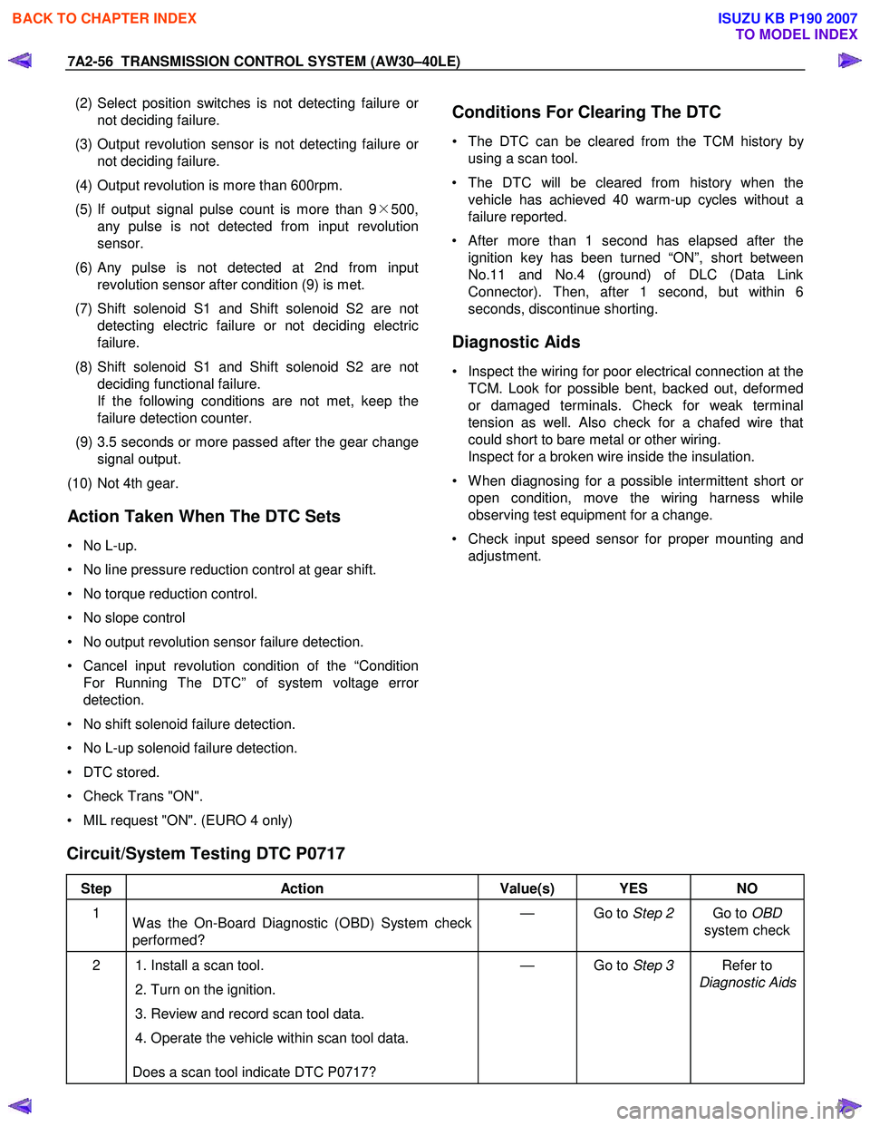
7A2-56 TRANSMISSION CONTROL SYSTEM (AW30–40LE)
(2) Select position switches is not detecting failure o
r
not deciding failure.
(3) Output revolution sensor is not detecting failure o
r
not deciding failure.
(4) Output revolution is more than 600rpm.
(5) If output signal pulse count is more than 9 ×500,
any pulse is not detected from input revolution
sensor.
(6)
Any pulse is not detected at 2nd from input
revolution sensor after condition (9) is met.
(7) Shift solenoid S1 and Shift solenoid S2 are not detecting electric failure or not deciding electric
failure.
(8) Shift solenoid S1 and Shift solenoid S2 are not deciding functional failure.
If the following conditions are not met, keep the
failure detection counter.
(9) 3.5 seconds or more passed after the gear change signal output.
(10) Not 4th gear.
Action Taken When The DTC Sets
• No L-up.
• No line pressure reduction control at gear shift.
• No torque reduction control.
• No slope control
• No output revolution sensor failure detection.
• Cancel input revolution condition of the “Condition For Running The DTC” of system voltage erro
r
detection.
• No shift solenoid failure detection.
• No L-up solenoid failure detection.
• DTC stored.
• Check Trans "ON".
• MIL request "ON". (EURO 4 only)
Conditions For Clearing The DTC
• The DTC can be cleared from the TCM history by
using a scan tool.
• The DTC will be cleared from history when the vehicle has achieved 40 warm-up cycles without a
failure reported.
•
After more than 1 second has elapsed after the
ignition key has been turned “ON”, short between
No.11 and No.4 (ground) of DLC (Data Link
Connector). Then, after 1 second, but within 6
seconds, discontinue shorting.
Diagnostic Aids
• Inspect the wiring for poor electrical connection at the TCM. Look for possible bent, backed out, deformed
or damaged terminals. Check for weak terminal
tension as well. Also check for a chafed wire that
could short to bare metal or other wiring.
Inspect for a broken wire inside the insulation.
• W hen diagnosing for a possible intermittent short o
r
open condition, move the wiring harness while
observing test equipment for a change.
• Check input speed sensor for proper mounting and adjustment.
Circuit/System Testing DTC P0717
Step Action Value(s) YES NO
1
W as the On-Board Diagnostic (OBD) System check
performed? — Go to
Step 2 Go to OBD
system check
2 1. Install a scan tool.
2. Turn on the ignition.
3. Review and record scan tool data.
4. Operate the vehicle within scan tool data.
Does a scan tool indicate DTC P0717? — Go to
Step 3 Refer to
Diagnostic Aids
BACK TO CHAPTER INDEX
TO MODEL INDEX
ISUZU KB P190 2007
Page 4026 of 6020
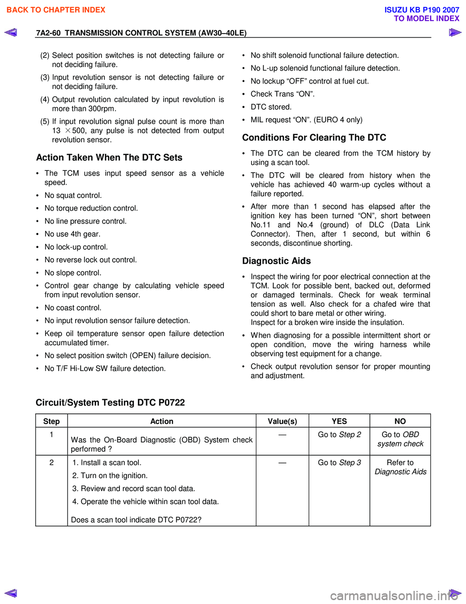
7A2-60 TRANSMISSION CONTROL SYSTEM (AW30–40LE)
(2) Select position switches is not detecting failure o
r
not deciding failure.
(3) Input revolution sensor is not detecting failure o
r
not deciding failure.
(4) Output revolution calculated by input revolution is more than 300rpm.
(5) If input revolution signal pulse count is more than 13 ×500, any pulse is not detected from output
revolution sensor.
Action Taken When The DTC Sets
• The TCM uses input speed sensor as a vehicle
speed.
• No squat control.
• No torque reduction control.
• No line pressure control.
• No use 4th gear.
• No lock-up control.
• No reverse lock out control.
• No slope control.
• Control gear change by calculating vehicle speed from input revolution sensor.
• No coast control.
• No input revolution sensor failure detection.
• Keep oil temperature sensor open failure detection accumulated timer.
• No select position switch (OPEN) failure decision.
• No T/F Hi-Low SW failure detection.
• No shift solenoid functional failure detection.
• No L-up solenoid functional failure detection.
• No lockup “OFF” control at fuel cut.
• Check Trans “ON”.
• DTC stored.
• MIL request “ON”. (EURO 4 only)
Conditions For Clearing The DTC
• The DTC can be cleared from the TCM history by
using a scan tool.
• The DTC will be cleared from history when the vehicle has achieved 40 warm-up cycles without a
failure reported.
•
After more than 1 second has elapsed after the
ignition key has been turned “ON”, short between
No.11 and No.4 (ground) of DLC (Data Link
Connector). Then, after 1 second, but within 6
seconds, discontinue shorting.
Diagnostic Aids
• Inspect the wiring for poor electrical connection at the
TCM. Look for possible bent, backed out, deformed
or damaged terminals. Check for weak terminal
tension as well. Also check for a chafed wire that
could short to bare metal or other wiring.
Inspect for a broken wire inside the insulation.
• W hen diagnosing for a possible intermittent short o
r
open condition, move the wiring harness while
observing test equipment for a change.
• Check output revolution sensor for proper mounting and adjustment.
Circuit/System Testing DTC P0722
Step Action Value(s) YES NO
1
W as the On-Board Diagnostic (OBD) System check
performed ? — Go to
Step 2 Go to OBD
system check
2 1. Install a scan tool.
2. Turn on the ignition.
3. Review and record scan tool data.
4. Operate the vehicle within scan tool data.
Does a scan tool indicate DTC P0722? — Go to
Step 3 Refer to
Diagnostic Aids
BACK TO CHAPTER INDEX
TO MODEL INDEX
ISUZU KB P190 2007