2007 ISUZU KB P190 key
[x] Cancel search: keyPage 3498 of 6020
Engine Management – V6 – Diagnostics Page 6C1-2–220
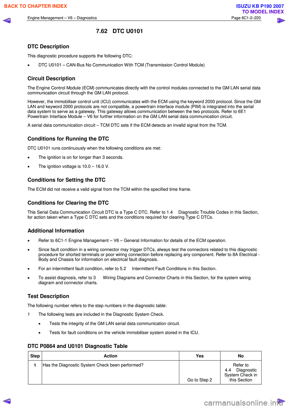
7.62 DTC U0101
DTC Description
This diagnostic procedure supports the following DTC:
• DTC U0101 – CAN-Bus No Communication W ith TCM (Transmission Control Module)
Circuit Description
The Engine Control Module (ECM) communicates directly with the control modules connected to the GM LAN serial data
communication circuit through the GM LAN protocol.
However, the immobiliser control unit (ICU) communicates with the ECM using the keyword 2000 protocol. Since the GM
LAN and keyword 2000 protocols are not compatible, a powertrain interface module (PIM) is integrated into the serial
data system to serve as a gateway. This gateway allows communication between the two protocols. Refer to 6E1
Powertrain Interface Module – V6 for further information on the GM LAN serial data communication circuit.
A serial data communication circuit – TCM DTC sets if the ECM detects an invalid signal from the TCM.
Conditions for Running the DTC
DTC U0101 runs continuously when the following conditions are met:
• The ignition is on for longer than 3 seconds.
• The ignition voltage is 10.0 – 16.0 V.
Conditions for Setting the DTC
The ECM did not receive a valid signal from the TCM within the specified time frame.
Conditions for Clearing the DTC
This Serial Data Communication Circuit DTC is a Type C DTC. Refer to 1.4 Diagnostic Trouble Codes in this Section,
for action taken when a Type C DTC sets and the conditions required for clearing Type C DTCs.
Additional Information
• Refer to 6C1-1 Engine Management – V6 – General Information for details of the ECM operation.
• Since fault condition in a wiring connector may trigger DTCs, always test the connectors related to this diagnostic
procedure for shorted terminals or poor wiring connection before replacing any component. Refer to 8A Electrical -
Body and Chassis for information on electrical fault diagnosis.
• For an intermittent fault condition, refer to 5.2 Intermittent Fault Conditions in this Section.
• To assist diagnosis, refer to 3 W iring Diagrams and Connector Charts in this Section, for the system wiring
diagram and connector charts.
Test Description
The following number refers to the step numbers in the diagnostic table:
1 The following tests are included in the Diagnostic System Check.
• Tests the integrity of the GM LAN serial data communication circuit.
• Tests for fault conditions on the vehicle immobiliser system stored in the ICU.
DTC P0864 and U0101 Diagnostic Table
Step Action Yes No
1 Has the Diagnostic System Check been performed?
Go to Step 2 Refer to
4.4 Diagnostic
System Check in this Section
BACK TO CHAPTER INDEX
TO MODEL INDEX
ISUZU KB P190 2007
Page 3499 of 6020
Engine Management – V6 – Diagnostics Page 6C1-2–221
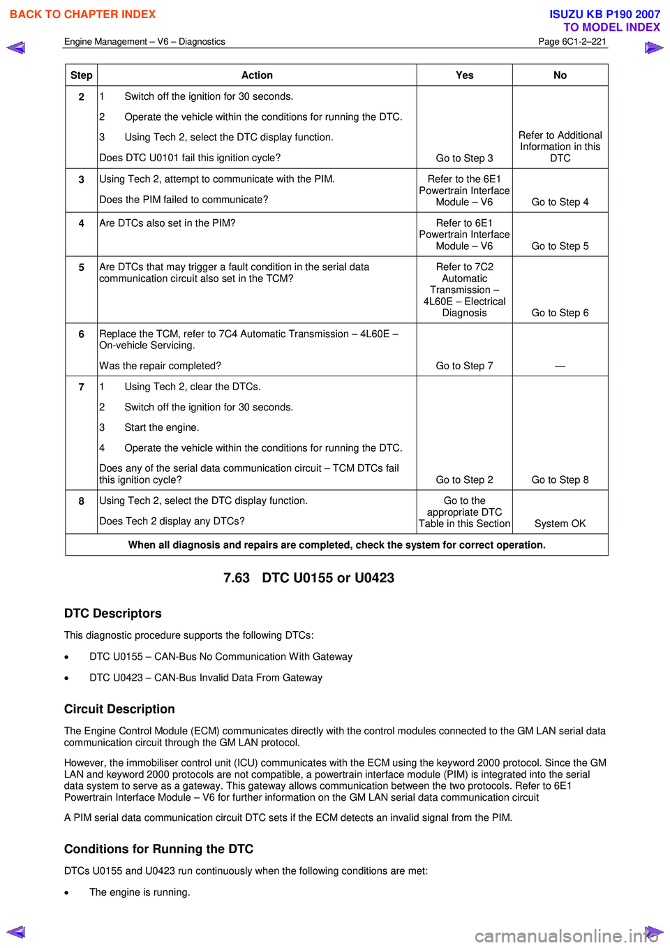
Step Action Yes No
2 1 Switch off the ignition for 30 seconds.
2 Operate the vehicle within the conditions for running the DTC.
3 Using Tech 2, select the DTC display function.
Does DTC U0101 fail this ignition cycle? Go to Step 3 Refer to Additional
Information in this DTC
3 Using Tech 2, attempt to communicate with the PIM.
Does the PIM failed to communicate? Refer to the 6E1
Powertrain Interface Module – V6 Go to Step 4
4 Are DTCs also set in the PIM? Refer to 6E1
Powertrain Interface Module – V6 Go to Step 5
5 Are DTCs that may trigger a fault condition in the serial data
communication circuit also set in the TCM? Refer to 7C2
Automatic
Transmission –
4L60E – Electrical Diagnosis Go to Step 6
6 Replace the TCM, refer to 7C4 Automatic Transmission – 4L60E –
On-vehicle Servicing.
W as the repair completed? Go to Step 7 —
7 1 Using Tech 2, clear the DTCs.
2 Switch off the ignition for 30 seconds.
3 Start the engine.
4 Operate the vehicle within the conditions for running the DTC.
Does any of the serial data communication circuit – TCM DTCs fail
this ignition cycle? Go to Step 2 Go to Step 8
8 Using Tech 2, select the DTC display function.
Does Tech 2 display any DTCs? Go to the
appropriate DTC
Table in this Section System OK
When all diagnosis and repairs are completed, check the system for correct operation.
7.63 DTC U0155 or U0423
DTC Descriptors
This diagnostic procedure supports the following DTCs:
• DTC U0155 – CAN-Bus No Communication W ith Gateway
• DTC U0423 – CAN-Bus Invalid Data From Gateway
Circuit Description
The Engine Control Module (ECM) communicates directly with the control modules connected to the GM LAN serial data
communication circuit through the GM LAN protocol.
However, the immobiliser control unit (ICU) communicates with the ECM using the keyword 2000 protocol. Since the GM
LAN and keyword 2000 protocols are not compatible, a powertrain interface module (PIM) is integrated into the serial
data system to serve as a gateway. This gateway allows communication between the two protocols. Refer to 6E1
Powertrain Interface Module – V6 for further information on the GM LAN serial data communication circuit
A PIM serial data communication circuit DTC sets if the ECM detects an invalid signal from the PIM.
Conditions for Running the DTC
DTCs U0155 and U0423 run continuously when the following conditions are met:
• The engine is running.
BACK TO CHAPTER INDEX
TO MODEL INDEX
ISUZU KB P190 2007
Page 3523 of 6020
Engine Management – V6 – Diagnostics Page 6C1-2–245
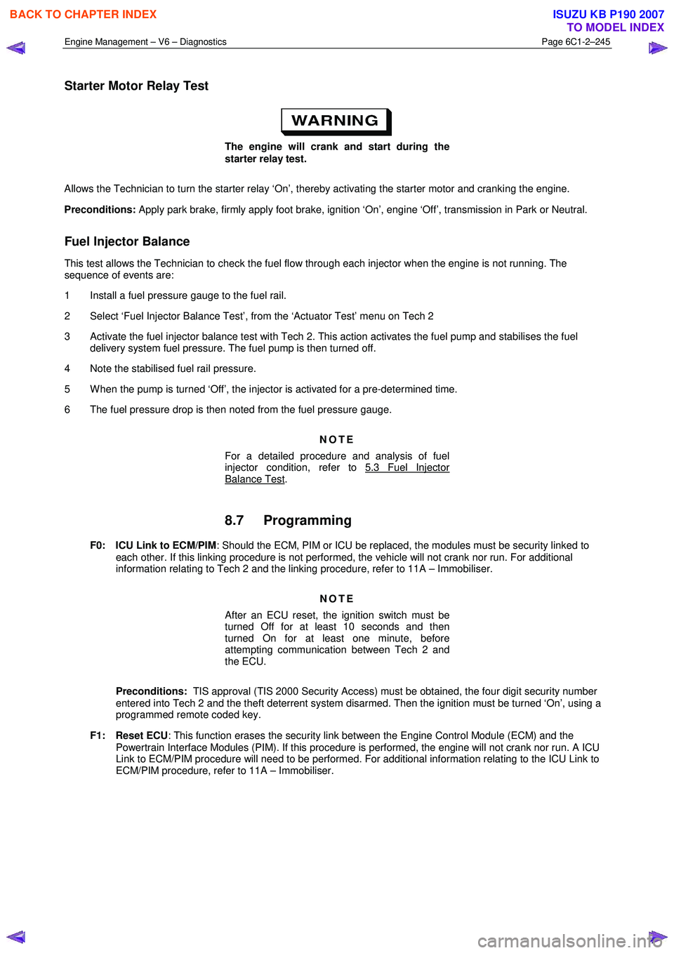
Starter Motor Relay Test
The engine will crank and start during the
starter relay test.
Allows the Technician to turn the starter relay ‘On’, thereby activating the starter motor and cranking the engine.
Preconditions: Apply park brake, firmly apply foot brake, ignition ‘On’, engine ‘Off’, transmission in Park or Neutral.
Fuel Injector Balance
This test allows the Technician to check the fuel flow through each injector when the engine is not running. The
sequence of events are:
1 Install a fuel pressure gauge to the fuel rail.
2 Select ‘Fuel Injector Balance Test’, from the ‘Actuator Test’ menu on Tech 2
3 Activate the fuel injector balance test with Tech 2. This action activates the fuel pump and stabilises the fuel delivery system fuel pressure. The fuel pump is then turned off.
4 Note the stabilised fuel rail pressure.
5 W hen the pump is turned ‘Off’, the injector is activated for a pre-determined time.
6 The fuel pressure drop is then noted from the fuel pressure gauge.
NOTE
For a detailed procedure and analysis of fuel
injector condition, refer to 5.3 Fuel Injector
Balance Test.
8.7 Programming
F0: ICU Link to ECM/PIM : Should the ECM, PIM or ICU be replaced, the modules must be security linked to
each other. If this linking procedure is not performed, the vehicle will not crank nor run. For additional
information relating to Tech 2 and the linking procedure, refer to 11A – Immobiliser.
NOTE
After an ECU reset, the ignition switch must be
turned Off for at least 10 seconds and then
turned On for at least one minute, before
attempting communication between Tech 2 and
the ECU.
Preconditions: TIS approval (TIS 2000 Security Access) must be obtained, the four digit security number
entered into Tech 2 and the theft deterrent system disarmed. Then the ignition must be turned ‘On’, using a
programmed remote coded key.
F1: Reset ECU : This function erases the security link between the Engine Control Module (ECM) and the
Powertrain Interface Modules (PIM). If this procedure is performed, the engine will not crank nor run. A ICU
Link to ECM/PIM procedure will need to be performed. For additional information relating to the ICU Link to
ECM/PIM procedure, refer to 11A – Immobiliser.
BACK TO CHAPTER INDEX
TO MODEL INDEX
ISUZU KB P190 2007
Page 3524 of 6020
Engine Management – V6 – Diagnostics Page 6C1-2–246
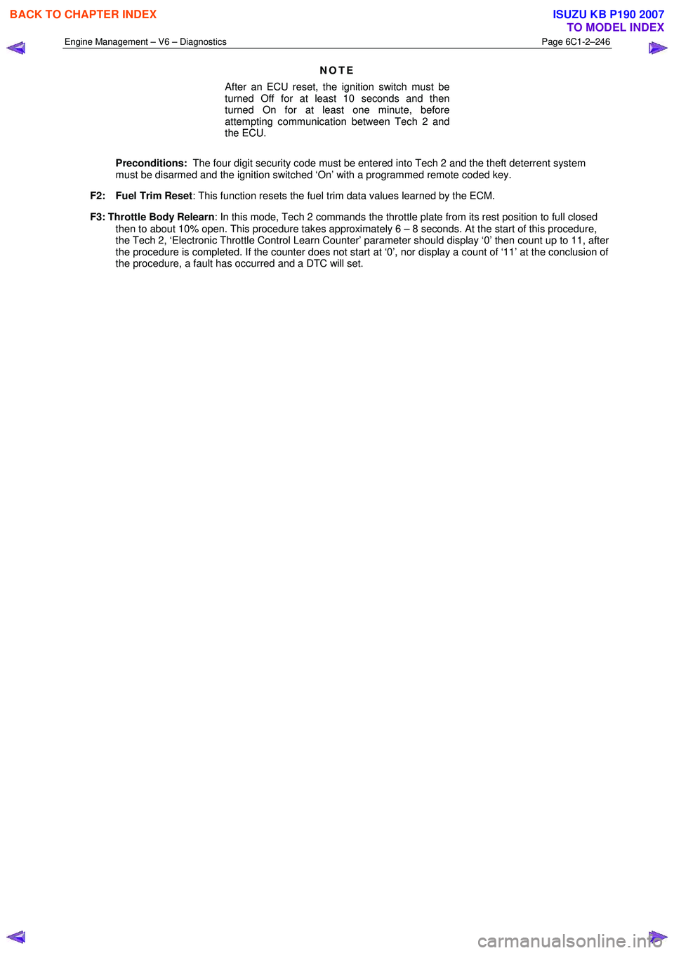
NOTE
After an ECU reset, the ignition switch must be
turned Off for at least 10 seconds and then
turned On for at least one minute, before
attempting communication between Tech 2 and
the ECU.
Preconditions: The four digit security code must be entered into Tech 2 and the theft deterrent system
must be disarmed and the ignition switched ‘On’ with a programmed remote coded key.
F2: Fuel Trim Reset : This function resets the fuel trim data values learned by the ECM.
F3: Throttle Body Relearn : In this mode, Tech 2 commands the throttle plate from its rest position to full closed
then to about 10% open. This procedure takes approximately 6 – 8 seconds. At the start of this procedure,
the Tech 2, ‘Electronic Throttle Control Learn Counter’ parameter should display ‘0’ then count up to 11, after
the procedure is completed. If the counter does not start at ‘0’, nor display a count of ‘11’ at the conclusion of
the procedure, a fault has occurred and a DTC will set.
BACK TO CHAPTER INDEX
TO MODEL INDEX
ISUZU KB P190 2007
Page 3545 of 6020
Engine Management – V6 – Service Operations Page 6C1-3–21
NOTE
When Tech 2 requests programming approval,
obtain TIS approval.
3 W hen Tech 2 displays Enter Security Code, enter the security code, press the Enter key and then the Okay soft
key.
The engine will not start after the ECM has
been reset.
4 W hen Tech 2 displays Do you really want to Reset? , press the Reset soft key.
5 W hen Tech 2 displays Stop Engine - Turn Off Ignition , turn the ignition off and press the Confirm soft key.
6 W hen Tech 2 displays Turn Ignition On, turn the ignition on and press the Confirm soft key.
7 W hen Tech 2 displays Reset Completed Successfully , press the Confirm soft key to return to the Tech 2
Programming screen.
2.8 Engine Control Module Bracket Assembly
Remove
1 Remove the engine control module (ECM), refer to 2.7 Engine Control Module.
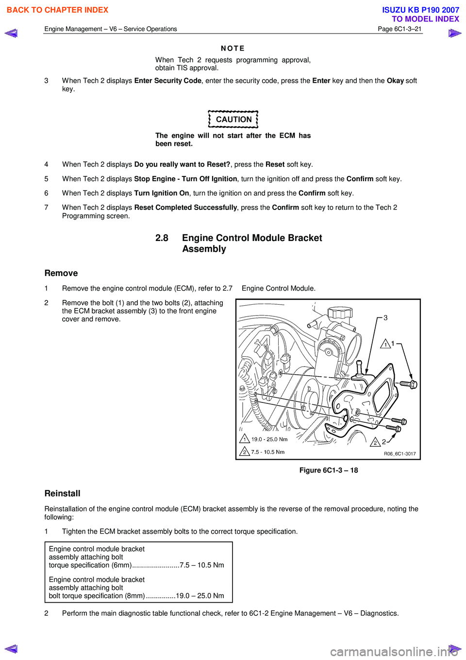
2 Remove the bolt (1) and the two bolts (2), attaching the ECM bracket assembly (3) to the front engine
cover and remove.
Figure 6C1-3 – 18
Reinstall
Reinstallation of the engine control module (ECM) bracket assembly is the reverse of the removal procedure, noting the
following:
1 Tighten the ECM bracket assembly bolts to the correct torque specification.
Engine control module bracket
assembly attaching bolt
torque specification (6mm)........................7.5 – 10.5 Nm
Engine control module bracket
assembly attaching bolt
bolt torque specification (8mm) ...............19.0 – 25.0 Nm
2 Perform the main diagnostic table functional check, refer to 6C1-2 Engine Management – V6 – Diagnostics.
BACK TO CHAPTER INDEX
TO MODEL INDEX
ISUZU KB P190 2007
Page 3612 of 6020
Starting System – V6 Page 6D1-2–4
• Clarify a procedure,
• Present additional information for accomplishing a procedure,
• Give insight into the reasons for performing a procedure in the recommended manner, and / or
Present information that gives the technician the benefit of past experience in accomplishing a procedure with greater
ease.
1.2 Components
Starting System Components
The main components of the starting system are:
• battery,
• wiring,
• ignition switch,
• theft deterrent engine crank inhibitor (a function of the theft deterrent system),
• park / neutral and back-up switch (on vehicles with 4 speed automatic transmission),
• engine control module (ECM),
• start relay,
• solenoid switch, and
• starter motor.
Starter Motor and Solenoid Switch Components
Solenoid Switch
The solenoid switch is used to activate the DC motor and has two windings; the pull-in winding and the hold-in winding.
The pull-in winding has heavier wire and is grounded through the DC motor winding and brushes. The hold-in winding is
grounded through the solenoid casing.
Planetary Drive Train
The planetary drive train consists of an internally toothed ring gear and three planetary gear wheels, which rotate on
sleeve bearings on the planetary drive shaft. The ring gear is keyed into the drive-end housing and is made from
high-grade polyamide with mineral additives.
W hen the starter motor operates, the armature turns the planetary gears inside the fixed planetary ring gear. This drives
the planetary shaft at a reduced speed ratio which turns the drive assembly. A fork lever in the drive-end housing forces
the drive assembly forward to engage with the flexplate / flywheel ring gear on the engine and transmit cranking torque.
An internal clutch allows the drive assembly pinion gear to rotate freely when the engine starts. This prevents the
armature from being driven at excessive speed by the engine.
Armature
The armature shaft is supported at each end by oil absorbent, sintered metal bushes; one in the commutator end shield
and one in the planetary drive shaft. The front end of the armature has a gear profile. This meshes with the three
planetary gear wheels. These in turn, mesh with the internal teeth of the ring gear.
Brushes
A brush plate supports four commutator brushes. This plate is fixed to the commutator end shield with two retaining
screws. Two negative brushes are grounded to the pole housing. The two positive brushes are insulated from the pole
housing and connected to the solenoid switch M terminal, refer to Figure 6D1-2 – 1.
BACK TO CHAPTER INDEX
TO MODEL INDEX
ISUZU KB P190 2007
Page 3667 of 6020
Powertrain Interface Module – V6 Page 6E1–6
1 General Information
A powertrain interface module (PIM) is fitted that incorporates the following functionality:
• Communication protocol between the engine control module (ECM) and transmission control module (TCM) is
General Motors Local Area Network (GM LAN).
• Communication protocol between the PIM and immobiliser control unit is keyword 2000.
• ECM to PIM and PIM to immobiliser control unit (ICU) authentication for vehicle security.
• The following switches, where fitted, input directly into the PIM:
• Automatic transmission power mode switch.
• Automatic transmission 3
rd gear start switch.
• Cruise control switch.
1.1 General Description
Serial Data Communication
The various electronic control modules communicate with each other through the serial data bus. The ECM and TCM
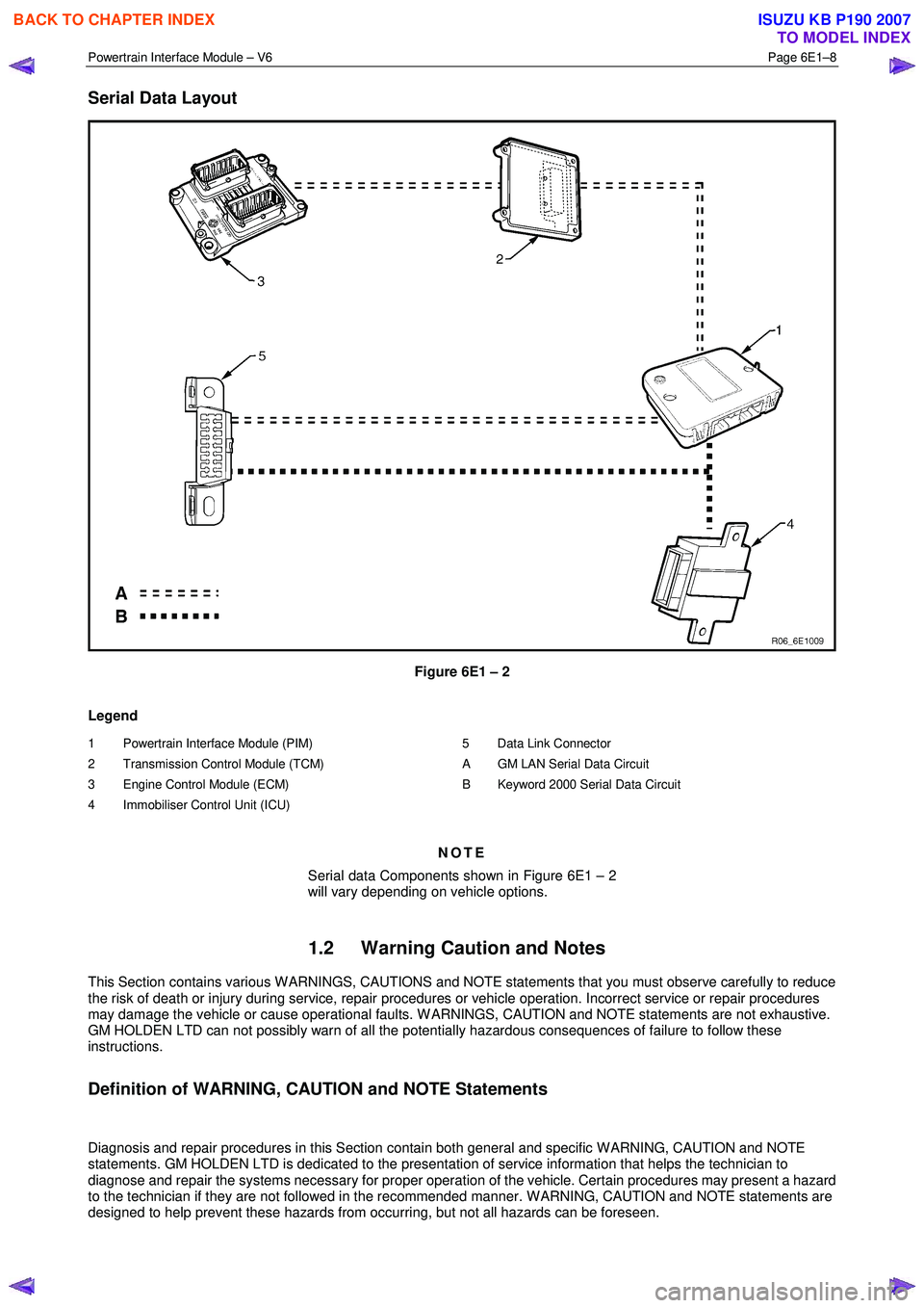
communicate on the serial data bus using the GM LAN communication protocol. Figure 6E1 – 2 shows the serial data
layout.
NOTE
Serial data components shown in Figure 6E1 – 2
will vary depending on vehicle options.
Bus
A bus is a physical circuit or circuits which provides a communication path between two or more control modules.
GM LAN Serial Data Bus
The GM LAN bus is a two wire circuit (1), refer to Figure 6E1 – 1. The GM LAN bus circuits are terminated with cut-off
resistors (2) which are located inside the two control modules at either end of the bus circuit. The purpose of these cut-off
resistors is to prevent data from returning as an echo after reaching the end of the GM LAN bus circuit.
NOTE
• For illustration purposes, the cut-off resistors
are shown outside of the control modules.
• The two control modules with the cut-off
resistors are the PIM and the ECM.
BACK TO CHAPTER INDEX
TO MODEL INDEX
ISUZU KB P190 2007
Page 3669 of 6020
Powertrain Interface Module – V6 Page 6E1–8
Serial Data Layout
Figure 6E1 – 2
Legend
1 Powertrain Interface Module (PIM)
2 Transmission Control Module (TCM)
3 Engine Control Module (ECM)
4 Immobiliser Control Unit (ICU)
5 Data Link Connector
A GM LAN Serial Data Circuit
B Keyword 2000 Serial Data Circuit
NOTE
Serial data Components shown in Figure 6E1 – 2
will vary depending on vehicle options.
1.2 Warning Caution and Notes
This Section contains various W ARNINGS, CAUTIONS and NOTE statements that you must observe carefully to reduce
the risk of death or injury during service, repair procedures or vehicle operation. Incorrect service or repair procedures
may damage the vehicle or cause operational faults. W ARNINGS, CAUTION and NOTE statements are not exhaustive.
GM HOLDEN LTD can not possibly warn of all the potentially hazardous consequences of failure to follow these
instructions.
Definition of WARNING, CAUTION and NOTE Statements
Diagnosis and repair procedures in this Section contain both general and specific W ARNING, CAUTION and NOTE
statements. GM HOLDEN LTD is dedicated to the presentation of service information that helps the technician to
diagnose and repair the systems necessary for proper operation of the vehicle. Certain procedures may present a hazard
to the technician if they are not followed in the recommended manner. W ARNING, CAUTION and NOTE statements are
designed to help prevent these hazards from occurring, but not all hazards can be foreseen.
BACK TO CHAPTER INDEX
TO MODEL INDEX
ISUZU KB P190 2007