2007 ISUZU KB P190 key
[x] Cancel search: keyPage 3132 of 6020
Engine Mechanical – V6 Page 6A1–355
Page 6A1–355
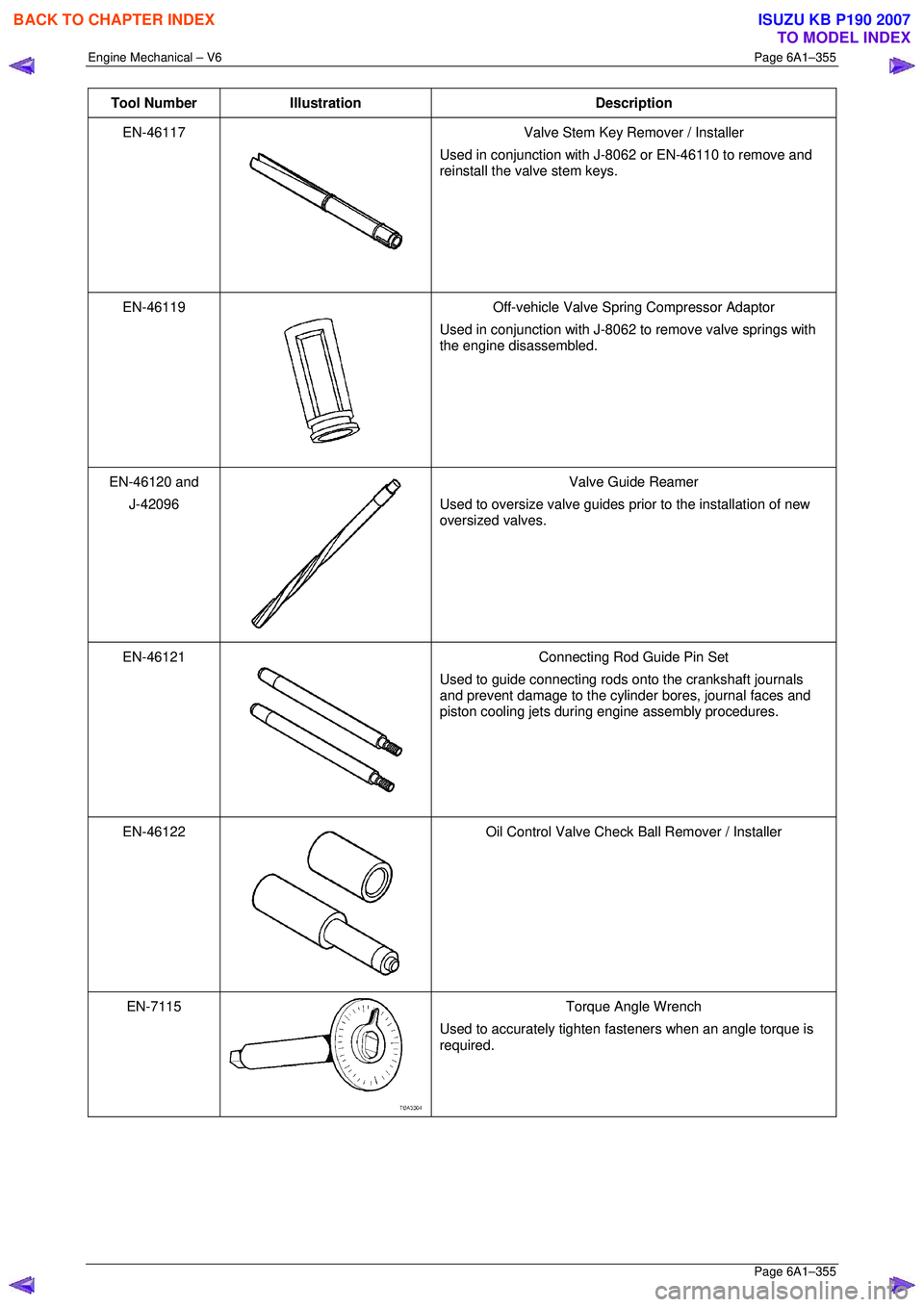
Tool Number Illustration Description
EN-46117
Valve Stem Key Remover / Installer
Used in conjunction with J-8062 or EN-46110 to remove and
reinstall the valve stem keys.
EN-46119
Off-vehicle Valve Spring Compressor Adaptor
Used in conjunction with J-8062 to remove valve springs with
the engine disassembled.
EN-46120 and
J-42096
Valve Guide Reamer
Used to oversize valve guides prior to the installation of new
oversized valves.
EN-46121
Connecting Rod Guide Pin Set
Used to guide connecting rods onto the crankshaft journals
and prevent damage to the cylinder bores, journal faces and
piston cooling jets during engine assembly procedures.
EN-46122
Oil Control Valve Check Ball Remover / Installer
EN-7115
Torque Angle Wrench
Used to accurately tighten fasteners when an angle torque is
required.
BACK TO CHAPTER INDEX
TO MODEL INDEX
ISUZU KB P190 2007
Page 3215 of 6020

Fuel System – V6 Page 6C – 13
4 Service Operations
4.1 Fuel Lines And Quick Connect Fittings
Description
The fuel line connector fittings contain the following
components:
1 O-rings
2 Fuel line port
3 Connector
4 Plastic fuel line tube
Figure 6C – 8
Leak Test and Inspection
1. Turn the ignition key to the ON position and ensure the fuel pump runs for a short time by listening for the pump start up sound. The fuel pressure will increase when the fuel pump is actuated.
2 Perform a preliminary check of the system by inspecting the system for any leaks around the connections and fittings.
3 Perform steps 1 and 2 several times.
4 If the preliminary check of the system produces no leaks, start the engine and check the system again for any sign of leaks around the connections and lines.
Ensure all service precautions have been
observed prior to removing any connector
fittings.
BACK TO CHAPTER INDEX
TO MODEL INDEX
ISUZU KB P190 2007
Page 3242 of 6020
Fuel System – V6 Page 6C – 40
7 Special Tools
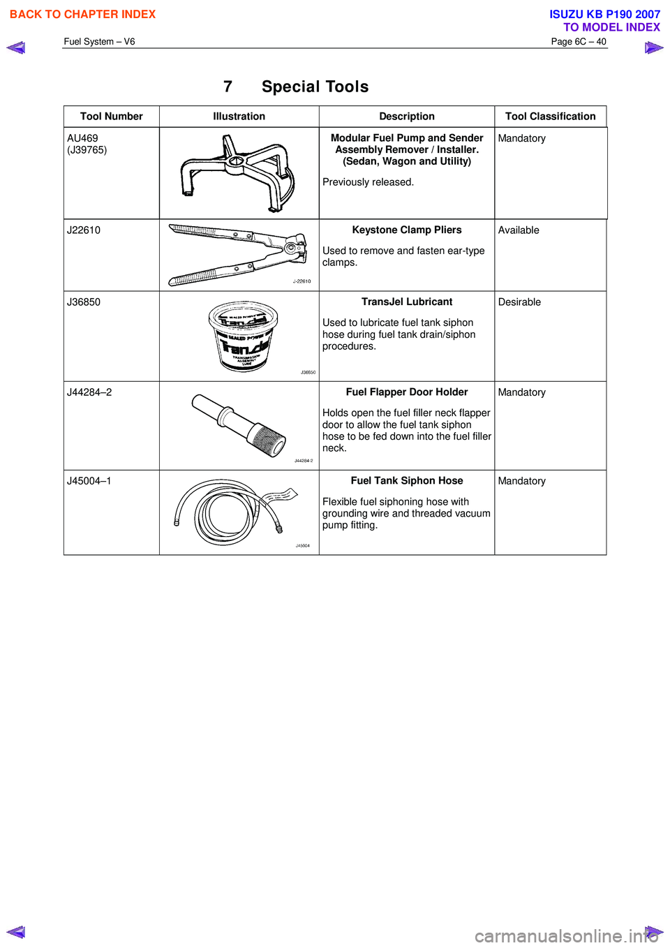
Tool Number Illustration Description Tool Classification
AU469
(J39765)
Modular Fuel Pump and Sender
Assembly Remover / Installer.
(Sedan, Wagon and Utility)
Previously released. Mandatory
J22610 Keystone Clamp Pliers
Used to remove and fasten ear-type
clamps. Available
J36850 TransJel Lubricant
Used to lubricate fuel tank siphon
hose during fuel tank drain/siphon
procedures. Desirable
J44284–2 Fuel Flapper Door Holder
Holds open the fuel filler neck flapper
door to allow the fuel tank siphon
hose to be fed down into the fuel filler
neck. Mandatory
J45004–1 Fuel Tank Siphon Hose
Flexible fuel siphoning hose with
grounding wire and threaded vacuum
pump fitting. Mandatory
BACK TO CHAPTER INDEX
TO MODEL INDEX
ISUZU KB P190 2007
Page 3259 of 6020
Engine Management – V6 – General Information Page 6C1-1–17
3.9 Serial Data Communication System
The engine control module (ECM) communicates directly with the following control units using the General Motors local
area network (GM LAN) serial data communication protocol:
• Transmission control module (TCM) (if fitted)
• Powertrain interface module (PIM)
The immobiliser control unit (ICU) communicates directly with the PIM using Keyword 2000 serial data communication
protocol. Refer to 11A Immobiliser for further information
As the GM LAN serial data communication protocol is not compatible with the Keyword 2000 serial data communication
protocol, a powertrain interface module (PIM) is integrated to the serial data communication system to perform the
following tasks (Refer to 6E1 Powertrain Interface Module – V6):
• Translate the GM LAN serial data transmitted by the ECM into a Keyword 2000 serial data that can be received
and recognised by the ICU.
• Translate the cruise control switch, automatic transmission power mode switch and 3
rd start switch signal into a GM
LAN serial data that can be received and recognised by the ECM.
3.10 Self Diagnostics System
The ECM constantly performs self-diagnostic tests on the engine management system. W hen the ECM detects a
malfunction, it also stores a diagnostic trouble code (DTC). A stored DTC will identify the problem area(s) and is
designed to assist the technician in rectifying the fault. In addition, DTCs are classified as either Current or History DTC.
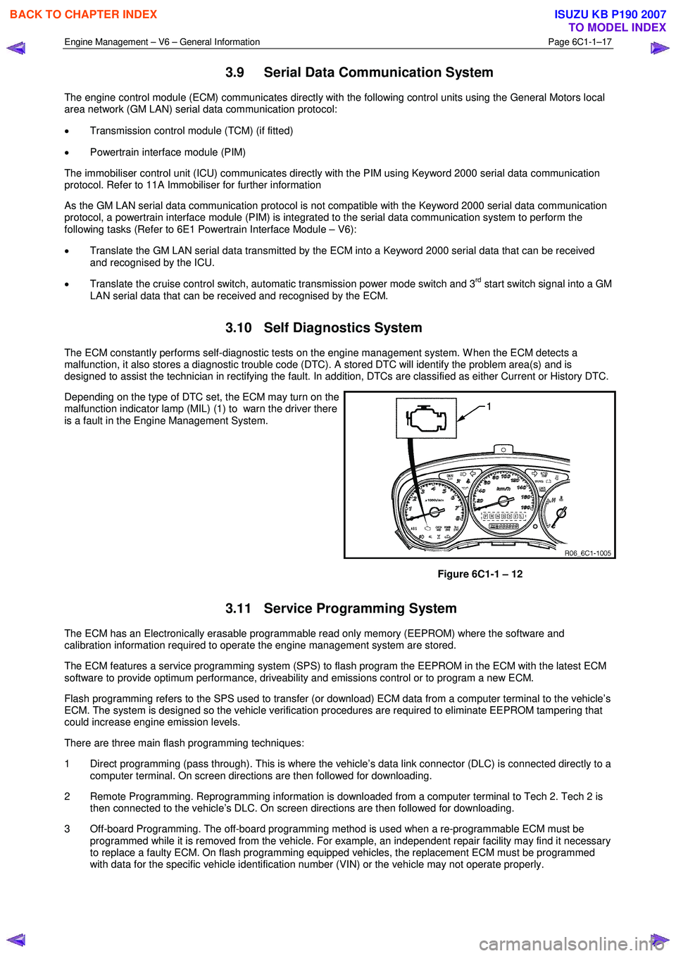
Depending on the type of DTC set, the ECM may turn on the
malfunction indicator lamp (MIL) (1) to warn the driver there
is a fault in the Engine Management System.
Figure 6C1-1 – 12
3.11 Service Programming System
The ECM has an Electronically erasable programmable read only memory (EEPROM) where the software and
calibration information required to operate the engine management system are stored.
The ECM features a service programming system (SPS) to flash program the EEPROM in the ECM with the latest ECM
software to provide optimum performance, driveability and emissions control or to program a new ECM.
Flash programming refers to the SPS used to transfer (or download) ECM data from a computer terminal to the vehicle’s
ECM. The system is designed so the vehicle verification procedures are required to eliminate EEPROM tampering that
could increase engine emission levels.
There are three main flash programming techniques:
1 Direct programming (pass through). This is where the vehicle’s data link connector (DLC) is connected directly to a computer terminal. On screen directions are then followed for downloading.
2 Remote Programming. Reprogramming information is downloaded from a computer terminal to Tech 2. Tech 2 is then connected to the vehicle’s DLC. On screen directions are then followed for downloading.
3 Off-board Programming. The off-board programming method is used when a re-programmable ECM must be programmed while it is removed from the vehicle. For example, an independent repair facility may find it necessary
to replace a faulty ECM. On flash programming equipped vehicles, the replacement ECM must be programmed
with data for the specific vehicle identification number (VIN) or the vehicle may not operate properly.
BACK TO CHAPTER INDEX
TO MODEL INDEX
ISUZU KB P190 2007
Page 3325 of 6020
Engine Management – V6 – Diagnostics Page 6C1-2–47
6.7 Throttle Body Relearn
A throttle body relearn procedure is performed in one of two ways:
• Engine Control Module initiated throttle body relearn, or
• Tech 2 initiated throttle body relearn.
Engine Control Module Throttle Body Relearn
The engine control module (ECM) will automatically perform a throttle body relearn procedure if either of the following
conditions exist:
• The battery has been disconnected, or
• The ignition switch is in the ON position for greater than 29 seconds, and the following conditions are met:
− Engine speed is less than 40 rpm,
− Vehicle speed is 0 km/h,
− Engine coolant temperature is 5 – 60°C,
− Intake air temperature is 5 – 60°C,
− Accelerator pedal position sensor angle is less than 14.9%, and
− Ignition voltage is greater than 10 V.
Tech 2 Throttle Body Relearn
To perform a throttle body relearn using Tech 2, complete the following procedure:
NOTE
Tech 2 will not initiate a throttle body relearn if
the engine is running.
1 Connect Tech 2 to the data link connector (DLC) and turn the ignition on.
2 On Tech 2 select Engine / Programming / Throttle Body Relearn.
3 W hen Tech 2 displays ‘Do you really want to Reset?’, press the ‘Yes’ soft key.
4 W hen Tech 2 displays ‘Programming Completed’, and the electronic throttle control value displayed by Tech 2 is ‘11’, press the ‘Confirm’ soft key to return to the Tech 2 Programming screen.
5 The throttle body relearn is now complete.
6.8 Electronic Ignition (EI) System Diagnosis
Circuit Description
The engine control module (ECM) controls the ignition coils by pulsing the ignition control (IC) circuits, which triggers an
ignition coil and fires the spark plug. The ECM controls the sequencing and the timing of each ignition coil. The ignition
system consist of the following components:
• The six ignition coils
• The crankshaft position (CKP) sensor
• The four camshaft position (CMP) sensors
• The ECM
The ignition coils use the following circuits:
• An IC circuit
• An ignition 1 voltage circuit
• Two ground circuits
BACK TO CHAPTER INDEX
TO MODEL INDEX
ISUZU KB P190 2007
Page 3333 of 6020
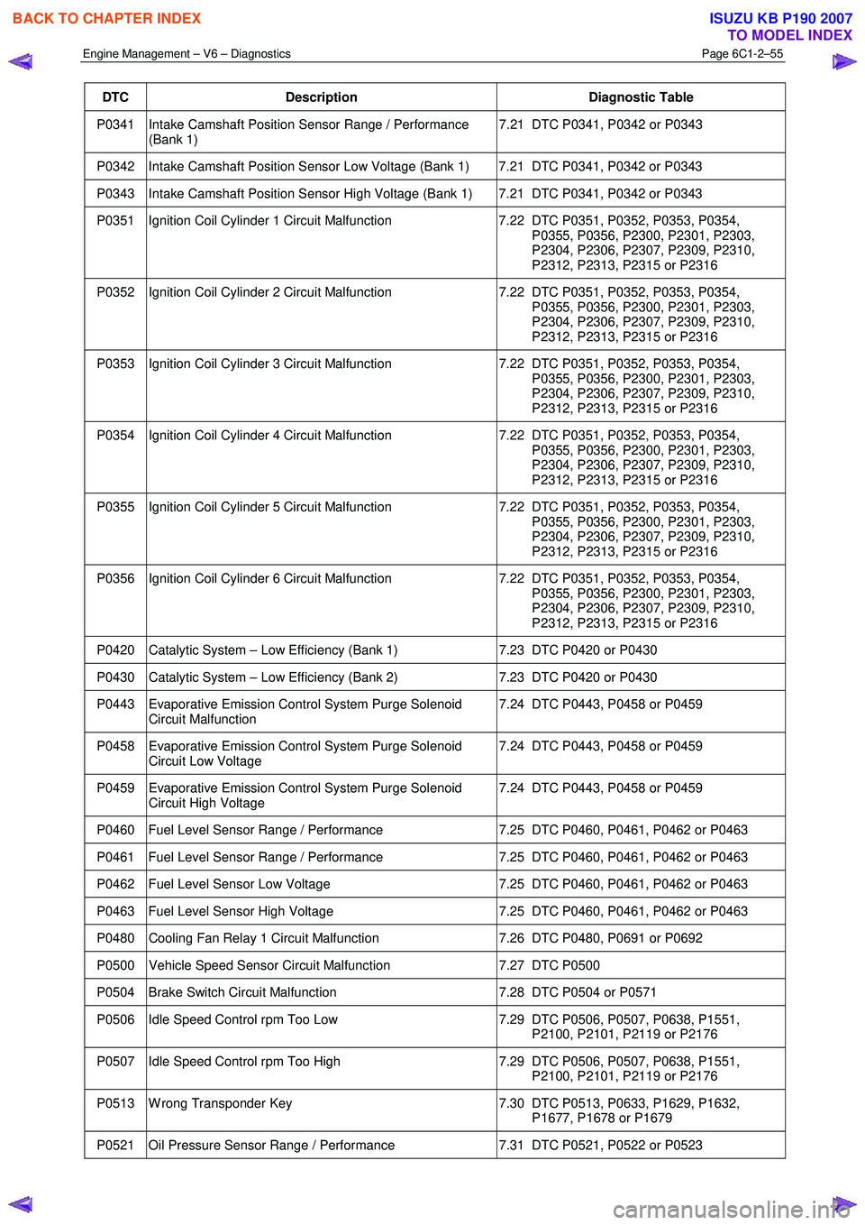
Engine Management – V6 – Diagnostics Page 6C1-2–55
DTC Description Diagnostic Table
P0341 Intake Camshaft Position Sensor Range / Performance
(Bank 1) 7.21 DTC P0341, P0342 or P0343
P0342 Intake Camshaft Position Sensor Low Voltage (Bank 1) 7.21 DTC P0341, P0342 or P0343
P0343 Intake Camshaft Position Sensor High Voltage (Bank 1) 7.21 DTC P0341, P0342 or P0343
P0351 Ignition Coil Cylinder 1 Circuit Malfunction
7.22 DTC P0351, P0352, P0353, P0354,
P0355, P0356, P2300, P2301, P2303,
P2304, P2306, P2307, P2309, P2310,
P2312, P2313, P2315 or P2316
P0352 Ignition Coil Cylinder 2 Circuit Malfunction 7.22 DTC P0351, P0352, P0353, P0354,
P0355, P0356, P2300, P2301, P2303,
P2304, P2306, P2307, P2309, P2310,
P2312, P2313, P2315 or P2316
P0353 Ignition Coil Cylinder 3 Circuit Malfunction 7.22 DTC P0351, P0352, P0353, P0354,
P0355, P0356, P2300, P2301, P2303,
P2304, P2306, P2307, P2309, P2310,
P2312, P2313, P2315 or P2316
P0354 Ignition Coil Cylinder 4 Circuit Malfunction 7.22 DTC P0351, P0352, P0353, P0354,
P0355, P0356, P2300, P2301, P2303,
P2304, P2306, P2307, P2309, P2310,
P2312, P2313, P2315 or P2316
P0355 Ignition Coil Cylinder 5 Circuit Malfunction 7.22 DTC P0351, P0352, P0353, P0354,
P0355, P0356, P2300, P2301, P2303,
P2304, P2306, P2307, P2309, P2310,
P2312, P2313, P2315 or P2316
P0356 Ignition Coil Cylinder 6 Circuit Malfunction 7.22 DTC P0351, P0352, P0353, P0354,
P0355, P0356, P2300, P2301, P2303,
P2304, P2306, P2307, P2309, P2310,
P2312, P2313, P2315 or P2316
P0420 Catalytic System – Low Efficiency (Bank 1) 7.23 DTC P0420 or P0430
P0430 Catalytic System – Low Efficiency (Bank 2) 7.23 DTC P0420 or P0430
P0443 Evaporative Emission Control System Purge Solenoid
Circuit Malfunction 7.24 DTC P0443, P0458 or P0459
P0458 Evaporative Emission Control System Purge Solenoid
Circuit Low Voltage 7.24 DTC P0443, P0458 or P0459
P0459 Evaporative Emission Control System Purge Solenoid
Circuit High Voltage 7.24 DTC P0443, P0458 or P0459
P0460 Fuel Level Sensor Range / Performance
7.25 DTC P0460, P0461, P0462 or P0463
P0461 Fuel Level Sensor Range / Performance 7.25 DTC P0460, P0461, P0462 or P0463
P0462 Fuel Level Sensor Low Voltage 7.25 DTC P0460, P0461, P0462 or P0463
P0463 Fuel Level Sensor High Voltage 7.25 DTC P0460, P0461, P0462 or P0463
P0480 Cooling Fan Relay 1 Circuit Malfunction 7.26 DTC P0480, P0691 or P0692
P0500 Vehicle Speed Sensor Circuit Malfunction 7.27 DTC P0500
P0504 Brake Switch Circuit Malfunction 7.28 DTC P0504 or P0571
P0506 Idle Speed Control rpm Too Low 7.29 DTC P0506, P0507, P0638, P1551,
P2100, P2101, P2119 or P2176
P0507 Idle Speed Control rpm Too High 7.29 DTC P0506, P0507, P0638, P1551,
P2100, P2101, P2119 or P2176
P0513 W rong Transponder Key 7.30 DTC P0513, P0633, P1629, P1632,
P1677, P1678 or P1679
P0521 Oil Pressure Sensor Range / Performance 7.31 DTC P0521, P0522 or P0523
BACK TO CHAPTER INDEX
TO MODEL INDEX
ISUZU KB P190 2007
Page 3417 of 6020
Engine Management – V6 – Diagnostics Page 6C1-2–139
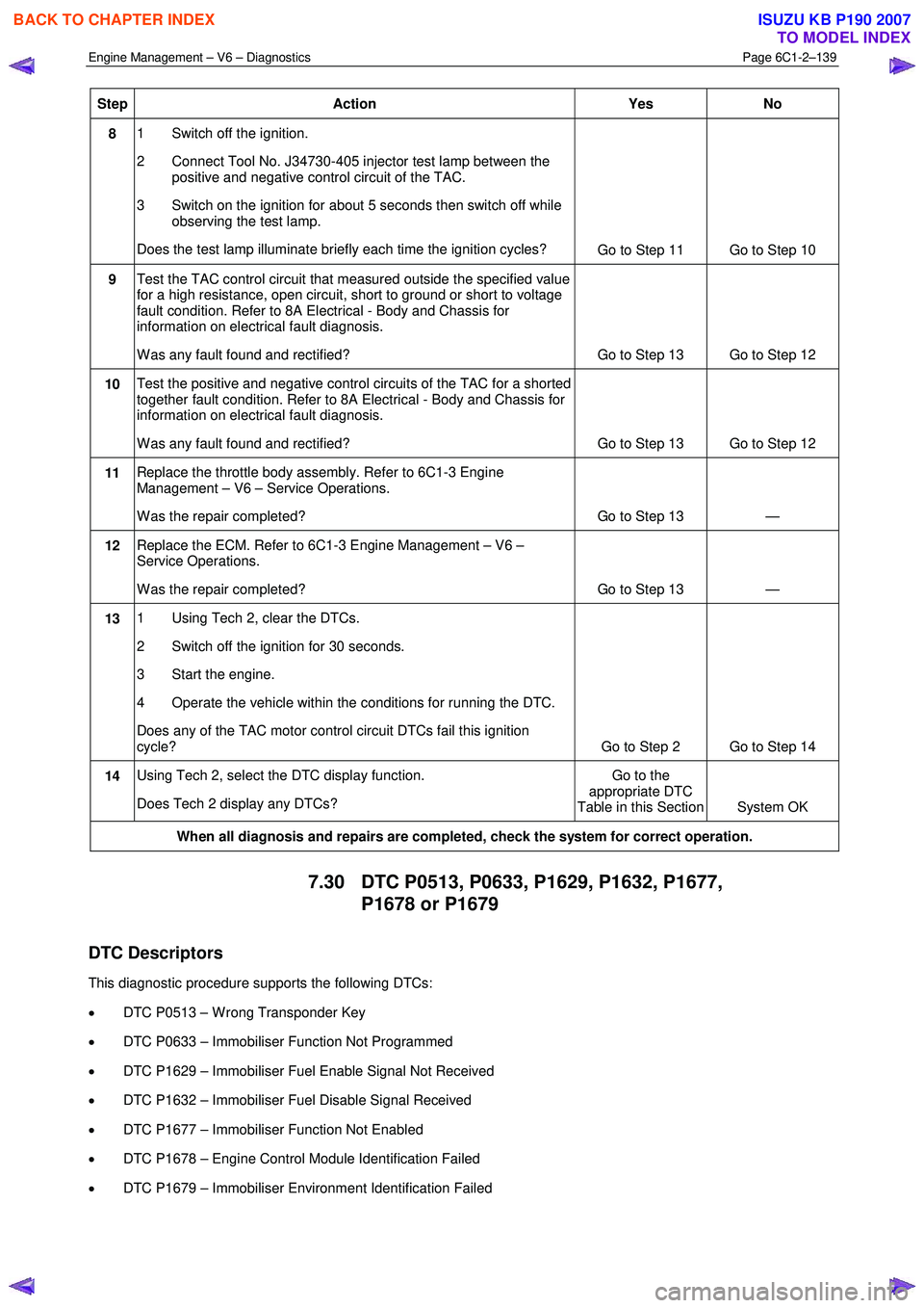
Step Action Yes
No
8 1 Switch off the ignition.
2 Connect Tool No. J34730-405 injector test lamp between the positive and negative control circuit of the TAC.
3 Switch on the ignition for about 5 seconds then switch off while observing the test lamp.
Does the test lamp illuminate briefly each time the ignition cycles? Go to Step 11 Go to Step 10
9 Test the TAC control circuit that measured outside the specified value
for a high resistance, open circuit, short to ground or short to voltage
fault condition. Refer to 8A Electrical - Body and Chassis for
information on electrical fault diagnosis.
W as any fault found and rectified? Go to Step 13 Go to Step 12
10 Test the positive and negative control circuits of the TAC for a shorted
together fault condition. Refer to 8A Electrical - Body and Chassis for
information on electrical fault diagnosis.
W as any fault found and rectified? Go to Step 13 Go to Step 12
11 Replace the throttle body assembly. Refer to 6C1-3 Engine
Management – V6 – Service Operations.
W as the repair completed? Go to Step 13 —
12 Replace the ECM. Refer to 6C1-3 Engine Management – V6 –
Service Operations.
W as the repair completed? Go to Step 13 —
13 1 Using Tech 2, clear the DTCs.
2 Switch off the ignition for 30 seconds.
3 Start the engine.
4 Operate the vehicle within the conditions for running the DTC.
Does any of the TAC motor control circuit DTCs fail this ignition
cycle? Go to Step 2 Go to Step 14
14 Using Tech 2, select the DTC display function.
Does Tech 2 display any DTCs? Go to the
appropriate DTC
Table in this Section System OK
When all diagnosis and repairs are completed, check the system for correct operation.
7.30 DTC P0513, P0633, P1629, P1632, P1677,
P1678 or P1679
DTC Descriptors
This diagnostic procedure supports the following DTCs:
• DTC P0513 – W rong Transponder Key
• DTC P0633 – Immobiliser Function Not Programmed
• DTC P1629 – Immobiliser Fuel Enable Signal Not Received
• DTC P1632 – Immobiliser Fuel Disable Signal Received
• DTC P1677 – Immobiliser Function Not Enabled
• DTC P1678 – Engine Control Module Identification Failed
• DTC P1679 – Immobiliser Environment Identification Failed
BACK TO CHAPTER INDEX
TO MODEL INDEX
ISUZU KB P190 2007
Page 3496 of 6020
Engine Management – V6 – Diagnostics Page 6C1-2–218
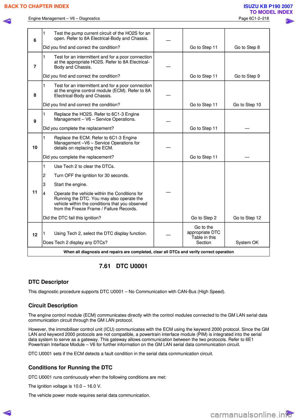
6 1 Test the pump current circuit of the HO2S for an
open. Refer to 8A Electrical-Body and Chassis.
Did you find and correct the condition? —
Go to Step 11 Go to Step 8
7 1 Test for an intermittent and for a poor connection
at the appropriate HO2S. Refer to 8A Electrical-
Body and Chassis.
Did you find and correct the condition? —
Go to Step 11 Go to Step 9
8 1 Test for an intermittent and for a poor connection
at the engine control module (ECM). Refer to 8A
Electrical-Body and Chassis.
Did you find and correct the condition? —
Go to Step 11 Go to Step 10
9 1 Replace the HO2S. Refer to 6C1-3 Engine
Management – V6 – Service Operations.
Did you complete the replacement? —
Go to Step 11 —
10 1 Replace the ECM. Refer to 6C1-3 Engine
Management –V6 – Service Operations for
details on replacing the ECM.
Did you complete the replacement? —
Go to Step 11 —
11 1 Use Tech 2 to clear the DTCs.
2 Turn OFF the ignition for 30 seconds.
3 Start the engine.
4 Operate the vehicle within the Conditions for Running the DTC. You may also operate the
vehicle within the conditions that you observed
from the Freeze Frame / Failure Records.
Did the DTC fail this ignition? —
Go to Step 2 Go to Step 12
12 1 Using Tech 2, select the DTC display function.
Does Tech 2 display any DTCs? —
Go to the
appropriate DTC Table in this Section System OK
When all diagnosis and repairs are completed, clear all DTCs and verify correct operation
7.61 DTC U0001
DTC Descriptor
This diagnostic procedure supports DTC U0001 – No Communication with CAN-Bus (High Speed).
Circuit Description
The engine control module (ECM) communicates directly with the control modules connected to the GM LAN serial data
communication circuit through the GM LAN protocol.
However, the immobiliser control unit (ICU) communicates with the ECM using the keyword 2000 protocol. Since the GM
LAN and keyword 2000 protocols are not compatible, a powertrain interface module (PIM) is integrated into the serial
data system to serve as a gateway. This gateway allows communication between the two protocols. Refer to 6E1
Powertrain Interface Module – V6 for further information on the GM LAN serial data communication circuit.
DTC U0001 sets if the ECM detects a fault condition in the serial data communication circuit.
Conditions for Running the DTC
DTC U0001 runs continuously when the following conditions are met:
The ignition voltage is 10.0 – 16.0 V.
The vehicle power mode requires serial data communication.
BACK TO CHAPTER INDEX
TO MODEL INDEX
ISUZU KB P190 2007