Page 2902 of 6020
Engine Mechanical – V6 Page 6A1–125
Page 6A1–125
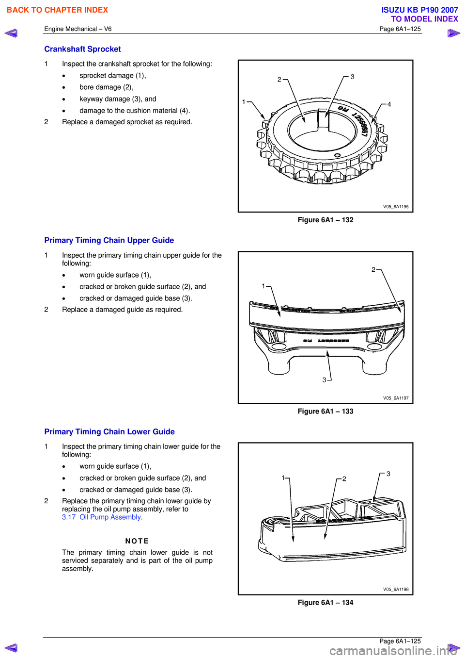
Crankshaft Sprocket
1 Inspect the crankshaft sprocket for the following:
• sprocket damage (1),
• bore damage (2),
• keyway damage (3), and
• damage to the cushion material (4).
2 Replace a damaged sprocket as required.
Figure 6A1 – 132
Primary Timing Chain Upper Guide
1 Inspect the primary timing chain upper guide for the following:
• worn guide surface (1),
• cracked or broken guide surface (2), and
• cracked or damaged guide base (3).
2 Replace a damaged guide as required.
Figure 6A1 – 133
Primary Timing Chain Lower Guide
1 Inspect the primary timing chain lower guide for the following:
• worn guide surface (1),
• cracked or broken guide surface (2), and
• cracked or damaged guide base (3).
2 Replace the primary timing chain lower guide by replacing the oil pump assembly, refer to
3.17 Oil Pump Assembly .
NOTE
The primary timing chain lower guide is not
serviced separately and is part of the oil pump
assembly.
Figure 6A1 – 134
BACK TO CHAPTER INDEX
TO MODEL INDEX
ISUZU KB P190 2007
Page 2907 of 6020
Engine Mechanical – V6 Page 6A1–130
Page 6A1–130
Reinstall
Left-hand Secondary Timing Chain Components – Excluding MY06 Update
1 Install the crankshaft sprocket (1) onto the
crankshaft (2) by aligning the keyway to the key on
the crankshaft.
2 Slide the crankshaft sprocket on the crankshaft until the crankshaft sprocket contacts the step in the
crankshaft.
Figure 6A1 – 144
NOTE
Ensure that the crankshaft sprocket is installed
with the timing mark (1) visible.
Figure 6A1 – 145
CAUTION
In order to install Tool No. EN 46105 onto the
camshafts, rotate the camshafts in an anti-
clockwise direction. There should be no
need to rotate the camshaft more than 45
degrees.
Figure 6A1 – 146
BACK TO CHAPTER INDEX
TO MODEL INDEX
ISUZU KB P190 2007
Page 2916 of 6020
Engine Mechanical – V6 Page 6A1–139
Page 6A1–139
34 Verify the left-hand secondary timing chain timing
mark alignments (1 to 6).
Figure 6A1 – 170
Left-hand Secondary Timing Chain Components – MY06 Update
1 Install the crankshaft sprocket (1) onto the crankshaft (2) by aligning the keyway to the key on
the crankshaft.
2 Slide the crankshaft sprocket on the crankshaft until the crankshaft sprocket contacts the step in the
crankshaft.
Figure 6A1 – 171
NOTE
Ensure that the crankshaft sprocket is installed
with the timing mark (1) visible.
Figure 6A1 – 172
BACK TO CHAPTER INDEX
TO MODEL INDEX
ISUZU KB P190 2007
Page 2996 of 6020
Engine Mechanical – V6 Page 6A1–219
Page 6A1–219
Disassemble
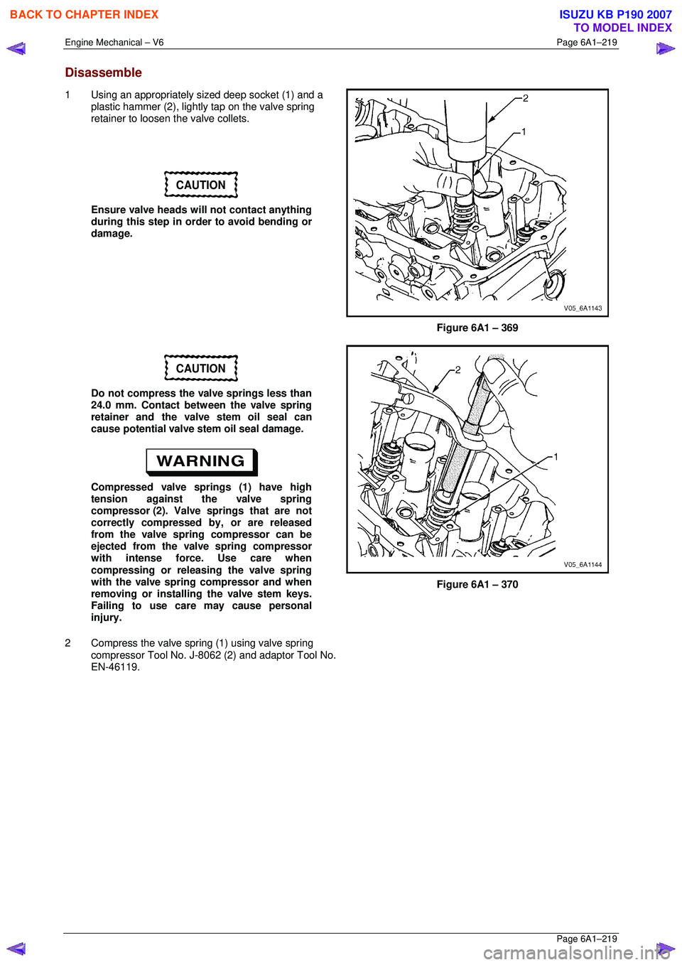
1 Using an appropriately sized deep socket (1) and a
plastic hammer (2), lightly tap on the valve spring
retainer to loosen the valve collets.
CAUTION
Ensure valve heads will not contact anything
during this step in order to avoid bending or
damage.
Figure 6A1 – 369
CAUTION
Do not compress the valve springs less than
24.0 mm. Contact between the valve spring
retainer and the valve stem oil seal can
cause potential valve stem oil seal damage.
Compressed valve springs (1) have high
tension against the valve spring
compressor (2). Valve springs that are not
correctly compressed by, or are released
from the valve spring compressor can be
ejected from the valve spring compressor
with intense force. Use care when
compressing or releasing the valve spring
with the valve spring compressor and when
removing or installing the valve stem keys.
Failing to use care may cause personal
injury.
2 Compress the valve spring (1) using valve spring compressor Tool No. J-8062 (2) and adaptor Tool No.
EN-46119.
Figure 6A1 – 370
BACK TO CHAPTER INDEX
TO MODEL INDEX
ISUZU KB P190 2007
Page 3003 of 6020
Engine Mechanical – V6 Page 6A1–226
Page 6A1–226
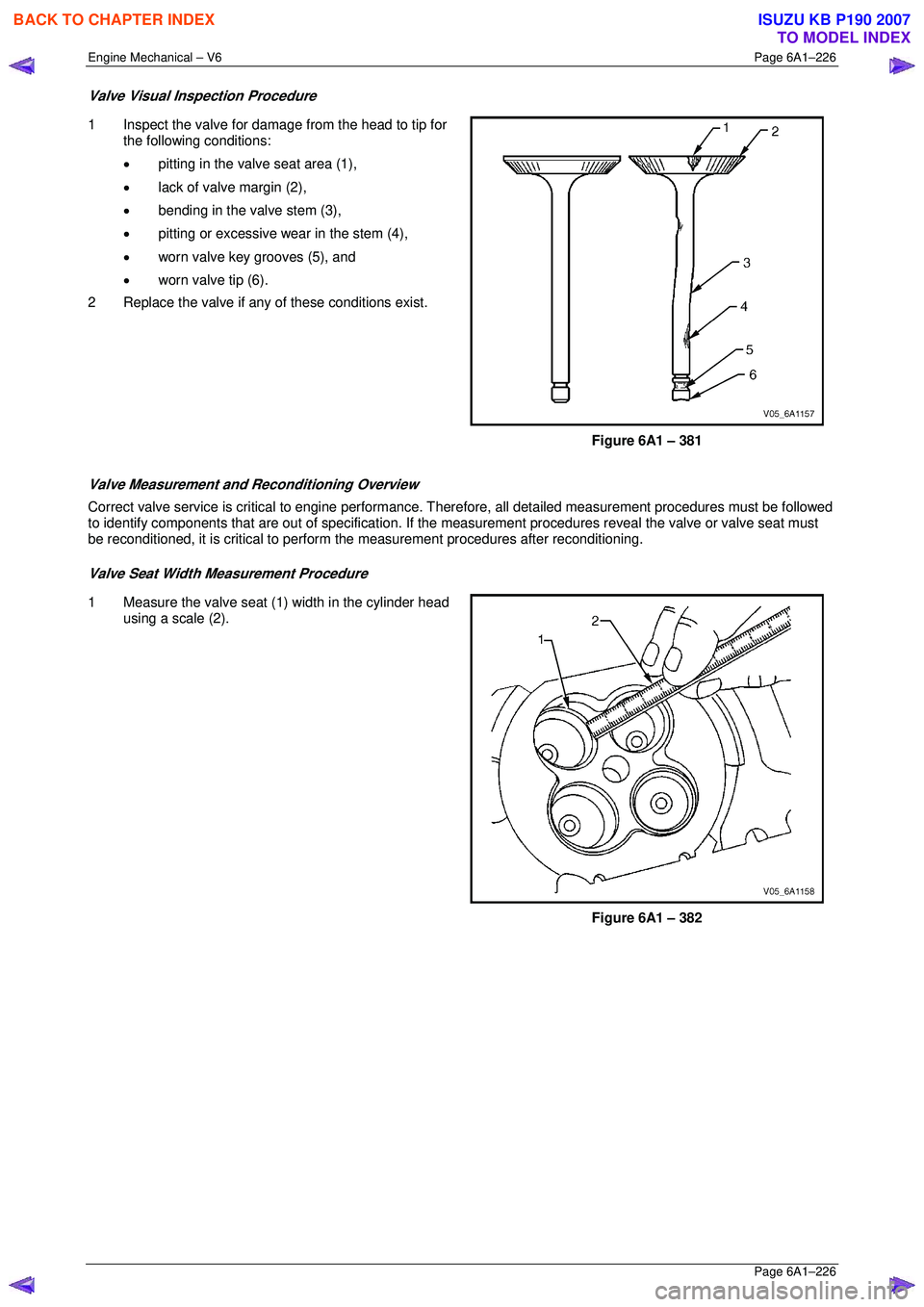
Valve Visual Inspection Procedure
1 Inspect the valve for damage from the head to tip for
the following conditions:
• pitting in the valve seat area (1),
• lack of valve margin (2),
• bending in the valve stem (3),
• pitting or excessive wear in the stem (4),
• worn valve key grooves (5), and
• worn valve tip (6).
2 Replace the valve if any of these conditions exist.
Figure 6A1 – 381
Valve Measurement and Reconditioning Overview
Correct valve service is critical to engine performance. Therefore, all detailed measurement procedures must be followed
to identify components that are out of specification. If the measurement procedures reveal t he valve or valve seat must
be reconditioned, it is critical to perform t he measurement procedures after reconditioning.
Valve Seat Width Measurement Procedure
1 Measure the valve seat (1) width in the cylinder head
using a scale (2).
Figure 6A1 – 382
BACK TO CHAPTER INDEX
TO MODEL INDEX
ISUZU KB P190 2007
Page 3006 of 6020
Engine Mechanical – V6 Page 6A1–229
Page 6A1–229
NOTE
• Clean any remaining lapping compound from
the valve and seat with solvent and
compressed air prior to final assembly.
• If fitting new valves, do not lap the valves
under any condition.
7 After obtaining the correct valve seat width in the cylinder head, measure the valve stem height, refer to Valve
Stem Height Measurement Pr ocedure in this Section.
8 If the valve stem height is acceptabl e, test the seats for concentricity, refer to Valve-to-Seat Concentricity
Measurement Procedure in this Section.
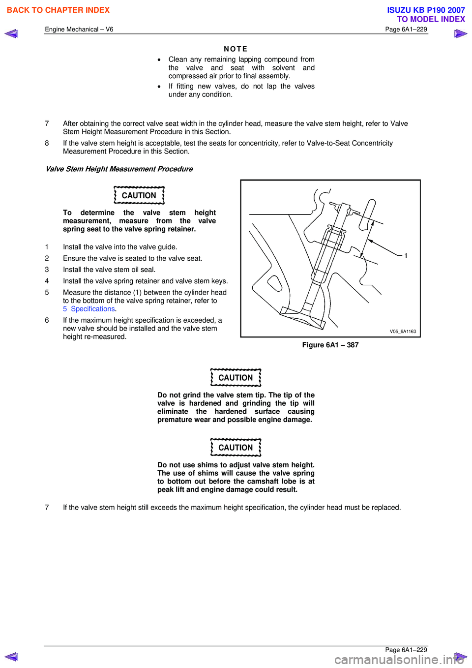
Valve Stem Height Measurement Procedure
CAUTION
To determine the valve stem height
measurement, measure from the valve
spring seat to the valve spring retainer.
1 Install the valve into the valve guide.
2 Ensure the valve is seated to the valve seat.
3 Install the valve stem oil seal.
4 Install the valve spring retainer and valve stem keys.
5 Measure the distance (1 ) between the cylinder head
to the bottom of the valve spring retainer, refer to
5 Specifications .
6 If the maximum height spec ification is exceeded, a
new valve should be installed and the valve stem
height re-measured.
Figure 6A1 – 387
CAUTION
Do not grind the valve stem tip. The tip of the
valve is hardened and grinding the tip will
eliminate the hardened surface causing
premature wear and possible engine damage.
CAUTION
Do not use shims to adjust valve stem height.
The use of shims will cause the valve spring
to bottom out before the camshaft lobe is at
peak lift and engine damage could result.
7 If the valve stem height still exceeds the maximum height specification, the cylinder head must be replaced.
BACK TO CHAPTER INDEX
TO MODEL INDEX
ISUZU KB P190 2007
Page 3008 of 6020
Engine Mechanical – V6 Page 6A1–231
Page 6A1–231
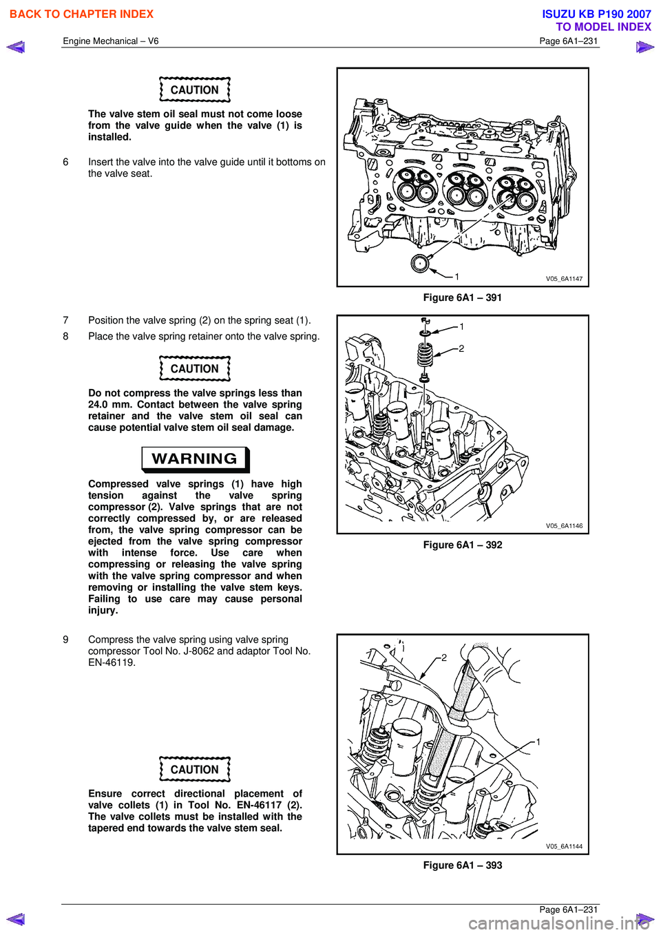
CAUTION
The valve stem oil seal must not come loose
from the valve guide when the valve (1) is
installed.
6 Insert the valve into the valve guide until it bottoms on
the valve seat.
Figure 6A1 – 391
7 Position the valve spring (2) on the spring seat (1).
8 Place the valve spring retainer onto the valve spring.
CAUTION
Do not compress the valve springs less than
24.0 mm. Contact between the valve spring
retainer and the valve stem oil seal can
cause potential valve stem oil seal damage.
Compressed valve springs (1) have high
tension against the valve spring
compressor (2). Valve springs that are not
correctly compressed by, or are released
from, the valve spring compressor can be
ejected from the valve spring compressor
with intense force. Use care when
compressing or releasing the valve spring
with the valve spring compressor and when
removing or installing the valve stem keys.
Failing to use care may cause personal
injury.
Figure 6A1 – 392
9 Compress the valve spring using valve spring compressor Tool No. J-8062 and adaptor Tool No.
EN-46119.
CAUTION
Ensure correct directional placement of
valve collets (1) in Tool No. EN-46117 (2).
The valve collets must be installed with the
tapered end towards the valve stem seal.
Figure 6A1 – 393
BACK TO CHAPTER INDEX
TO MODEL INDEX
ISUZU KB P190 2007
Page 3019 of 6020
Engine Mechanical – V6 Page 6A1–242
Page 6A1–242
Plug the fuel feed hose after removal to
prevent dirt entering the pipe.
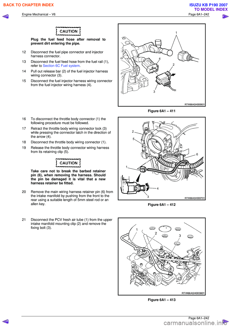
12 Disconnect the fuel pipe connector and injector harness connector.
13 Disconnect the fuel feed hose from the fuel rail (1),
refer to Section 6C Fuel system .
14 Pull out release bar (2) of the fuel injector harness
wiring connector (3).
15 Disconnect the fuel injector harness wiring connector from the fuel injector wiring harness (4).
Figure 6A1 – 411
16 To disconnect the throttle body connector (1) the following procedure must be followed.
17 Retract the throttle body wiring connector lock (3) while pressing the connector la tch in the direction of
the arrow (4).
18 Disconnect the throttle body wiring connector (1).
19 Release the throttle body connector wiring harness from its retaining clip (5).
Take care not to break the barbed retainer
pin (6), when removing the harness. Should
the pin be damaged it is vital that a new
harness retainer be fitted.
20 Remove the main wiring harness retainer pin (6) from the intake manifold by pushing from the front to the
rear using a suitable lengt h of 5mm steel rod or an
allen key.
Figure 6A1 – 412
21 Disconnect the PCV fresh air tube (1) from the upper intake manifold mounting clip (2) and remove the
fixing bolt (3).
Figure 6A1 – 413
BACK TO CHAPTER INDEX
TO MODEL INDEX
ISUZU KB P190 2007