2007 ISUZU KB P190 key
[x] Cancel search: keyPage 2240 of 6020
6E–70 ENGINE DRIVEABILITY AND EMISSIONS
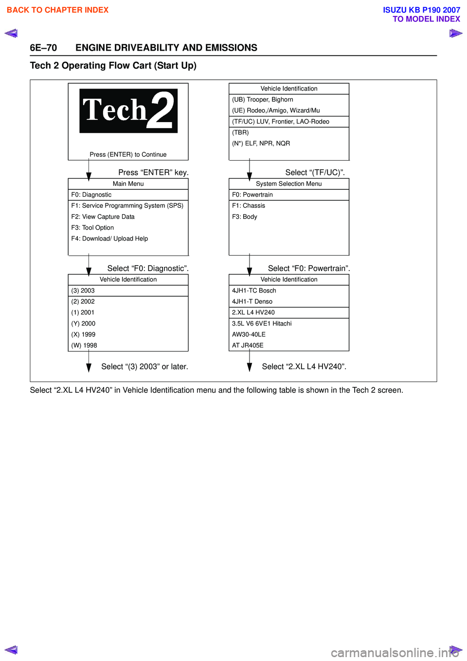
Tech 2 Operating Flow Cart (Start Up)
Select “2.XL L4 HV240” in Vehicle Identification menu and the following table is shown in the Tech 2 screen.
System Selection Menu
F0: Powertrain
F1: Chassis
F3: Body
Select “(TF/UC)”.
Vehicle Identification
4JH1-TC Bosch
4JH1-T Denso
2.XL L4 HV240
3.5L V6 6VE1 Hitachi
AW30-40LE
AT JR405E
Select “F0: Powertrain”.
Main Menu
F0: Diagnostic
F1: Service Programming System (SPS)
F2: View Capture Data
F3: Tool Option
F4: Download/ Upload Help
Press “ENTER” key.
Vehicle Identification
(3) 2003
(2) 2002
(1) 2001
(Y) 2000
(X) 1999
(W) 1998
Select “F0: Diagnostic”.
Select “(3) 2003” or later.
Press (ENTER) to Continue
Select “2.XL L4 HV240”.
Vehicle Identification
(UB) Trooper, Bighorn
(UE) Rodeo,/Amigo, Wizard/Mu
(TF/UC) LUV, Frontier, LAO-Rodeo
(TBR)
(N*) ELF, NPR, NQR
BACK TO CHAPTER INDEX
TO MODEL INDEX
ISUZU KB P190 2007
Page 2242 of 6020
6E–72 ENGINE DRIVEABILITY AND EMISSIONS
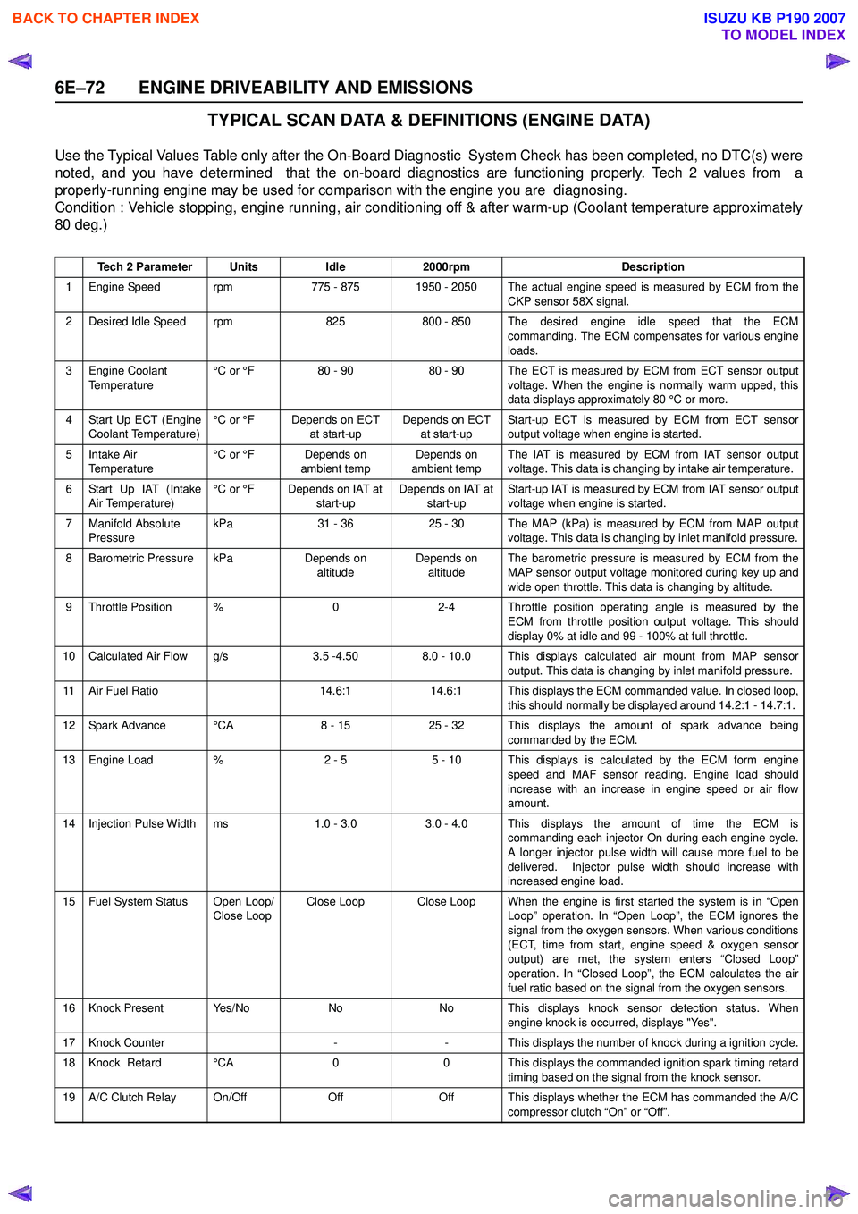
TYPICAL SCAN DATA & DEFINITIONS (ENGINE DATA)
Use the Typical Values Table only after the On-Board Diagnostic System Check has been completed, no DTC(s) were
noted, and you have determined that the on-board diagnostics are functioning properly. Tech 2 values from a
properly-running engine may be used for comparison with the engine you are diagnosing.
Condition : Vehicle stopping, engine running, air conditioning off & after warm-up (Coolant temperature approximately
80 deg.)
Tech 2 ParameterUnitsIdle2000rpmDescription
1 Engine Speed rpm775 - 8751950 - 2050 The actual engine speed is measured by ECM from the
CKP sensor 58X signal.
2 Desired Idle Speed rpm825800 - 850 The desired engine idle speed that the ECMcommanding. The ECM compensates for various engine
loads.
3 Engine Coolant Temperature °C or °F80 - 9080 - 90 The ECT is measured by ECM from ECT sensor output
voltage. When the engine is normally warm upped, this
data displays approximately 80 °C or more.
4 Start Up ECT (Engine Coolant Temperature) °C or °FDepends on ECT
at start-upDepends on ECT at start-up Start-up ECT is measured by ECM from ECT sensor
output voltage when engine is started.
5Intake Air
Temperature °C or °FDepends on
ambient tempDepends on
ambient temp The IAT is measured by ECM from IAT sensor output
voltage. This data is changing by intake air temperature.
6 Start Up IAT (Intake Air Temperature) °C or °FDepends on IAT at
start-upDepends on IAT at start-up Start-up IAT is measured by ECM from IAT sensor output
voltage when engine is started.
7 Manifold Absolute Pressure kPa31 - 3625 - 30The MAP (kPa) is measured by ECM from MAP output
voltage. This data is changing by inlet manifold pressure.
8 Barometric Pressure kPaDepends on altitudeDepends on altitude The barometric pressure is measured by ECM from the
MAP sensor output voltage monitored during key up and
wide open throttle. This data is changing by altitude.
9 Throttle Position %02-4 Throttle position operating angle is measured by the ECM from throttle position output voltage. This should
display 0% at idle and 99 - 100% at full throttle.
10 Calculated Air Flow g/s3.5 -4.508.0 - 10.0 This displays calculated air mount from MAP sensor output. This data is changing by inlet manifold pressure.
11 Air Fuel Ratio14.6:114.6:1 This displays the ECM commanded value. In closed loop,this should normally be displayed around 14.2:1 - 14.7:1.
12 Spark Advance °CA8 - 1525 - 32 This displays the amount of spark advance being commanded by the ECM.
13 Engine Load %2 - 55 - 10 This displays is calculated by the ECM form engine
speed and MAF sensor reading. Engine load should
increase with an increase in engine speed or air flow
amount.
14 Injection Pulse Width ms1.0 - 3.0 3.0 - 4.0 This displays the amount of time the ECM is commanding each injector On during each engine cycle.
A longer injector pulse width will cause more fuel to be
delivered. Injector pulse width should increase with
increased engine load.
15 Fuel System Status Open Loop/ Close LoopClose LoopClose Loop When the engine is first started the system is in “OpenLoop” operation. In “Open Loop”, the ECM ignores the
signal from the oxygen sensors. When various conditions
(ECT, time from start, engine speed & oxygen sensor
output) are met, the system enters “Closed Loop”
operation. In “Closed Loop”, the ECM calculates the air
fuel ratio based on the signal from the oxygen sensors.
16 Knock Present Yes/NoNoNo This displays knock sensor detection status. When engine knock is occurred, displays "Yes".
17 Knock Counter--This displays the number of knock during a ignition cycle.
18 Knock Retard °CA00 This displays the commanded ignition spark timing retard
timing based on the signal from the knock sensor.
19 A/C Clutch Relay On/OffOffOff This displays whether the ECM has commanded the A/C compressor clutch “On” or “Off”.
BACK TO CHAPTER INDEX
TO MODEL INDEX
ISUZU KB P190 2007
Page 2243 of 6020
ENGINE DRIVEABILITY AND EMISSIONS 6E–73
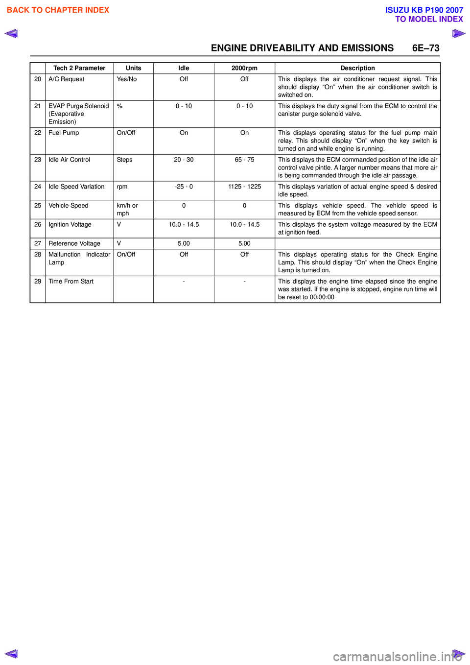
20 A/C Request Yes/NoOffOff This displays the air conditioner request signal. Thisshould display “On” when the air conditioner switch is
switched on.
21 EVAP Purge Solenoid (Evaporative
Emission) %0 - 100 - 10 This displays the duty signal from the ECM to control the
canister purge solenoid valve.
22 Fuel Pump On/OffOnOn This displays operating status for the fuel pump main
relay. This should display “On” when the key switch is
turned on and while engine is running.
23 Idle Air Control Steps20 - 3065 - 75 This displays the ECM commanded position of the idle air control valve pintle. A larger number means that more air
is being commanded through the idle air passage.
24 Idle Speed Variation rpm-25 - 01125 - 1225 This displays variation of actual engine speed & desired idle speed.
25 Vehicle Speed km/h or mph00This displays vehicle speed. The vehicle speed is
measured by ECM from the vehicle speed sensor.
26 Ignition Voltage V10.0 - 14.510.0 - 14.5 This displays the system voltage measured by the ECM at ignition feed.
27 Reference Voltage V5.005.00
28 Malfunction Indicator
Lamp On/OffOffOff This displays operating status for the Check Engine
Lamp. This should display “On” when the Check Engine
Lamp is turned on.
29Time From Start--This displays the engine time elapsed since the engine
was started. If the engine is stopped, engine run time will
be reset to 00:00:00
Tech 2 ParameterUnitsIdle2000rpmDescription
BACK TO CHAPTER INDEX
TO MODEL INDEX
ISUZU KB P190 2007
Page 2244 of 6020

6E–74 ENGINE DRIVEABILITY AND EMISSIONS
TYPICAL SCAN DATA & DEFINITIONS (O2 SENSOR DATA)
Use the Typical Values Table only after the On-Board Diagnostic System Check has been completed, no DTC(s) were
noted, and you have determined that the on-board diagnostics are functioning properly. Tech 2 values from a
properly-running engine may be used for comparison with the engine you are diagnosing.
Condition : Vehicle stopping, engine running, air conditioning off & after warm-up (Coolant temperature approximately
80 deg.)
Tech 2 ParameterUnitsIdle2000rpmDescription
1 Engine Speed rpm710 - 8751950 - 2050 The actual engine speed is measured by ECM from the
CKP sensor 58X signal.
2 Desired Idle Speed rpm825800 - 850 The desired engine idle speed that the ECMcommanding. The ECM compensates for various engine
loads.
3 Engine Coolant Temperature °C or °F80 - 9080 - 90 The ECT is measured by ECM from ECT sensor output
voltage. When the engine is normally warm upped, this
data displays approximately 80 °C or more.
4 Start Up ECT (Engine Coolant Temperature) °C or °FDepends on ECT
at start-upDepends on ECT at start-up Start-up ECT is measured by ECM from ECT sensor
output voltage when engine is started.
5Intake Air
Temperature °C or °FDepends on
ambient tempDepends on
ambient temp The IAT is measured by ECM from IAT sensor output
voltage. This data is changing by intake air temperature.
6 Start Up IAT (Intake Air Temperature) °C or °FDepends on IAT at
start-upDepends on IAT at start-up Start-up IAT is measured by ECM from IAT sensor output
voltage when engine is started.
7 Manifold Absolute Pressure kPa31 - 3625 - 30The MAP (kPa) is measured by ECM from MAP output
voltage. This data is changing by inlet manifold pressure.
8 Barometric Pressure kPaDepends on altitudeDepends on altitude The barometric pressure is measured by ECM from the
MAP sensor output voltage monitored during key up and
wide open throttle. This data is changing by altitude.
9 Throttle Position %02 - 4 Throttle position operating angle is measured by the ECM from throttle position output voltage. This should
display 0% at idle and 99 - 100% at full throttle.
10 Calculated Air Flow g/s3.5 -4.508.0 - 10.0 This displays intake air amount. The mass air flow is measured by ECM from the MAF sensor output voltage.
11 Air Fuel Ratio14.6:114.6:1 This displays the ECM commanded value. In closedloop, this should normally be displayed around 14.2:1 -
14.7:1.
12 Fuel System Status Open Loop/ Close LoopClose LoopClose Loop When the engine is first started the system is in “OpenLoop” operation. In “Open Loop”, the ECM ignores the
signal from the oxygen sensors. When various
conditions (ECT, time from start, engine speed & oxygen
sensor output) are met, the system enters “Closed Loop”
operation. In “Closed Loop”, the ECM calculates the air
fuel ratio based on the signal from the oxygen sensors.
13 Engine Load %2 - 55 - 10 This displays is calculated by the ECM form engine
speed and MAF sensor reading. Engine load should
increase with an increase in engine speed or air flow
amount.
14B1 O2 Sensor Ready
(Bank 1)Ye s / N oYe sYes This displays the status of the exhaust oxygen sensor. This display will indicate “Yes” when the ECM detects a
fluctuating oxygen sensor output voltage sufficient to
allow closed loop operation. This will not occur unless
the oxygen sensor is warmed up.
15B1S1 Status
(Bank 1 Sensor 1)Rich / LeanRich / LeanRich / Lean This displays dependent on the exhaust oxygen sensor output voltage. Should fluctuate constantly “Rich” and
“Lean” in closed loop.
16 Fuel Trim Learned Yes/NoYe sYes When conditions are appropriate for enabling long term fuel trim corrections, fuel trim learn will display “Yes”.
This indicates that the long term fuel trim is responding
to the short term fuel trim. If the fuel trim lean displays
“No”, then long term fuel trim will not respond to changes
in short term fuel trim.
BACK TO CHAPTER INDEX
TO MODEL INDEX
ISUZU KB P190 2007
Page 2246 of 6020
6E–76 ENGINE DRIVEABILITY AND EMISSIONS
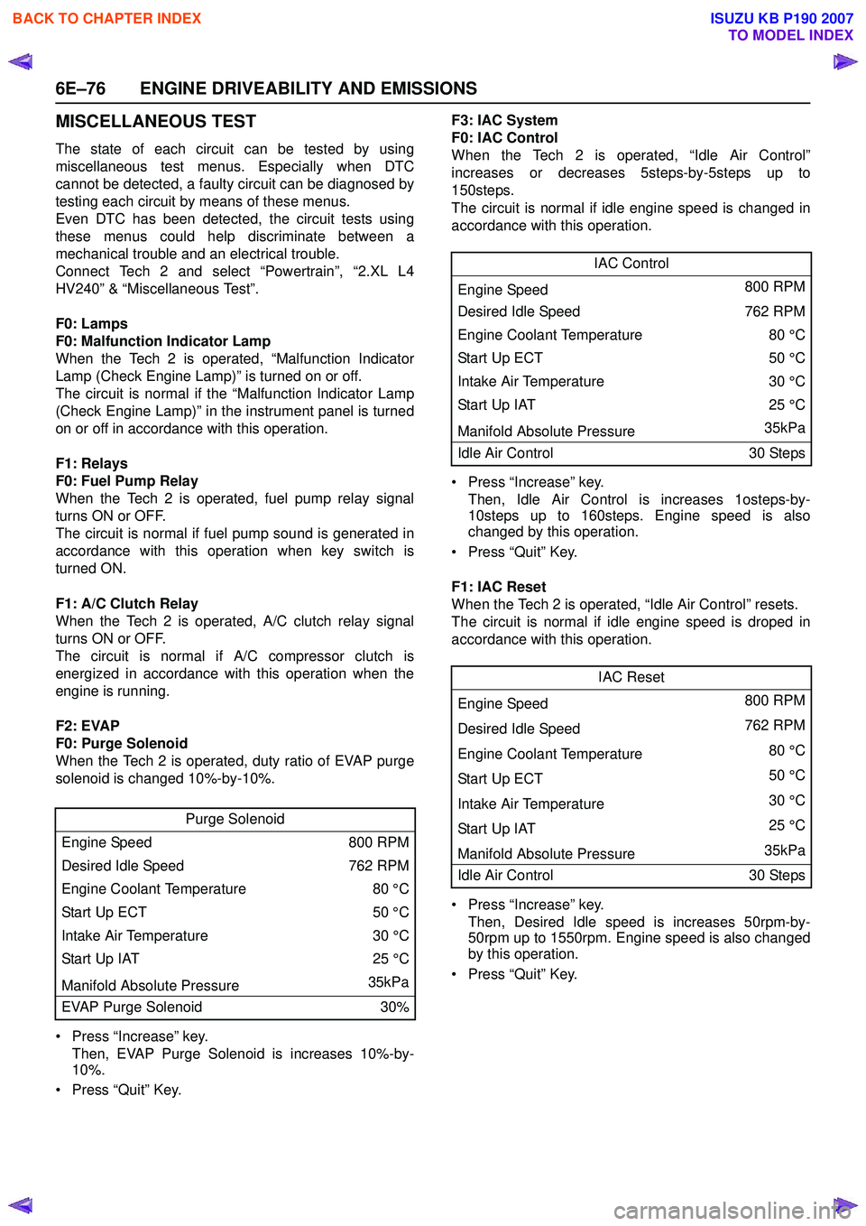
MISCELLANEOUS TEST
The state of each circuit can be tested by using
miscellaneous test menus. Especially when DTC
cannot be detected, a faulty circuit can be diagnosed by
testing each circuit by means of these menus.
Even DTC has been detected, the circuit tests using
these menus could help discriminate between a
mechanical trouble and an electrical trouble.
Connect Tech 2 and select “Powertrain”, “2.XL L4
HV240” & “Miscellaneous Test”.
F0: Lamps
F0: Malfunction Indicator Lamp
When the Tech 2 is operated, “Malfunction Indicator
Lamp (Check Engine Lamp)” is turned on or off.
The circuit is normal if the “Malfunction Indicator Lamp
(Check Engine Lamp)” in the instrument panel is turned
on or off in accordance with this operation.
F1: Relays
F0: Fuel Pump Relay
When the Tech 2 is operated, fuel pump relay signal
turns ON or OFF.
The circuit is normal if fuel pump sound is generated in
accordance with this operation when key switch is
turned ON.
F1: A/C Clutch Relay
When the Tech 2 is operated, A/C clutch relay signal
turns ON or OFF.
The circuit is normal if A/C compressor clutch is
energized in accordance with this operation when the
engine is running.
F2: EVAP
F0: Purge Solenoid
When the Tech 2 is operated, duty ratio of EVAP purge
solenoid is changed 10%-by-10%.
• Press “Increase” key. Then, EVAP Purge Solenoid is increases 10%-by-
10%.
• Press “Quit” Key. F3: IAC System
F0: IAC Control
When the Tech 2 is operated, “Idle Air Control”
increases or decreases 5steps-by-5steps up to
150steps.
The circuit is normal if idle engine speed is changed in
accordance with this operation.
• Press “Increase” key. Then, Idle Air Control is increases 1osteps-by-
10steps up to 160steps. Engine speed is also
changed by this operation.
• Press “Quit” Key.
F1: IAC Reset
When the Tech 2 is operated, “Idle Air Control” resets.
The circuit is normal if idle engine speed is droped in
accordance with this operation.
• Press “Increase” key. Then, Desired Idle speed is increases 50rpm-by-
50rpm up to 1550rpm. Engine speed is also changed
by this operation.
• Press “Quit” Key.
Purge Solenoid
Engine Speed 800 RPM
Desired Idle Speed 762 RPM
Engine Coolant Temperature 80 °C
Start Up ECT 50 °C
Intake Air Temperature 30 °C
Start Up IAT 25 °C
Manifold Absolute Pressure 35kPa
EVAP Purge Solenoid 30%
IAC Control
Engine Speed 800 RPM
Desired Idle Speed 762 RPM
Engine Coolant Temperature 80 °C
Sta rt U p E C T 50 °C
Intake Air Temperature 30 °C
Start Up IAT25 °C
Manifold Absolute Pressure 35kPa
Idle Air Control 30 Steps
IAC Reset
Engine Speed 800 RPM
Desired Idle Speed 762 RPM
Engine Coolant Temperature 80 °C
Sta rt U p E C T 50 °C
Intake Air Temperature 30 °C
Start Up IAT 25 °C
Manifold Absolute Pressure 35kPa
Idle Air Control 30 Steps
BACK TO CHAPTER INDEX
TO MODEL INDEX
ISUZU KB P190 2007
Page 2247 of 6020
ENGINE DRIVEABILITY AND EMISSIONS 6E–77
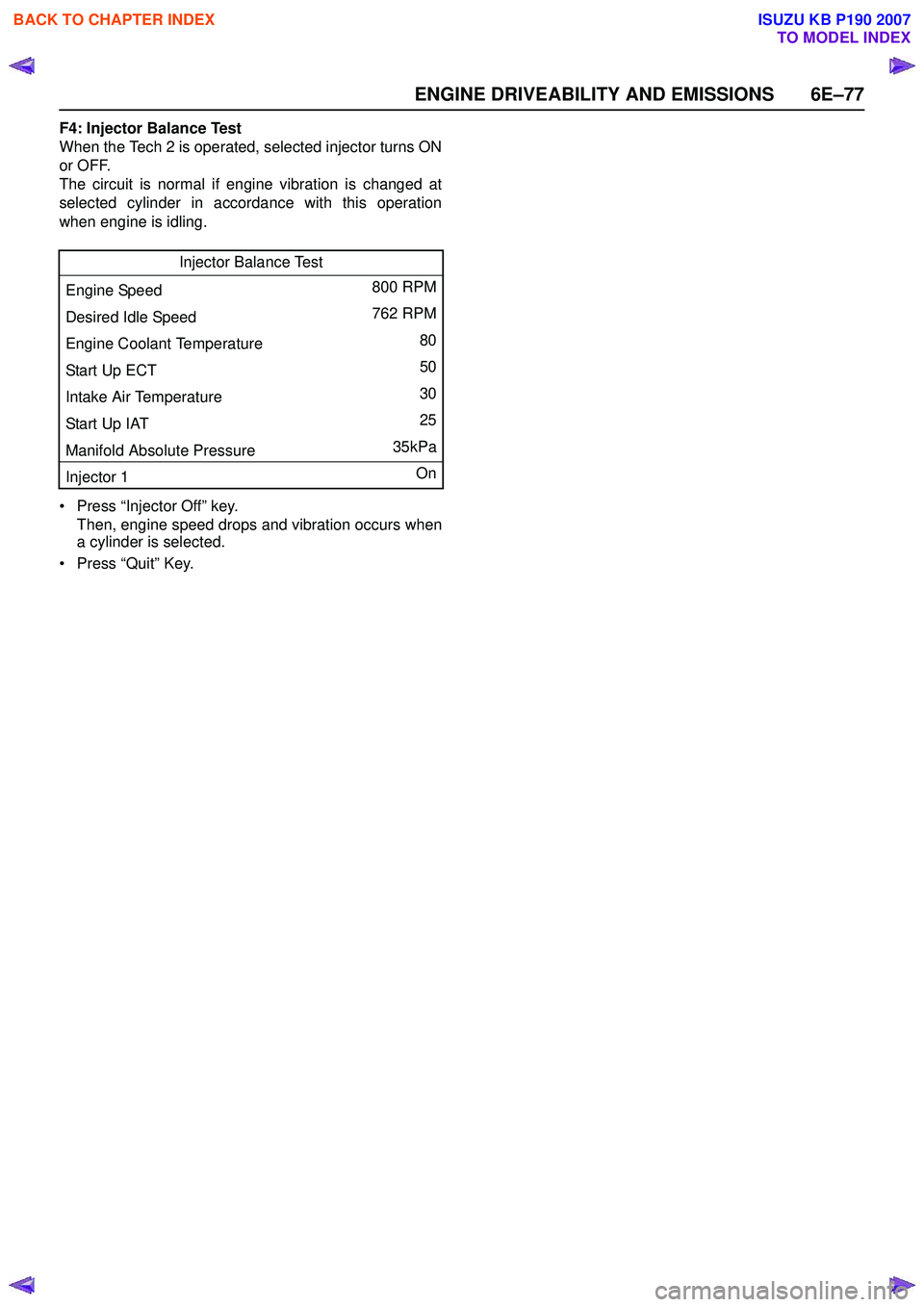
F4: Injector Balance Test
When the Tech 2 is operated, selected injector turns ON
or OFF.
The circuit is normal if engine vibration is changed at
selected cylinder in accordance with this operation
when engine is idling.
• Press “Injector Off” key. Then, engine speed drops and vibration occurs when
a cylinder is selected.
• Press “Quit” Key. Injector Balance Test
Engine Speed 800 RPM
Desired Idle Speed 762 RPM
Engine Coolant Temperature 80
Start Up ECT 50
Intake Air Temperature 30
Start Up IAT 25
Manifold Absolute Pressure 35kPa
Injector 1 On
BACK TO CHAPTER INDEX
TO MODEL INDEX
ISUZU KB P190 2007
Page 2254 of 6020
6E–84 ENGINE DRIVEABILITY AND EMISSIONS
SERVICE PROGRAMMING SYSTEM (SPS)
The procedure to program the control unit by using the
Service Programming System (SPS) software contained
in TIS2000 is explained below.
NOTE:
• If the Engine Control Module (ECM) was programmed, the Immobilizer System must be
linked to the ECM: Refer to section 11
“Immobilizer System-ECM replacement” for the
ECM/Immobilizer linking procedure.
• Should Tech2 display "SPS Procedure was not successful", engine will not start, but no DTCs
are present, low battery voltage or poor electrical
connections should be the primary suspects.
Perform the SPS procedure again after rectifying
the fault/s. IMPORTANT:
Perform the following checks before attempting to
program the control unit:
• The Tech2 PCMCIA card is programmed with The latest software release.
• The latest release of TIS2000 is loaded on the PC.
• The vehicle battery is fully charged.
• The control unit to be programmed is connected to the vehicle.
1. Preparations of TIS 2000 1. Connect Tech 2 to P/C.
2. Check to see if Hardware Key is plugged into Port.
3. Activate TIS 2000 by P/C.
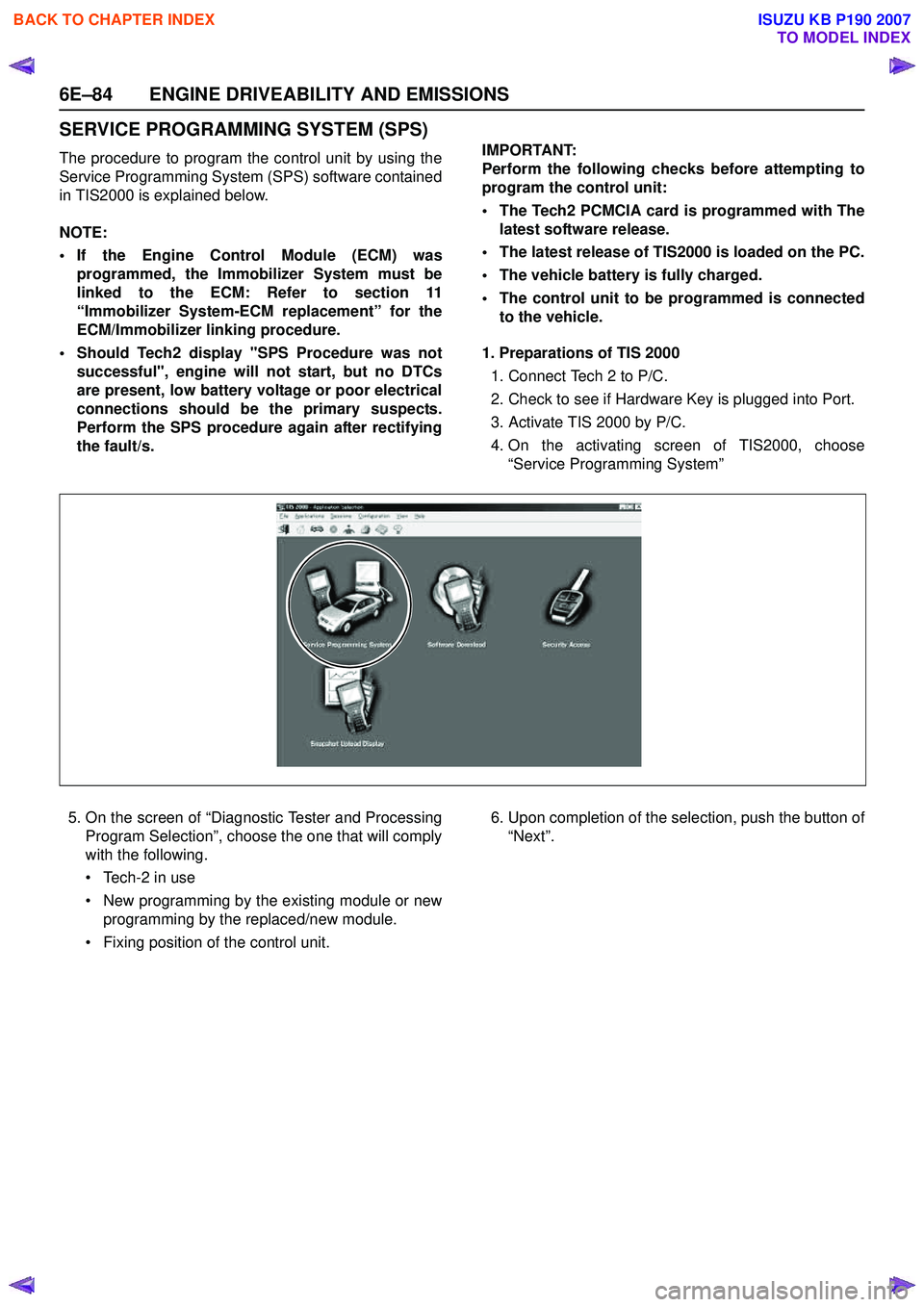
4. On the activating screen of TIS2000, choose “Service Programming System”
5. On the screen of “Diagnostic Tester and Processing Program Selection”, choose the one that will comply
with the following.
• Tech-2 in use
• New programming by the existing module or new programming by the replaced/new module.
• Fixing position of the control unit. 6. Upon completion of the selection, push the button of
“Next”.
BACK TO CHAPTER INDEX
TO MODEL INDEX
ISUZU KB P190 2007
Page 2288 of 6020
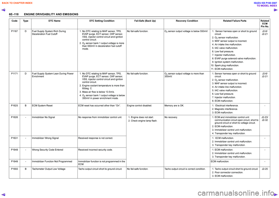
6E–118 ENGINE DRIVEABILITY AND EMISSIONSP1167 D Fuel Supply System Rich During
Deceleration Fuel Cutoff 1. No DTC relating to MAP sensor, TPS,
EVAP purge, ECT sensor, CKP sensor,
VSS, injector control circuit and ignition
control circuit.
2. O
2 sensor bank 1 output voltage is more
than 550mV in deceleration fuel cutoff
mode. No fail-safe function.
O
2 sensor output voltage is below 550mV. 1. Sensor harness open or short to ground
circuit.
2. O
2 sensor malfunction.
3. MAF sensor output is incorrect.
4. Air intake line malfunction.
5. IAC valve malfunction.
6. Low fuel pressure.
7. Injector malfunction.
8. EVAP purge solenoid valve malfunction.
9. Ignition system malfunction.
10. Spark plug malfunction. 11. ECM malfunction. J2-6/
J2-21
P1171 D Fuel Supply System Lean During Power Enrichment 1. No DTC relating to MAP sensor, TPS,
EVAP purge, ECT sensor, CKP sensor,
VSS, injector control circuit and ignition
control circuit.
2. Engine coolant temperature is more than 60deg. C.
3. Mass air flow is below 13.5m/s.
4. O
2 sensor bank 1 output voltage is below
350mV in power enrichment mode. No fail-safe function.
O
2 sensor output voltage is more than
350mV. 1. Sensor harness open or short to ground
circuit.
2. O
2 sensor malfunction.
3. MAF sensor output is incorrect.
4. Air intake line malfunction.
5. IAC valve malfunction.
6. Low fuel pressure.
7. Injector malfunction.
8. ECM malfunction. J2-6/
J2-21
P1625 B ECM System Reset ECM reset has occurred other than “On ”. Engine control disabled. Memory are is OK. 1. Electrical interference.
2. Magnetic interference.
3. ECM malfunction. -
P1626 - Immobilizer No Signal No response from immobilizer control unit. 1. Engine does not start.
2. Check engine lamp flash.No recovery.
1. ECM and immobilizer control unit
communication circuit open circuit, short to
ground circuit or short to voltage circuit.
2. ECM malfunction.
3. Immobilizer control unit malfunction.
4. Transponder key malfunction. J2-23/
J2-32
P1631 - Immobilizer Wrong Signal Received response is not correct. 1. ECM malfunction.
2. Immobilizer control unit malfunction.
3. Transponder key malfunction. -
P1648 - Wrong Security Code Entered Received incorrect security code. 1. ECM malfunction.
2. Immobilizer control unit malfunction.
3. Transponder key malfunction. -
P1649 - Immobilizer Function Not Programmed Immobilizer function is not programmed in the ECM. ECM malfunction.
-
P1693 B Tachometer Output Low Voltage Tacho output circuit short to ground circuit. No fail-safe function. Tacho output circuit is correct condition. 1. Tacho output circuit short to ground circuit.
2. Poor connector connection.
3. ECM malfunction. J2-25
Code Type
DTC Name DTC Setting Condition Fail-Safe (Back Up)Recovery Condition Related Failure PartsRelated
ECM
Pin No.
BACK TO CHAPTER INDEX
TO MODEL INDEX
ISUZU KB P190 2007