2007 ISUZU KB P190 key
[x] Cancel search: keyPage 2166 of 6020
6D3-18 STARTING AND CHARGING SYSTEM
Reassembly
Generator
(a) Press new bearing onto slipring end of the rotor taking care to aplly the force to the bearing inner race only, otherwise
the bearing will be noisy and it's life will be shortened.
(b) Fit a new bearing to the drive end housing, fit the bearing plate, and four retaining screws, press the rotor into the
bearing, using a support tool to take the thrust against the
bearing inner.
The support is fitted from the pulley side of the bearing. In this way the thrust is not taken by the drive end housing.
(c) To fit pulley, mount an 8mm Allen key in the vice with the short end upwards, place a 24mm ring spanner on the shaft
nut, position the internal hexagon of the rotor shaft onto the
Allen key, tighten the nut to the required torque(See torque
chart)
(d) Inspect the bearing support ring for signs of damage, if in doubt replace the ring by pressing it into the housing b
y
hand, do not use excessive force.
(e) To refit the rectifier, fit new mica washers to the positive heatsink B+ bolt and retaining screw each washer must
have heatsink compound applied to both surfaces before
fitting.
Fit the three retaining screws to the rectifier then install into slipring end housing. Tighten the B+ bolt to the reuired
torque.
(f) To refit the stator, make sure the spigot surface are clean and free from damage, fit the stator into the slipring end
housing noting the correct lead connection positioning. Fit
the stator leads into the wire loops in the recrifier. Using a
pair of pliers squeeze the loop to retain the stator lead prior
to soldering. Repeat for each lead in turn, solder the leads
into position using 60/40 resin cored solder. Make sure the
leads will be clear of the internal fan when the rotor is
assmebled into the stator.
(g) Carefully install the rotor into the stator/slipring end housing assembly, noting the alignment of the housings and through
bolt holes. Fit the through bolts making sure the stator is
seated correctly, tighten the through bolts to the correct
torque setting (uneven torque can produce magnetic noise
levels above normal).
(h) Fitting the regulator. Compress the brushes into the brush holder by hand, slip the regulator through the opening in the
rear of the slipring end housing until the brushes come in
contact with the slipring. Press the regulator towards the
slipring until the holes are aligned then fit the retaining
screws and tighten.
BACK TO CHAPTER INDEX
TO MODEL INDEX
ISUZU KB P190 2007
Page 2212 of 6020

6E–42 ENGINE DRIVEABILITY AND EMISSIONS
ECM CONNECTOR PIN ASSIGNMENT & OUTPUT SIGNAL
Connector J1 Port: View Looking Into ECM Case
1
17 16
32
PIN16
PIN1
PIN17 PIN32
Pin
No. B/
Box
No. Pin Function
Wire
Color Signal or Continuity
ECM
Connection Tester Position
Key SW Off Key SW
On Engine
Idle Engine
2000rpm Range (+) (-)
J1-1 J1-1 Ground BLK/
WHT Continuity
with
ground -
- - Disconnect ΩJ1-1 GND
J1-2 J1-2 Ground BLK/
WHT Continuity
with
ground -
- - Disconnect ΩJ1-2 GND
J1-3 J1-3 Knock Sensor Signal YEL Less than 1V--- ----
J1-4 J1-4 No Connection - --- - -- - -
J1-5 J1-5 Canister Purge Solenoid Valve RED/
YEL Less than
1V Wave form G or 12-14V
Connect DC V J1-5 GND
J1-6 J1-6 Crankshaft Position (CKP) Sensor (Ground) RED Approx.
0.58kΩ -
- - Disconnect ΩJ1-6 J1-21
J1-7 J1-7 Throttle Position Sensor (TPS) Output
Signal BLU Less than
1V Approx 0.7V Approx
0.8VConnect DC V J1-7 J1-32
J1-8 J1-8 No. 3 Injector GRN/
BLK Less than
1V Wave form E or 12-14V
Connect DC V J1-8 GND
J1-9 J1-9 No. 1 Injector GRN/
WHT Less than
1V Wave form E or 12-14V
Connect DC V J1-9 GND
J1-10 J1-10 No Connection - --- - -- - -
J1-11 J1-11 No. 4 Injector GRN Less than
1V Wave form E or 12-14V
Connect DC V J1-11 GND
J1-12 J1-12 No Connection - --- - -- - -
J1-13 J1-13 Idle Air Control Valve (IACV) Coil B High BLU/
RED Less than
1V Less than 1V / 10-14V
Connect DC V J1-13 GND
J1-14 J1-14 No Connection - --- - -- - -
J1-15 J1-15 Throttle Position Sensor (TPS) Power
Supply RED Less than
1V Approx. 5V
Connect DC V J1-15 J1-32
J1-16 J1-16 MAP Sensor Ground GRN Continuity with
ground -
- - Connect ΩJ1-16 GND
J1-17 J1-17 Ground BLK/
WHT Continuity
with
ground -
- - Connect ΩJ1-17 GND
J1-18 J1-18 Coil Module 2 (No. 2 & 3 Cylinder) BLU -
-Wave form F -- - -
J1-19 J1-19 Coil Module 1 (No. 1 & 4 Cylinder) GRN -
-Wave form F -- - -
J1-20 J1-20 No Connection - --- - -- - -
BACK TO CHAPTER INDEX
TO MODEL INDEX
ISUZU KB P190 2007
Page 2213 of 6020

ENGINE DRIVEABILITY AND EMISSIONS 6E–43
J1-21 J1-21 Crankshaft Position (CKP) Sensor Signal WHT - - Wave form
or approx. 3.7V Wave form
A or
approx. 7.8V Connect AC V J1-21 J1-6
J1-22 J1-22 No.2 Injector GRN/
WHT Less than
1V Wave form E or 12-14V
Connect DC V J1-22 GND
J1-23 J1-23 No Connection - --- - -- - -
J1-24 J1-24 MAP Sensor Signal GRY Less than 1VApprox.
4.8V Approx.
1.3V Approx.
0.9V Connect DC V J1-24 J1-16
J1-25 J1-25 No Connection - --- - -- - -
J1-26 J1-26 No Connection - --- - -- J1-26 -
J1-27 J1-27 Engine Coolant Temp. (ECT) Sensor Signal GRY Less than
1V
20℃: Approx. 2.4V / 40 ℃: Approx. 1.4V or
4.1V / 60 ℃: Approx. 3.3V / 80 ℃: Approx.
2.5VConnect DC V J1-27 J1-32
J1-28 J1-28 Idle Air Control Valve (IACV) Coil A High BLU Less than
1V Less than 1V / 10-14V
Connect DC V J1-28 GND
J1-29 J1-29 Idle Air Control Valve (IACV) Coil B Low BLU/
BLK Less than
1V Less than 1V / 10-14V
Connect DC V J1-29 GND
J1-30 J1-30 Idle Air Control Valve (IACV) Coil A Low BLU/
WHT Less than
1V Less than 1V / 10-14V
Connect DC V J1-30 GND
J1-31 J1-31 MAP Sensor Power Supply RED Less than
1V Approx.. 5V
Connect DC V J1-31 J1-16
J1-32 J1-32 ECT Sensor, Knock Sensor, Throttle
Position Sensor Ground GRN Continuity
with
ground -
- - Connect ΩJ1-32 GND
Pin
No. B/
Box No. Pin Function
Wire
Color Signal or Continuity
ECM
Connection Tester Position
Key SW Off Key SW
On Engine
Idle Engine
2000rpm Range (+) (-)
BACK TO CHAPTER INDEX
TO MODEL INDEX
ISUZU KB P190 2007
Page 2214 of 6020
6E–44 ENGINE DRIVEABILITY AND EMISSIONS
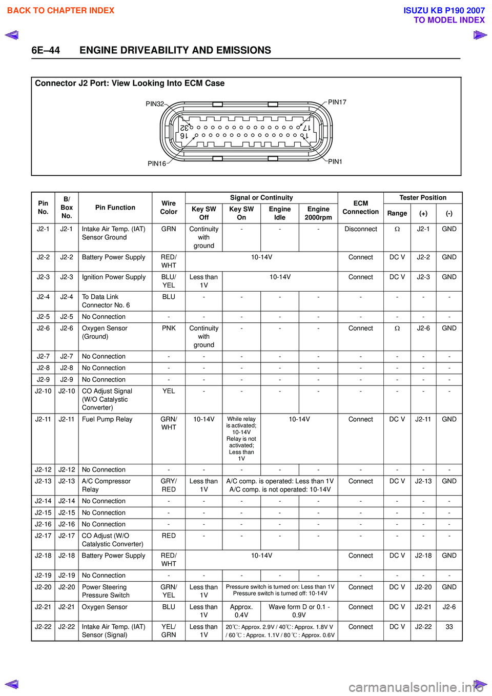
Connector J2 Port: View Looking Into ECM Case
1
17 16
32
PIN32
PIN1
PIN17
PIN16
Pin
No. B/
Box No. Pin Function
Wire
Color Signal or Continuity
ECM
Connection Tester Position
Key SW Off Key SW
On Engine
Idle Engine
2000rpm Range (+) (-)
J2-1 J2-1 Intake Air Temp. (IAT) Sensor Ground GRN Continuity
with
ground -
- - Disconnect ΩJ2-1 GND
J2-2 J2-2 Battery Power Supply RED/ WHT10-14V
Connect DC V J2-2 GND
J2-3 J2-3 Ignition Power Supply BLU/ YELLess than
1V 10-14V
Connect DC V J2-3 GND
J2-4 J2-4 To Data Link Connector No. 6 BLU -
-- - -- - -
J2-5 J2-5 No Connection -- - - - -- - -
J2-6 J2-6 Oxygen Sensor (Ground) PNK Continuity
with
ground -
- - Connect ΩJ2-6 GND
J2-7 J2-7 No Connection -- - - - -- - -
J2-8 J2-8 No Connection -- - - - -- - -
J2-9 J2-9 No Connection -- - - - -- - -
J2-10 J2-10 CO Adjust Signal (W/O Catalystic
Converter) YEL -
-- - -- - -
J2-11 J2-11 Fuel Pump Relay GRN/ WHT10-14V
While relay
is activated; 10-14V
Relay is not
activated;
Less than 1V10-14V Connect DC V J2-11 GND
J2-12 J2-12 No Connection -- - - - -- - -
J2-13 J2-13 A/C Compressor Relay GRY/
RED Less than
1V A/C comp. is operated: Less than 1V
A/C comp. is not operated: 10-14V Connect DC V J2-13 GND
J2-14 J2-14 No Connection -- - - - -- - -
J2-15 J2-15 No Connection -- - - - -- - -
J2-16 J2-16 No Connection -- - - - -- - -
J2-17 J2-17 CO Adjust (W/O Catalystic Converter) RED -
-- - -- - -
J2-18 J2-18 Battery Power Supply RED/ WHT10-14V
Connect DC V J2-18 GND
J2-19 J2-19 No Connection -- - - - -- - -
J2-20 J2-20 Power Steering Pressure Switch GRN/
YEL Less than
1V
Pressure switch is turned on: Less than 1VPressure switch is turned off: 10-14VConnect DC V J2-20 GND
J2-21 J2-21 Oxygen Sensor BLU Less than 1VApprox.
0.4V Wave form D or 0.1 -
0.9V Connect DC V J2-21 J2-6
J2-22 J2-22 Intake Air Temp. (IAT) Sensor (Signal) YEL/
GRN Less than
1V
20℃: Approx. 2.9V / 40 ℃: Approx. 1.8V V
/ 60 ℃: Approx. 1.1V / 80 ℃: Approx. 0.6VConnect DC V J2-22 33
BACK TO CHAPTER INDEX
TO MODEL INDEX
ISUZU KB P190 2007
Page 2215 of 6020
ENGINE DRIVEABILITY AND EMISSIONS 6E–45
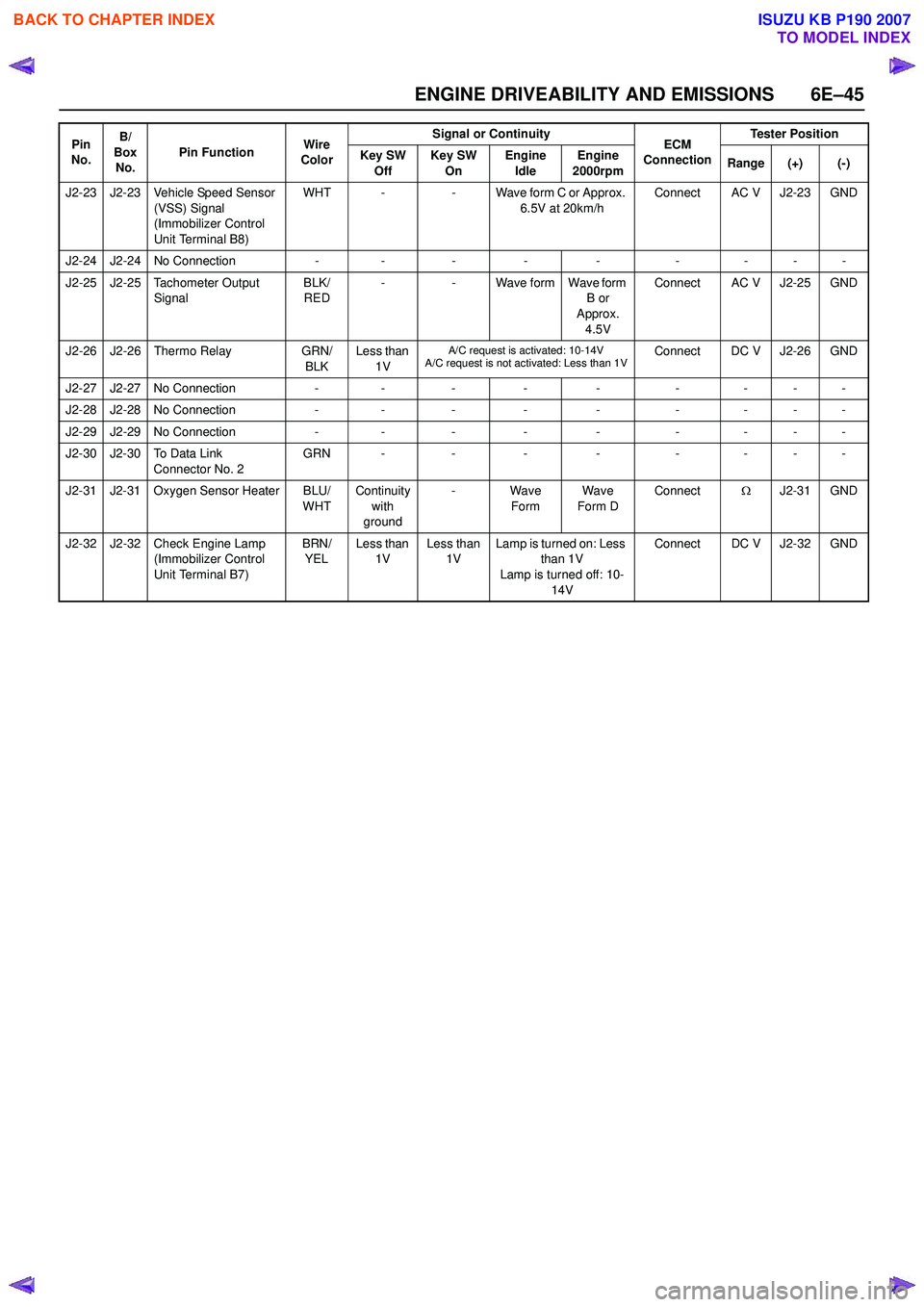
J2-23 J2-23 Vehicle Speed Sensor (VSS) Signal
(Immobilizer Control
Unit Terminal B8) WHT -
- Wave form C or Approx.
6.5V at 20km/h Connect AC V J2-23 GND
J2-24 J2-24 No Connection -- - - - -- - -
J2-25 J2-25 Tachometer Output Signal BLK/
RED -
- Wave form Wave form
B or
Approx.
4.5V Connect AC V J2-25 GND
J2-26 J2-26 Thermo Relay GRN/
BLK Less than
1V
A/C request is activated: 10-14V
A/C request is not activated: Less than 1VConnect DC V J2-26 GND
J2-27 J2-27 No Connection - - - - - - - - -
J2-28 J2-28 No Connection - - - - - - - - -
J2-29 J2-29 No Connection -- - - - -- - -
J2-30 J2-30 To Data Link Connector No. 2 GRN -
-- - -- - -
J2-31 J2-31 Oxygen Sensor Heater BLU/ WHTContinuity
with
ground - Wave
Form Wave
Form D Connect
ΩJ2-31 GND
J2-32 J2-32 Check Engine Lamp (Immobilizer Control
Unit Terminal B7) BRN/
YEL Less than
1V Less than
1V Lamp is turned on: Less
than 1V
Lamp is turned off: 10-
14V Connect DC V J2-32 GND
Pin
No. B/
Box No. Pin Function
Wire
Color Signal or Continuity
ECM
Connection Tester Position
Key SW Off Key SW
On Engine
Idle Engine
2000rpm Range (+) (-)
BACK TO CHAPTER INDEX
TO MODEL INDEX
ISUZU KB P190 2007
Page 2219 of 6020

ENGINE DRIVEABILITY AND EMISSIONS 6E–49
Throttle Position Sensor (TPS)
The TPS is a potentiometer connected to throttle shaft
on the throttle body.
The engine control module (ECM) monitors the voltage
on the signal line and calculates throttle position. As the
throttle valve angle is changed when accelerator pedal
moved. The TPS signal also changed at a moved
throttle valve. As the throttle valve opens, the output
increases so that the output voltage should be high.
The throttle body has a throttle plate to control the
amount of the air delivered to the engine.
Engine coolant is directed through a coolant cavity in
the throttle body to warm the throttle valve and to
prevent icing.
Idle Air Control (IAC) Valve
The idle air control valve (IAC) valve is two directional
and gives 2-way control. With power supply to the coils
controlled steps by the engine control module (ECM),
the IAC valve's pintle is moved to adjust idle speed,
raising it for fast idle when cold or there is extra load
from the air conditioning or power steering.
By moving the pintle in (to decrease air flow) or out (to
increase air flow), a controlled amount of the air can
move around the throttle plate. If the engine speed is
too low, the engine control module (ECM) will retract the
IAC pintle, resulting in more air moving past the throttle
plate to increase the engine speed.
If the engine speed is too high, the engine control
module (ECM) will extend the IAC pintle, allowing less
air to move past the throttle plate, decreasing the
engine speed.
The IAC pintle valve moves in small step called counts.
During idle, the proper position of the IAC pintle is
calculated by the engine control module (ECM) based
on battery voltage, coolant temperature, engine load,
and engine speed.
If the engine speed drops below a specified value, and
the throttle plate is closed, the engine control module
(ECM) senses a near-stall condition. The engine control
module (ECM) will then calculate a new IAC pintle valve
position to prevent stalls.
If the IAC valve is disconnected and reconnected with
the engine running, the idle speed will be wrong. In this
case, the IAC must be reset. The IAC resets when the
key is cycled “On” then “Off”. When servicing the IAC, it
should only be disconnected or connected with the
ignition “Off”.
The position of the IAC pintle valve affects engine start-
up and the idle characteristic of the vehicle.
If the IAC pintle is fully open, too much air will be
allowed into the manifold. This results in high idle
speed, along with possible hard starting and lean air/
fuel ratio.
(1) Throttle Position Sensor
(2) Idle Air Control (IAC) Valve
1
2
C harac teris t ic of TPS -R ef erenc e-
0
0.5
1
1.5 2
2.5
3
3.5 4
4.5 5
0 10 2030 405060 7080 90100 Throt t le Angle (% ) (Tec h2 R eading)
Output Voltage (V)
StepCoilAB CDCoil A H igh
(ECM J1-28) On On
Coil A Low
(ECM J1-30) On On
Coil B H igh
(ECM J1-13) On On
Coil B Low
(ECM J1-29) On On
(IAC Valve Close Direction)
(IAC Valve Open Direction)
BACK TO CHAPTER INDEX
TO MODEL INDEX
ISUZU KB P190 2007
Page 2223 of 6020
ENGINE DRIVEABILITY AND EMISSIONS 6E–53
Fuel Metering System Components
The fuel metering system is made up of the following
parts.
• Fuel injector
• Throttle body
•Fuel rail
• Fuel pressure regulator
•ECM
• Crankshaft position (CKP) sensor
• Idle air control (IAC) valve
•Fuel pump
Fuel Injector
The group fuel injection fuel injector is a solenoid
operated device controlled by the ECM. The ECM
energizes the solenoid, which opens a valve to allow
fuel delivery.
The fuel is injected under pressure in a conical spray
pattern at the opening of the intake valve. Excess fuel
not used by the injectors passes through the fuel
pressure regulator before being returned to the fuel
tank.
Fuel Pressure Regulator
The fuel pressure regulator is a diaphragm-operated
relief valve mounted on the fuel rail with fuel pump
pressure on one side and manifold pressure on the
other side. The fuel pressure regulator maintains the
fuel pressure available to the injector at three times
barometric pressure adjusted for engine load. It may be
serviced separately.
If the pressure is too low or poor performance, DTC
P0131 or P1171 will be the result. If the pressure is too
high, DTC P0132 or P1167 will be the result. Refer to
Fuel System Diagnosis for information on diagnosing
fuel pressure conditions.
Fuel Rail
The fuel rail is mounted to the top of the engine and
distributes fuel to the individual injectors. Fuel is
delivered to the fuel inlet tube of the fuel rail by the fuel
lines. The fuel goes through the fuel rail to the fuel
pressure regulator. The fuel pressure regulator
maintains a constant fuel pressure at the injectors.
Remaining fuel is then returned to the fuel tank.
Fuel Pump Electrical Circuit
When the key is first turned ON, the ECM energizes the
fuel pump relay for two seconds to build up the fuel
pressure quickly. If the engine is not started within two
seconds, the ECM shuts the fuel pump off and waits
until the engine is cranked. When the engine is cranked
and the 58X crankshaft position signal has been
detected by the ECM, the ECM supplies 12 volts to the
fuel pump relay to energize the electric in-tank fuel
pump.
An inoperative fuel pump will cause a “no-start”
condition. A fuel pump which does not provide enough pressure will result in poor performance.
Thottle Body Unit
The throttle body has a throttle plate to control the
amount of air delivered to the engine. The Thottle
position sensor and IAC valve are also mounted on the
throttle body.
Vacuum ports located behind the throttle plate provide
the vacuum signals needed by various components.
Engine coolant is directed through a coolant cavity in
the throttle body to warm the throttle valve and to
prevent icing.
BACK TO CHAPTER INDEX
TO MODEL INDEX
ISUZU KB P190 2007
Page 2239 of 6020
ENGINE DRIVEABILITY AND EMISSIONS 6E–69
Reading Diagnostic Trouble Codes Using a
Te c h 2
The procedure for reading diagnostic trouble code(s) is
to used a diagnostic Tech 2. When reading DTC(s),
follow instructions supplied by Tech 2 manufacturer.
Clearing Diagnostic Trouble Codes
To clear Diagnostic Trouble Codes (DTCs), use the
Tech 2 “clear DTCs” or “clear information” function.
When clearing DTCs follow instructions supplied by the
Tech 2 manufacturer.
Diagnosis With Tech 2
If no codes are set:
•Refer to F1: Data Display and identify the electrical
faults that are not indicated by trouble code.
• Refer to “SYMPTOM DIAGNOSIS ”.
If codes are set: 1. Record all trouble codes displayed by Tech 2 and check id the codes are intermittent.
2. Clear the codes.
3. Drive the vehicle for a test to reproduce the faulty status.
4. Check trouble codes again using the Tech 2.
5. If no codes is displayed by test driving, the fault is intermittent. In this case, refer to “DIAGNOSIS
AIDS”.
6. If a code is present, refer to DTC Chart for diagnosis.
7. Check trouble codes again using the Tech 2.
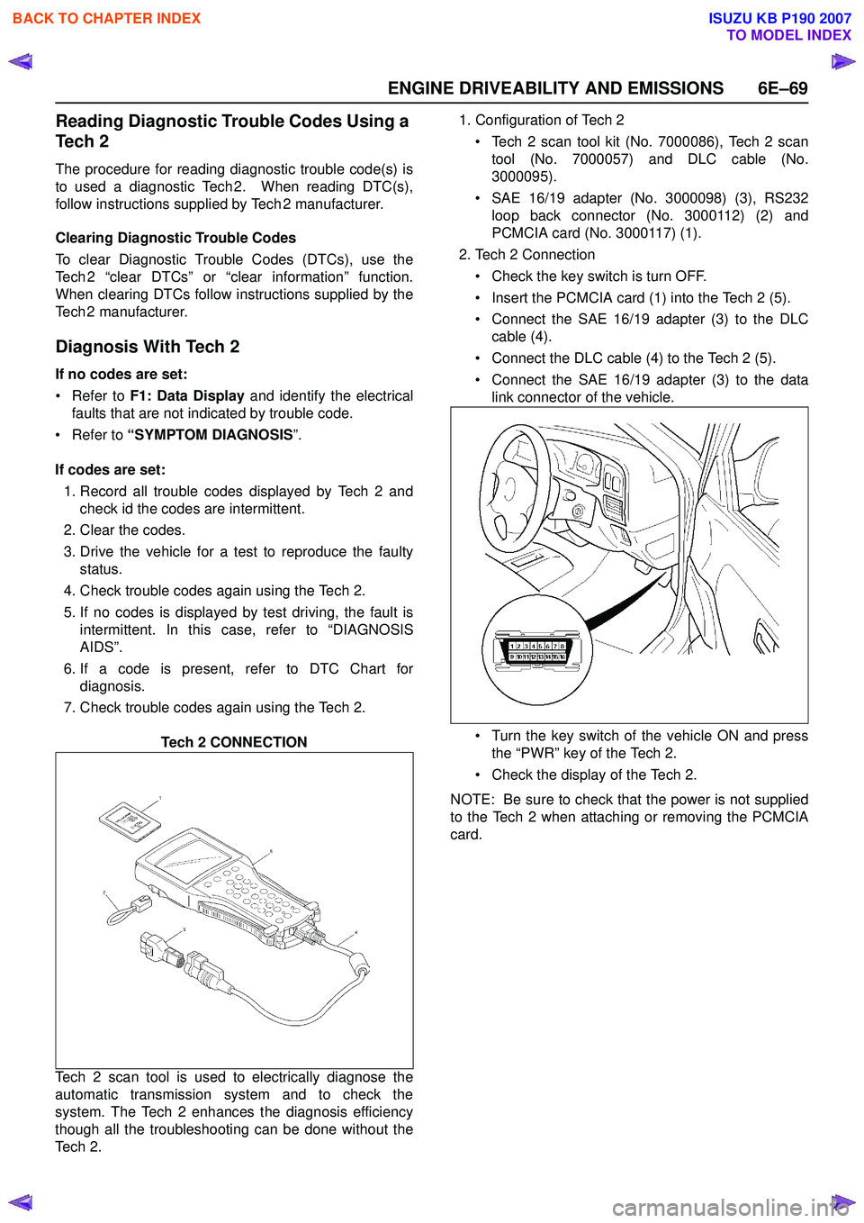
Tech 2 CONNECTION
Tech 2 scan tool is used to electrically diagnose the
automatic transmission system and to check the
system. The Tech 2 enhances the diagnosis efficiency
though all the troubleshooting can be done without the
Te c h 2 . 1. Configuration of Tech 2
• Tech 2 scan tool kit (No. 7000086), Tech 2 scan tool (No. 7000057) and DLC cable (No.
3000095).
• SAE 16/19 adapter (No. 3000098) (3), RS232 loop back connector (No. 3000112) (2) and
PCMCIA card (No. 3000117) (1).
2. Tech 2 Connection
• Check the key switch is turn OFF.
• Insert the PCMCIA card (1) into the Tech 2 (5).
• Connect the SAE 16/19 adapter (3) to the DLC cable (4).
• Connect the DLC cable (4) to the Tech 2 (5).
• Connect the SAE 16/19 adapter (3) to the data link connector of the vehicle.
• Turn the key switch of the vehicle ON and press the “PWR” key of the Tech 2.
• Check the display of the Tech 2.
NOTE: Be sure to check that the power is not supplied
to the Tech 2 when attaching or removing the PCMCIA
card.
BACK TO CHAPTER INDEX
TO MODEL INDEX
ISUZU KB P190 2007