Page 2396 of 6020

6E–226 ENGINE DRIVEABILITY AND EMISSIONS
DIAGNOSTIC TROUBLE CODE (DTC) P1649
IMMOBILIZER FUNCTION NOT PROGRAMMED
Condition for setting the DTC and action taken when the DTC sets
Circuit Description
The ECM decides whether that is an abnomality in the
immobilizer control system. DTC P1649 is recorded by
the ECM when security code & secret key not
programmed.
Diagnostic Aids
Check for the following conditions:
• Poor connection at ECM and Immobilizer-Inspect harness connectors for backed out terminals, improper mating, broken locks, improperly formed or
damaged terminals, and poor terminal to wire
connection.
• Damaged harness Inspect the wiring harness for damage, If the harness appears to be OK, disconnect
the ECM and Immobilizer, turn the ignition “ON” and
observe a voltmeter connected to the suspect driver
circuit at the ECM and Immobilizer harnass connector
while moving connectors and wiring harnesses
relates to the MIL. A change in voltage will indicate
the location of the fault.
Code Type DTC Name DTC Setting Condition Fail-Safe (Back Up)
P1649 - Immobilizer Function Not Programmed Immobilizer function is not programmed in the ECM.1. Engine does not start.
2. Check engine lamp flash.
BACK TO CHAPTER INDEX
TO MODEL INDEX
ISUZU KB P190 2007
Page 2431 of 6020

ENGINE DRIVEABILITY AND EMISSIONS 6E–261
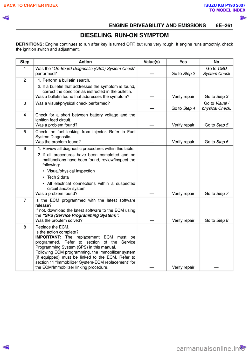
DIESELING, RUN-ON SYMPTOM
DEFINITIONS: Engine continues to run after key is turned OFF, but runs very rough. If engine runs smoothly, check
the ignition switch and adjustment.
Step Action Value(s) Yes No
1 Was the “ On-Board Diagnostic (OBD) System Check ”
performed? — Go to Step 2Go to
OBD
System Check
2 1. Perform a bulletin search. 2. If a bulletin that addresses the symptom is found,correct the condition as instructed in the bulletin.
Was a bulletin found that addresses the symptom? — Verify repair Go to Step 3
3 Was a visual/physical check performed? —Go to Step 4Go to
Visual /
physical Check .
4 Check for a short between battery voltage and the ignition feed circuit.
Was a problem found? — Verify repair Go to Step 5
5 Check the fuel leaking from injector. Refer to Fuel System Diagnostic.
Was the problem found? — Verify repair Go to Step 6
6 1. Review all diagnostic procedures within this table. 2. If all procedures have been completed and nomalfunctions have been found, review/inspect the
following:
• Visual/physical inspection
• Tech 2 data
• All electrical connections within a suspected circuit and/or system
Was a problem found? — Verify repair Go to Step 7
7 Is the ECM programmed with the latest software release?
If not, download the latest software to the ECM using
the “SPS (Service Programming System)”.
Was the problem solved? — Verify repair Go to Step 8
8 Replace the ECM. Is the action complete?
IMPORTANT: The replacement ECM must be
programmed. Refer to section of the Service
Programming System (SPS) in this manual.
Following ECM programming, the immobilizer system
(if equipped) must be linked to the ECM. Refer to
section 11 “Immobilizer System-ECM replacement” for
the ECM/Immobilizer linking procedure. — Verify repair —
BACK TO CHAPTER INDEX
TO MODEL INDEX
ISUZU KB P190 2007
Page 2494 of 6020
Engine Mechanical – V6 Page 6A1–15
Cylinder Head Assembly
Figure 6A1 – 7
Legend
1 Cylinder Head, Left-hand
2 Cylinder Head, Right-hand
3 Cylinder Head Gasket, Left-hand
4 Cylinder Head Gasket, Right-hand
5 Cylinder Head Bolt
6 Cylinder Head Front Bolt
7 Cylinder Head Coolant Hole Threaded Plug
8 Spark Plug Sleeve
9 Cylinder Head Oil Gallery Expansion Plug
10 Exhaust Valve
11 Intake Valve
12 Valve Rocker Arm Assembly
13 Hydraulic Valve Lash Adjuster Assembly
14 Valve Stem Oil Seal 15 Valve Spring
16 Valve Spring Cap
17 Valve Stem Key
18 Cylinder Head Camshaft Front Thrust Bearing Cap
19 Camshaft Oil Seal Ring
20 Exhaust Camshaft
21 Intake Camshaft, Left-hand (bank 2)
22 Intake Camshaft, Right-hand (bank 1)
23 Exhaust Camshaft, Right-hand (bank 1)
24 Cylinder Head Camshaft Cap – Intermediate
25 Cylinder Head Camshaft Cap Bolt
26 Cylinder Head Oil Galley Check Valve
27 Engine Coolant Temperature Sensor
BACK TO CHAPTER INDEX
TO MODEL INDEX
ISUZU KB P190 2007
Page 2543 of 6020

Engine Mechanical – V6 Page 6A1–64
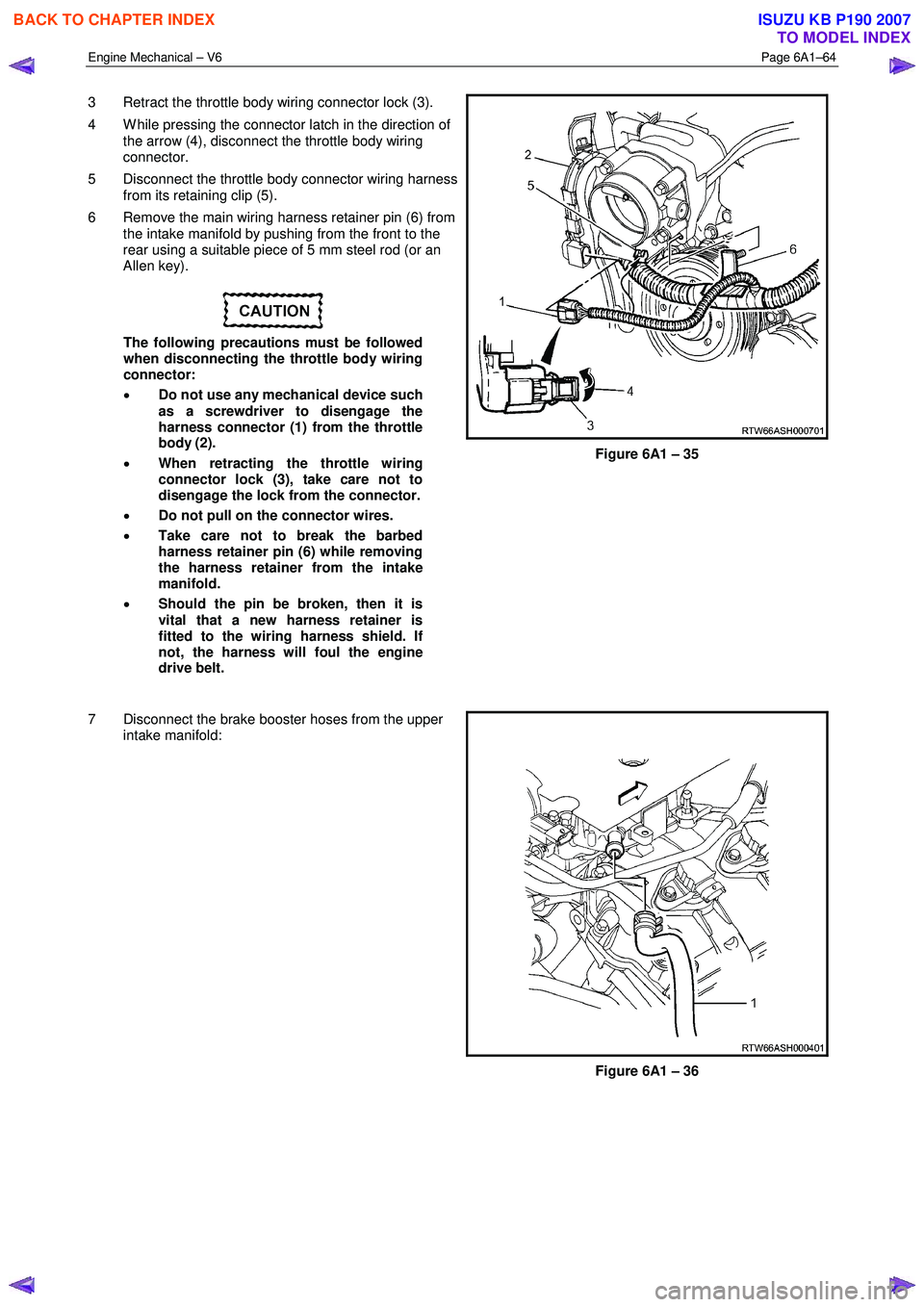
3 Retract the throttle body wiring connector lock (3).
4 W hile pressing the connector latch in the direction of the arrow (4), disconnect the throttle body wiring
connector.
5 Disconnect the throttle body connector wiring harness from its retaining clip (5).
6 Remove the main wiring harness retainer pin (6) from the intake manifold by pushing from the front to the
rear using a suitable piece of 5 mm steel rod (or an
Allen key).
The following precautions must be followed
when disconnecting the throttle body wiring
connector:
• Do not use any mechanical device such
as a screwdriver to disengage the
harness connector (1) from the throttle
body (2).
• When retracting the throttle wiring
connector lock (3), take care not to
disengage the lock from the connector.
• Do not pull on the connector wires.
• Take care not to break the barbed
harness retainer pin (6) while removing
the harness retainer from the intake
manifold.
• Should the pin be broken, then it is
vital that a new harness retainer is
fitted to the wiring harness shield. If
not, the harness will foul the engine
drive belt.
Figure 6A1 – 35
7 Disconnect the brake booster hoses from the upper intake manifold:
Figure 6A1 – 36
BACK TO CHAPTER INDEX
TO MODEL INDEX
ISUZU KB P190 2007
Page 2548 of 6020

Engine Mechanical – V6 Page 6A1–69
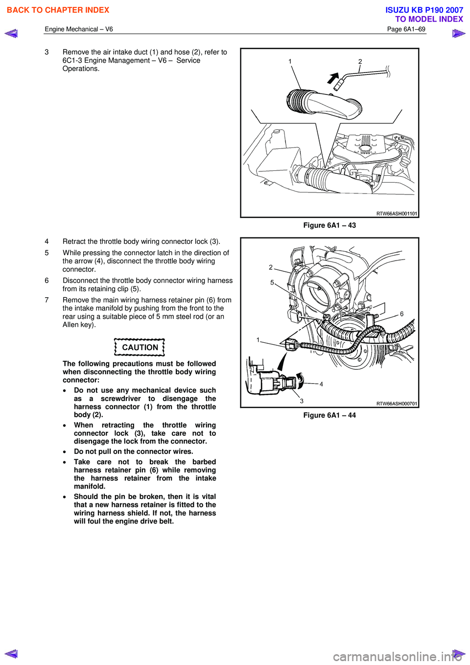
3 Remove the air intake duct (1) and hose (2), refer to
6C1-3 Engine Management – V6 – Service
Operations.
Figure 6A1 – 43
4 Retract the throttle body wiring connector lock (3).
5 W hile pressing the connector latch in the direction of the arrow (4), disconnect the throttle body wiring
connector.
6 Disconnect the throttle body connector wiring harness from its retaining clip (5).
7 Remove the main wiring harness retainer pin (6) from the intake manifold by pushing from the front to the
rear using a suitable piece of 5 mm steel rod (or an
Allen key).
The following precautions must be followed
when disconnecting the throttle body wiring
connector:
• Do not use any mechanical device such
as a screwdriver to disengage the
harness connector (1) from the throttle
body (2).
• When retracting the throttle wiring
connector lock (3), take care not to
disengage the lock from the connector.
• Do not pull on the connector wires.
• Take care not to break the barbed
harness retainer pin (6) while removing
the harness retainer from the intake
manifold.
• Should the pin be broken, then it is vital
that a new harness retainer is fitted to the
wiring harness shield. If not, the harness
will foul the engine drive belt.
Figure 6A1 – 44
BACK TO CHAPTER INDEX
TO MODEL INDEX
ISUZU KB P190 2007
Page 2586 of 6020

Engine Mechanical – V6 Page 6A1–107
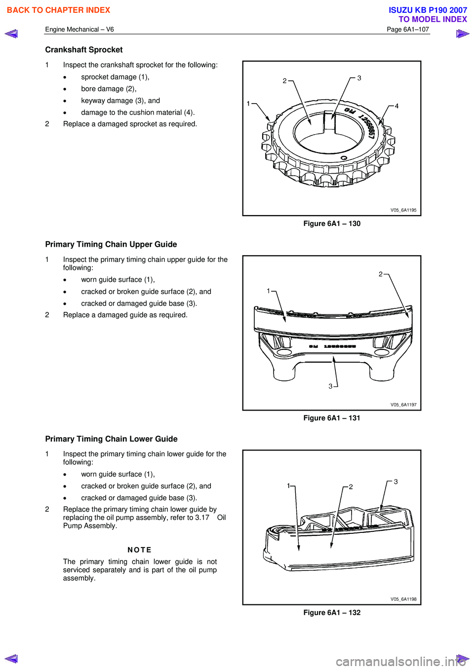
Crankshaft Sprocket
1 Inspect the crankshaft sprocket for the following:
• sprocket damage (1),
• bore damage (2),
• keyway damage (3), and
• damage to the cushion material (4).
2 Replace a damaged sprocket as required.
Figure 6A1 – 130
Primary Timing Chain Upper Guide
1 Inspect the primary timing chain upper guide for the following:
• worn guide surface (1),
• cracked or broken guide surface (2), and
• cracked or damaged guide base (3).
2 Replace a damaged guide as required.
Figure 6A1 – 131
Primary Timing Chain Lower Guide
1 Inspect the primary timing chain lower guide for the following:
• worn guide surface (1),
• cracked or broken guide surface (2), and
• cracked or damaged guide base (3).
2 Replace the primary timing chain lower guide by replacing the oil pump assembly, refer to 3.17 Oil
Pump Assembly.
NOTE
The primary timing chain lower guide is not
serviced separately and is part of the oil pump
assembly.
Figure 6A1 – 132
BACK TO CHAPTER INDEX
TO MODEL INDEX
ISUZU KB P190 2007
Page 2591 of 6020
Engine Mechanical – V6 Page 6A1–112
1 Install the crankshaft sprocket (1) onto the
crankshaft (2) by aligning the keyway to the key on
the crankshaft.
2 Slide the crankshaft sprocket on the crankshaft until the crankshaft sprocket contacts the step in the
crankshaft.
Figure 6A1 – 142
NOTE
Ensure that the crankshaft sprocket is installed
with the timing mark (1) visible.
Figure 6A1 – 143
CAUTION
In order to install Tool No. EN 46105 onto the
camshafts, rotate the camshafts in an anti-
clockwise direction. There should be no
need to rotate the camshaft more than 45
degrees.
Figure 6A1 – 144
BACK TO CHAPTER INDEX
TO MODEL INDEX
ISUZU KB P190 2007
Page 2643 of 6020
Engine Mechanical – V6 Page 6A1–164
CAUTION
Do not compress the valve springs less than
24.0 mm. Contact between the valve spring
retainer and the valve stem oil seal can
cause potential valve stem oil seal damage.
Compressed valve springs (1) have high
tension against the valve spring
compressor (2). Valve springs that are not
correctly compressed by, or are released
from the valve spring compressor can be
ejected from the valve spring compressor
with intense force. Use care when
compressing or releasing the valve spring
with the valve spring compressor and when
removing or installing the valve stem keys.
Failing to use care may cause personal
injury.
2 Compress the valve spring (1) using valve spring compressor Tool No. J-8062 (2) and adaptor Tool No.
EN-46119.
Figure 6A1 – 280
3 Remove the valve collets using Tool EN-46117 (1).
4 Remove the valve spring compressor (2) and the adapter (3).
Figure 6A1 – 281
BACK TO CHAPTER INDEX
TO MODEL INDEX
ISUZU KB P190 2007