2007 ISUZU KB P190 key
[x] Cancel search: keyPage 3736 of 6020
Powertrain Interface Module – V6 Page 6E1–75
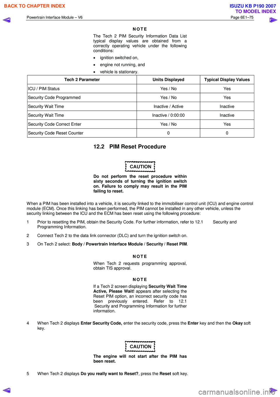
NOTE
The Tech 2 PIM Security Information Data List
typical display values are obtained from a
correctly operating vehicle under the following
conditions:
• ignition switched on,
• engine not running, and
• vehicle is stationary.
Tech 2 Parameter Units Displayed Typical Display Values
ICU / PIM Status Yes / No Yes
Security Code Programmed Yes / No Yes
Security W ait Time Inactive / Active Inactive
Security W ait Time Inactive / 0:00:00 Inactive
Security Code Correct Enter Yes / No Yes
Security Code Reset Counter 0 0
12.2 PIM Reset Procedure
Do not perform the reset procedure within
sixty seconds of turning the ignition switch
on. Failure to comply may result in the PIM
failing to reset.
W hen a PIM has been installed into a vehicle, it is security linked to the immobiliser control unit (ICU) and engine control
module (ECM). Once this linking has been performed, the PIM cannot be installed in any other vehicle, unless the
security linking between the ICU and the ECM has been reset using the following procedure:
1 Prior to resetting the PIM, obtain the Security Code. For further information, refer to 12.1 Security and Programming Information.
2 Connect Tech 2 to the data link connector (DLC) and turn the ignition switch on.
3 On Tech 2 select: Body / Powertrain Interface Module / Security / Reset PIM .
NOTE
When Tech 2 requests programming approval,
obtain TIS approval.
NOTE
If a Tech 2 screen displaying Security Wait Time
Active, Please Wait! appears after selecting the
Reset PIM option, an incorrect security code has
been previously entered. Refer to 12.1
Security and Programming Information for further
information.
4 W hen Tech 2 displays Enter Security Code, enter the security code, press the Enter key and then the Okay soft
key.
The engine will not start after the PIM has
been reset.
5 W hen Tech 2 displays Do you really want to Reset? , press the Reset soft key.
BACK TO CHAPTER INDEX
TO MODEL INDEX
ISUZU KB P190 2007
Page 3737 of 6020
Powertrain Interface Module – V6 Page 6E1–76
Do not turn the ignition switch off within 60
seconds of performing the PIM reset
procedure. Failure to comply may result in the
PIM failing to reset.
6 W hen Tech 2 displays Reset Completed Successfully , press the Confirm soft key to return to the Tech 2
Security screen.
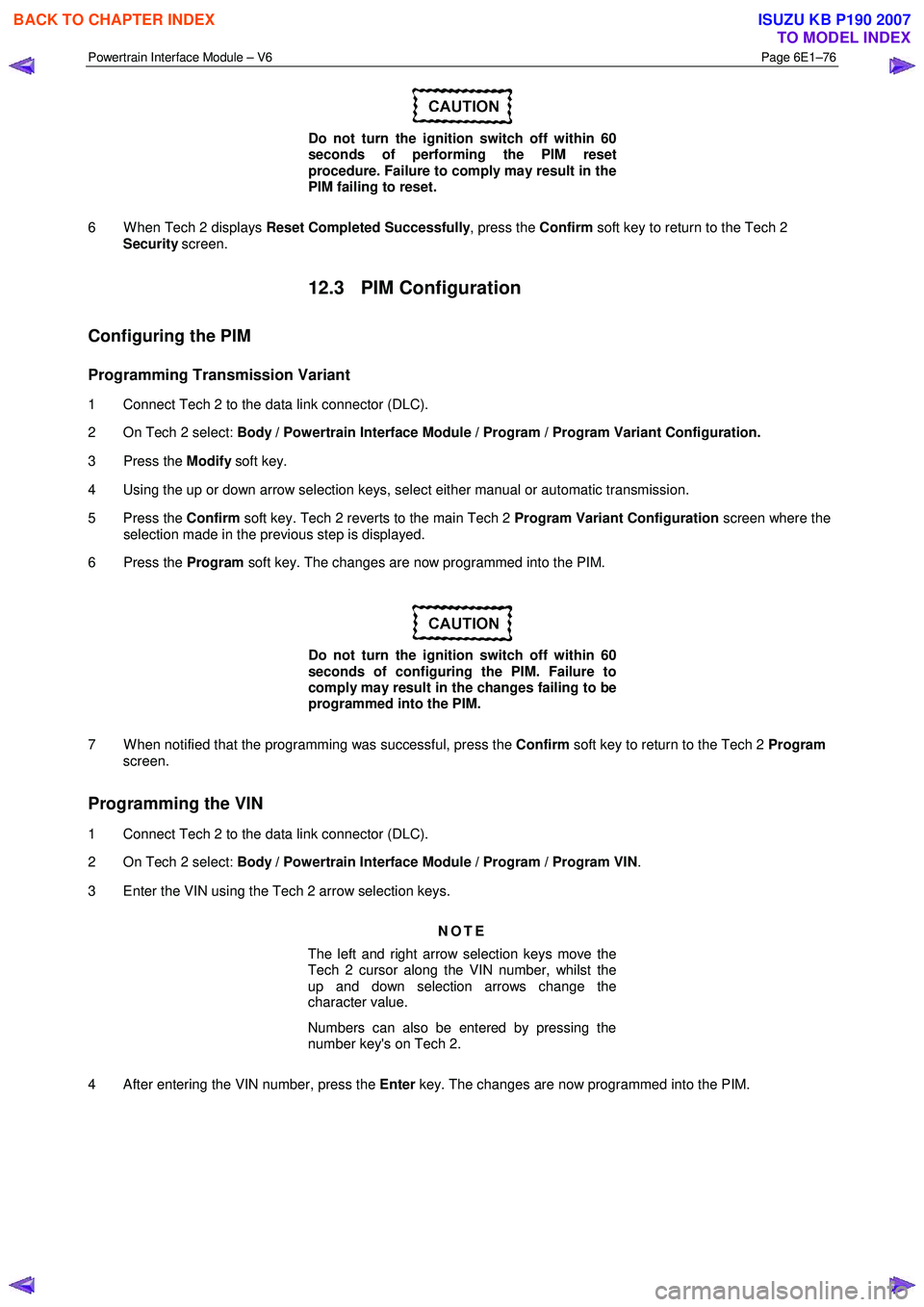
12.3 PIM Configuration
Configuring the PIM
Programming Transmission Variant
1 Connect Tech 2 to the data link connector (DLC).
2 On Tech 2 select: Body / Powertrain Interface Module / Program / Program Variant Configuration.
3 Press the Modify soft key.
4 Using the up or down arrow selection keys, select either manual or automatic transmission.
5 Press the Confirm soft key. Tech 2 reverts to the main Tech 2 Program Variant Configuration screen where the
selection made in the previous step is displayed.
6 Press the Program soft key. The changes are now programmed into the PIM.
Do not turn the ignition switch off within 60
seconds of configuring the PIM. Failure to
comply may result in the changes failing to be
programmed into the PIM.
7 W hen notified that the programming was successful, press the Confirm soft key to return to the Tech 2 Program
screen.
Programming the VIN
1 Connect Tech 2 to the data link connector (DLC).
2 On Tech 2 select: Body / Powertrain Interface Module / Program / Program VIN .
3 Enter the VIN using the Tech 2 arrow selection keys.
NOTE
The left and right arrow selection keys move the
Tech 2 cursor along the VIN number, whilst the
up and down selection arrows change the
character value.
Numbers can also be entered by pressing the
number key's on Tech 2.
4 After entering the VIN number, press the Enter key. The changes are now programmed into the PIM.
BACK TO CHAPTER INDEX
TO MODEL INDEX
ISUZU KB P190 2007
Page 3738 of 6020
Powertrain Interface Module – V6 Page 6E1–77
Do not turn the ignition switch off within 60
seconds of programming the VIN. Failure to
comply may result in the changes failing to be
programmed into the PIM.
5 W hen notified that the programming was successful, press the Confirm soft key to return to the Tech 2 Program
screen.
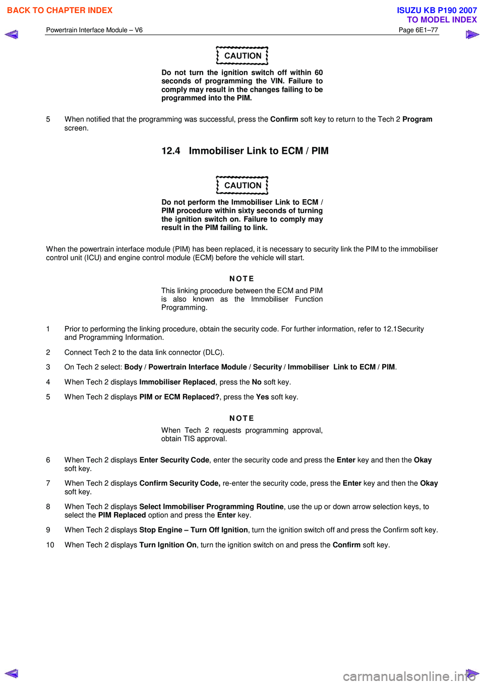
12.4 Immobiliser Link to ECM / PIM
Do not perform the Immobiliser Link to ECM /
PIM procedure within sixty seconds of turning
the ignition switch on. Failure to comply may
result in the PIM failing to link.
W hen the powertrain interface module (PIM) has been replaced, it is necessary to security link the PIM to the immobiliser
control unit (ICU) and engine control module (ECM) before the vehicle will start.
NOTE
This linking procedure between the ECM and PIM
is also known as the Immobiliser Function
Programming.
1 Prior to performing the linking procedure, obtain the security code. For further information, refer to 12.1Security and Programming Information.
2 Connect Tech 2 to the data link connector (DLC).
3 On Tech 2 select: Body / Powertrain Interface Module / Security / Immobiliser Link to ECM / PIM .
4 W hen Tech 2 displays Immobiliser Replaced, press the No soft key.
5 W hen Tech 2 displays PIM or ECM Replaced?, press the Yes soft key.
NOTE
When Tech 2 requests programming approval,
obtain TIS approval.
6 W hen Tech 2 displays Enter Security Code, enter the security code and press the Enter key and then the Okay
soft key.
7 W hen Tech 2 displays Confirm Security Code, re-enter the security code, press the Enter key and then the Okay
soft key.
8 W hen Tech 2 displays Select Immobiliser Programming Routine , use the up or down arrow selection keys, to
select the PIM Replaced option and press the Enter key.
9 W hen Tech 2 displays Stop Engine – Turn Off Ignition , turn the ignition switch off and press the Confirm soft key.
10 W hen Tech 2 displays Turn Ignition On, turn the ignition switch on and press the Confirm soft key.
BACK TO CHAPTER INDEX
TO MODEL INDEX
ISUZU KB P190 2007
Page 3739 of 6020

Powertrain Interface Module – V6 Page 6E1–78
Do not turn the ignition switch off within 60
seconds of performing the ICU Link to
ECM / PIM procedure. Failure to comply may
result in the PIM failing to link with the
ICU / ECM.
11 W hen Tech 2 displays Programming Successful, press the Confirm soft key to return to the Tech 2 Security
screen.
BACK TO CHAPTER INDEX
TO MODEL INDEX
ISUZU KB P190 2007
Page 3744 of 6020
Powertrain Interface Module – V6 Page 6E1–83
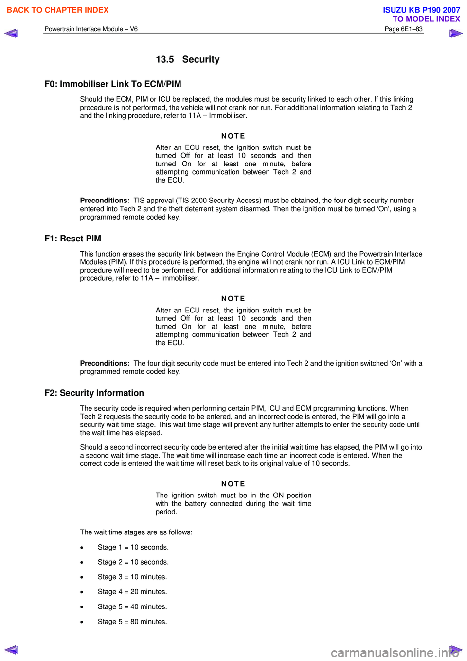
13.5 Security
F0: Immobiliser Link To ECM/PIM
Should the ECM, PIM or ICU be replaced, the modules must be security linked to each other. If this linking
procedure is not performed, the vehicle will not crank nor run. For additional information relating to Tech 2
and the linking procedure, refer to 11A – Immobiliser.
NOTE
After an ECU reset, the ignition switch must be
turned Off for at least 10 seconds and then
turned On for at least one minute, before
attempting communication between Tech 2 and
the ECU.
Preconditions: TIS approval (TIS 2000 Security Access) must be obtained, the four digit security number
entered into Tech 2 and the theft deterrent system disarmed. Then the ignition must be turned ‘On’, using a
programmed remote coded key.
F1: Reset PIM
This function erases the security link between the Engine Control Module (ECM) and the Powertrain Interface Modules (PIM). If this procedure is performed, the engine will not crank nor run. A ICU Link to ECM/PIM
procedure will need to be performed. For additional information relating to the ICU Link to ECM/PIM
procedure, refer to 11A – Immobiliser.
NOTE
After an ECU reset, the ignition switch must be
turned Off for at least 10 seconds and then
turned On for at least one minute, before
attempting communication between Tech 2 and
the ECU.
Preconditions: The four digit security code must be entered into Tech 2 and the ignition switched ‘On’ with a
programmed remote coded key.
F2: Security Information
The security code is required when performing certain PIM, ICU and ECM programming functions. W hen Tech 2 requests the security code to be entered, and an incorrect code is entered, the PIM will go into a
security wait time stage. This wait time stage will prevent any further attempts to enter the security code until
the wait time has elapsed.
Should a second incorrect security code be entered after the initial wait time has elapsed, the PIM will go into a second wait time stage. The wait time will increase each time an incorrect code is entered. W hen the
correct code is entered the wait time will reset back to its original value of 10 seconds.
NOTE
The ignition switch must be in the ON position
with the battery connected during the wait time
period.
The wait time stages are as follows: • Stage 1 = 10 seconds.
• Stage 2 = 10 seconds.
• Stage 3 = 10 minutes.
• Stage 4 = 20 minutes.
• Stage 5 = 40 minutes.
• Stage 5 = 80 minutes.
BACK TO CHAPTER INDEX
TO MODEL INDEX
ISUZU KB P190 2007
Page 3802 of 6020
Automatic Transmission – 4L60E – Electrical Diagnosis Page 7C2–16
Programming
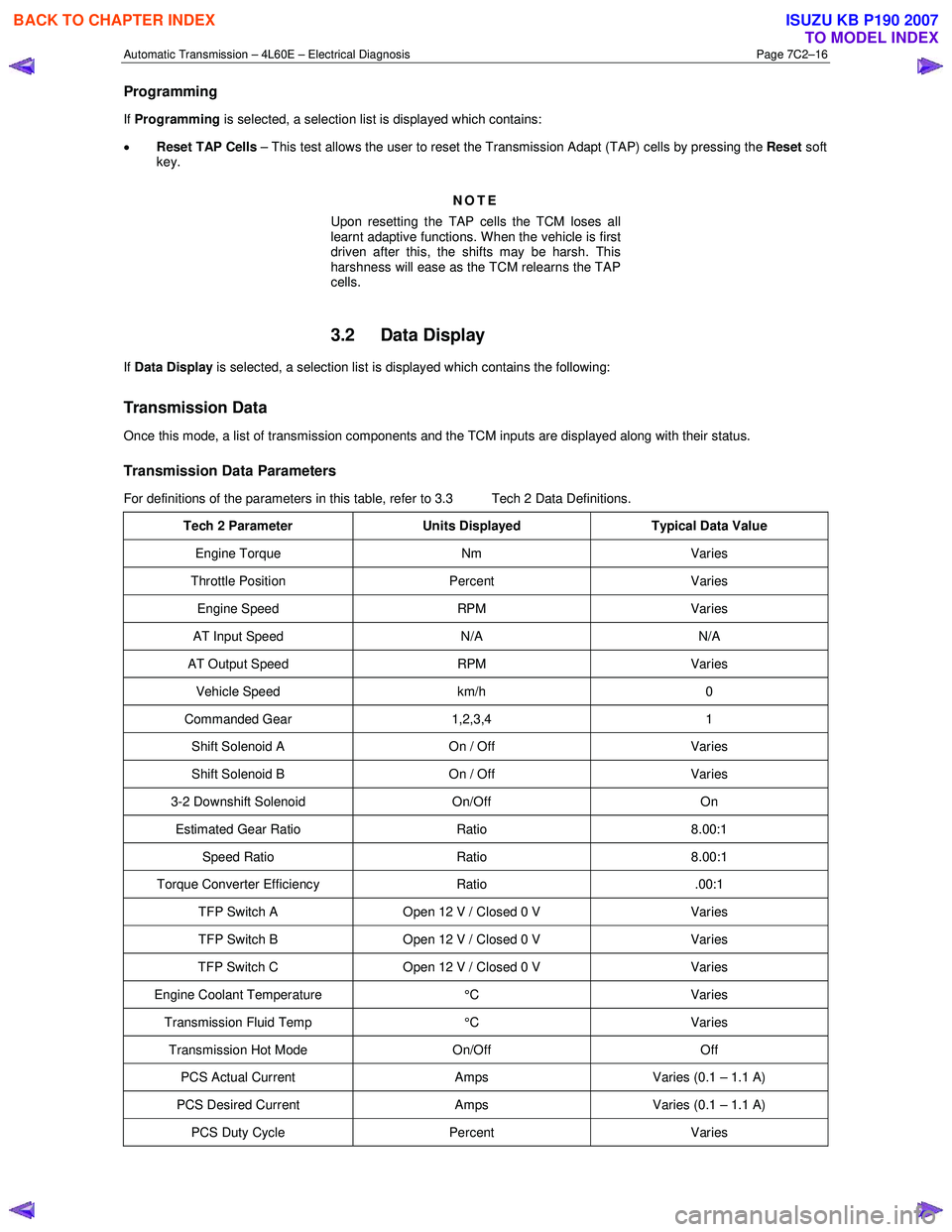
If Programming is selected, a selection list is displayed which contains:
• Reset TAP Cells – This test allows the user to reset the Transmission Adapt (TAP) cells by pressing the Reset soft
key.
NOTE
Upon resetting the TAP cells the TCM loses all
learnt adaptive functions. When the vehicle is first
driven after this, the shifts may be harsh. This
harshness will ease as the TCM relearns the TAP
cells.
3.2 Data Display
If Data Display is selected, a selection list is displayed which contains the following:
Transmission Data
Once this mode, a list of transmission components and the TCM inputs are displayed along with their status.
Transmission Data Parameters
For definitions of the parameters in this table, refer to 3.3 Tech 2 Data Definitions.
Tech 2 Parameter Units Displayed Typical Data Value
Engine Torque Nm Varies
Throttle Position Percent Varies
Engine Speed RPM Varies
AT Input Speed N/A N/A
AT Output Speed RPM Varies
Vehicle Speed km/h 0
Commanded Gear 1,2,3,4 1
Shift Solenoid A On / Off Varies
Shift Solenoid B On / Off Varies
3-2 Downshift Solenoid On/Off On
Estimated Gear Ratio Ratio 8.00:1
Speed Ratio Ratio 8.00:1
Torque Converter Efficiency Ratio .00:1
TFP Switch A Open 12 V / Closed 0 V Varies
TFP Switch B Open 12 V / Closed 0 V Varies
TFP Switch C Open 12 V / Closed 0 V Varies
Engine Coolant Temperature °C Varies
Transmission Fluid Temp °C Varies
Transmission Hot Mode On/Off Off
PCS Actual Current Amps Varies (0.1 – 1.1 A)
PCS Desired Current Amps Varies (0.1 – 1.1 A)
PCS Duty Cycle Percent Varies
BACK TO CHAPTER INDEX
TO MODEL INDEX
ISUZU KB P190 2007
Page 3836 of 6020
Automatic Transmission – 4L60E – Electrical Diagnosis Page 7C2–50
Action Taken When the DTC Sets
• The TCM illuminates the MIL during the second consecutive trip in which the Conditions for Setting the DTC are
met.
• The TCM commands maximum line pressure.
• The TCM freezes transmission adaptive functions.
• The TCM calculates vehicle speed from the automatic transmission engine r.p.m. and commanded gear.
• At the time of the first failure, the TCM records the operating conditions when the conditions for setting the DTC are
met. The TCM stores this information as a Failure Record.
• At the time of the second failure, the ECM records the operating conditions when the conditions for setting the DTC
are met. The ECM stores this information as a Freeze Frame.
• The TCM stores DTC P0722 in TCM history.
Conditions for Clearing the DTC
• The ECM turns off the MIL after the sixth consecutive drive trip in which the TCM does not send a MIL illumination
request.
• Tech 2 can clear the DTC.
• The TCM clears the DTC from TCM history if the vehicle completes 40 warm-up cycles without an emission related
diagnostic fault occurring.
• The TCM cancels the default actions when the ignition is off long enough to power down the TCM.
Diagnostic Aids
• Inspect the rear internal gear teeth for damage.
• Visually inspect the VSS for cracks or damage.
• Ensure the VSS is properly torqued to the extension housing.
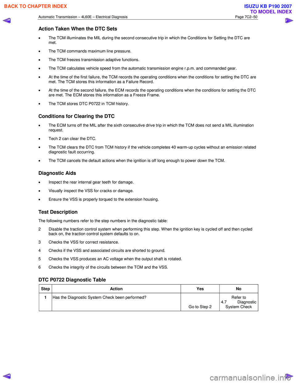
Test Description
The following numbers refer to the step numbers in the diagnostic table:
2 Disable the traction control system when performing this step. W hen the ignition key is cycled off and then cycled back on, the traction control system defaults to on.
3 Checks the VSS for correct resistance.
4 Checks if the VSS and associated circuits are shorted to ground.
5 Checks the VSS produces an AC voltage when the output shaft is rotated.
6 Checks the integrity of the circuits between the TCM and the VSS.
DTC P0722 Diagnostic Table
Step Action Yes No
1 Has the Diagnostic System Check been performed?
Go to Step 2 Refer to
4.7 Diagnostic System Check
BACK TO CHAPTER INDEX
TO MODEL INDEX
ISUZU KB P190 2007
Page 3839 of 6020
Automatic Transmission – 4L60E – Electrical Diagnosis Page 7C2–53
• Ignition voltage is 8 – 18 V.
• TFT is -40°C and 150°C.
• The engine run time is greater than 5 seconds.
• The throttle position is greater than 12 percent.
• The engine torque is 108 – 882 Nm.
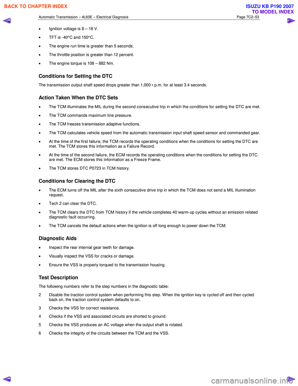
Conditions for Setting the DTC
The transmission output shaft speed drops greater than 1,000 r.p.m. for at least 3.4 seconds.
Action Taken When the DTC Sets
• The TCM illuminates the MIL during the second consecutive trip in which the conditions for setting the DTC are met.
• The TCM commands maximum line pressure.
• The TCM freezes transmission adaptive functions.
• The TCM calculates vehicle speed from the automatic transmission input shaft speed sensor and commanded gear.
• At the time of the first failure, the TCM records the operating conditions when the conditions for setting the DTC are
met. The TCM stores this information as a Failure Record.
• At the time of the second failure, the ECM records the operating conditions when the conditions for setting the DTC
are met. The ECM stores this information as a Freeze Frame.
• The TCM stores DTC P0723 in TCM history.
Conditions for Clearing the DTC
• The ECM turns off the MIL after the sixth consecutive drive trip in which the TCM does not send a MIL illumination
request.
• Tech 2 can clear the DTC.
• The TCM clears the DTC from TCM history if the vehicle completes 40 warm-up cycles without an emission related
diagnostic fault occurring.
• The TCM cancels the default actions when the ignition is off long enough to power down the TCM.
Diagnostic Aids
•
Inspect the rear internal gear teeth for damage.
• Visually inspect the VSS for cracks or damage.
• Ensure the VSS is properly torqued to the transmission housing.
Test Description
The following numbers refer to the step numbers in the diagnostic table:
2 Disable the traction control system when performing this step. W hen the ignition key is cycled off and then cycled back on, the traction control system defaults to on.
3 Checks the VSS for correct resistance.
4 Checks if the VSS and associated circuits are shorted to ground.
5 Checks the VSS produces an AC voltage when the output shaft is rotated.
6 Checks the integrity of the circuits between the TCM and the VSS.
BACK TO CHAPTER INDEX
TO MODEL INDEX
ISUZU KB P190 2007