2007 ISUZU KB P190 key
[x] Cancel search: keyPage 4141 of 6020
7A4–6 UNIT REPAIR (AW30–40LE)
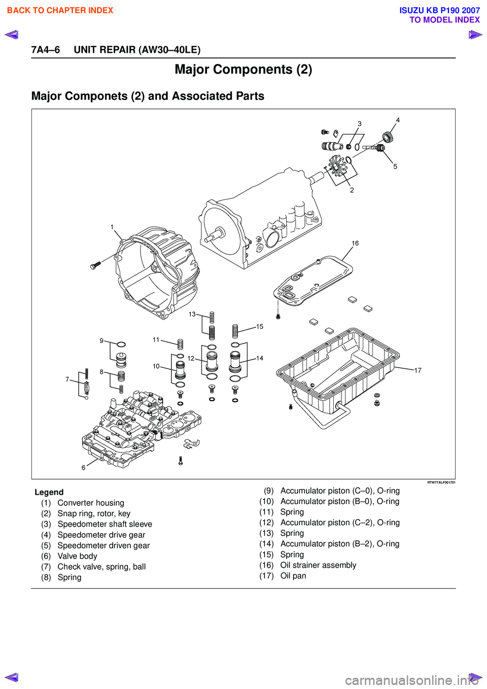
Major Components (2)
Major Componets (2) and Associated Parts
RTW77ALF001701
EndOFCallout
Legend(1) Converter housing
(2) Snap ring, rotor, key
(3) Speedometer shaft sleeve
(4) Speedometer drive gear
(5) Speedometer driven gear
(6) Valve body
(7) Check valve, spring, ball
(8) Spring (9) Accumulator piston (C
–0), O-ring
(10) Accumulator piston (B –0), O-ring
(11) Spring
(12) Accumulator piston (C –2), O-ring
(13) Spring
(14) Accumulator piston (B –2), O-ring
(15) Spring
(16) Oil strainer assembly
(17) Oil pan
BACK TO CHAPTER INDEX
TO MODEL INDEX
ISUZU KB P190 2007
Page 4144 of 6020
UNIT REPAIR (AW30–40LE) 7A4–9
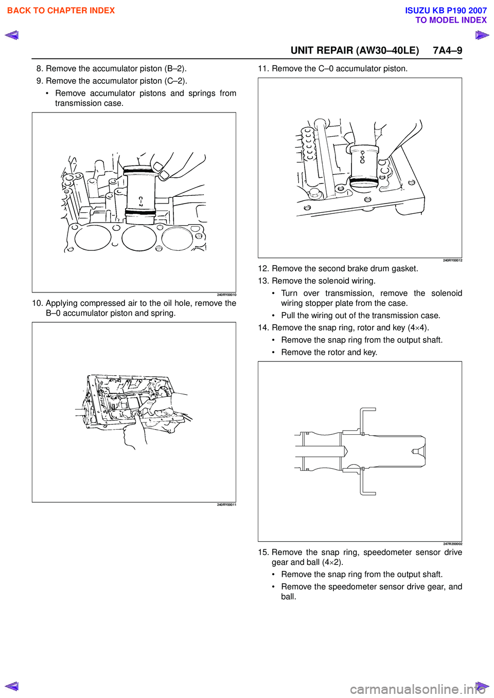
8. Remove the accumulator piston (B–2).
9. Remove the accumulator piston (C –2).
Remove accumulator pistons and springs from
transmission case.
240RY00010
10. Applying compressed air to the oil hole, remove the B–0 accumulator piston and spring.
240RY00011
11. Remove the C –0 accumulator piston.
240RY00012
12. Remove the second brake drum gasket.
13. Remove the solenoid wiring.
Turn over transmission, remove the solenoid
wiring stopper plate from the case.
Pull the wiring out of the transmission case.
14. Remove the snap ring, rotor and key (4 ×4).
Remove the snap ring from the output shaft.
Remove the rotor and key.
247R200002
15. Remove the snap ring, speedometer sensor drive
gear and ball (4 ×2).
Remove the snap ring from the output shaft.
Remove the speedometer sensor drive gear, and
ball.
BACK TO CHAPTER INDEX
TO MODEL INDEX
ISUZU KB P190 2007
Page 4145 of 6020
7A4–10 UNIT REPAIR (AW30–40LE)
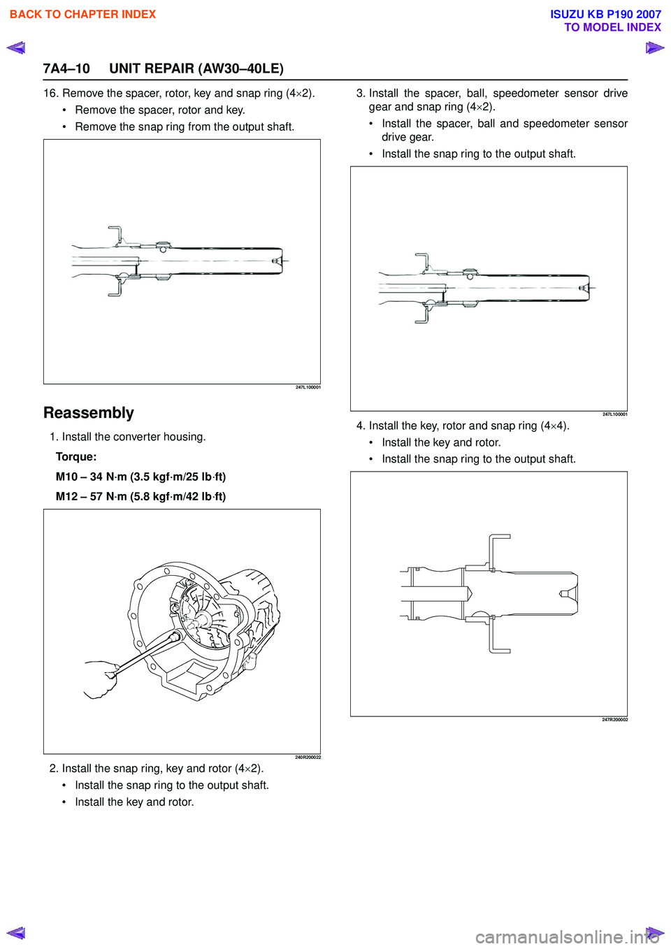
16. Remove the spacer, rotor, key and snap ring (4×2).
Remove the spacer, rotor and key.
Remove the snap ring from the output shaft.
247L100001
Reassembly
1. Install the converter housing.
Torque:
M10 – 34 N ·m (3.5 kgf ·m/25 lb ·ft)
M12 – 57 N ·m (5.8 kgf ·m/42 lb ·ft)
240R200022
2. Install the snap ring, key and rotor (4 ×2).
Install the snap ring to the output shaft.
Install the key and rotor. 3. Install the spacer, ball, speedometer sensor drive
gear and snap ring (4 ×2).
Install the spacer, ball and speedometer sensor
drive gear.
Install the snap ring to the output shaft.
247L100001
4. Install the key, rotor and snap ring (4 ×4).
Install the key and rotor.
Install the snap ring to the output shaft.
247R200002
BACK TO CHAPTER INDEX
TO MODEL INDEX
ISUZU KB P190 2007
Page 4285 of 6020

TRANSMISSION CONTROL SYSTEM (JR405E) 7A2-1
TRANSMISSION
TRANSMISSION CONTROL SYSTEM (JR405E)
This manual conforms when Scan Tool of ISO CAN Base Software is used.
TABLE OF CONTENTS
Specifications ...................................................... 7A2-2Transmission General Specifications ............... 7A2-2
Transmission Fluid Temperature vs. Resistance..... 7A2-3
Clutch, Brake, Solenoid and Pressure Switch Logic........ 7A2-4
Diagnostic Trouble Code (DTC) List ................ 7A2-5
Schematic and Routing Diagrams....................... 7A2-6 Transmission Controls Schematics .................. 7A2-6
Component Locator........................................... 7A2-13 Transmission Controls Component Views ..... 7A2-13
Transmission Control Module (TCM) Connector End Views ................................... 7A2-17
Transmission Control Connector End Views.. 7A2-18
Diagnostic Information and Procedures ............ 7A2-21
Diagnostic Starting Point - Transmission Controls......... 7A2-21
Diagnostic System Check - Transmission Controls....... 7A2-22
Scan Tool Data List ........................................ 7A2-24
Scan Tool Data Definitions............................. 7A2-25
Scan Tool Output Controls ............................. 7A2-27
Scan Tool Does Not Power Up ...................... 7A2-28
Scan Tool Does Not Communicate with Keyword Device .................................... 7A2-29
Lost Communication with The Transmission Control Module (TCM)
.... 7A2-31
DTC P0560 (Flash Code 16).......................... 7A2-33
DTC P0602 .................................................... 7A2-35
DTC P0705 (Flash Code 17).......................... 7A2-36
DTC P0710 (Flash Code 15).......................... 7A2-40
DTC P0717 (Flash Code 14).......................... 7A2-44
DTC P0722 (Flash Code 11).......................... 7A2-47
DTC P0727 (Flash Code 13).......................... 7A2-50
DTC P0731, P0732, P0733 or P0734 (Flash Code 41, 42, 43 or 44)....................... 7A2-52
DTC P0748 (Flash Code 35).......................... 7A2-55
DTC P0753 (Flash Code 31).......................... 7A2-58
DTC P0758 (Flash Code 32).......................... 7A2-61
DTC P0763 (Flash Code 33).......................... 7A2-64
DTC P0768 (Flash Code 34).......................... 7A2-67
DTC P1120 (Flash Code 22).......................... 7A2-70
DTC P1750 (Flash Code 51).......................... 7A2-71
DTC P1755 (Flash Code 52).......................... 7A2-73
DTC P1853 (Flash Code 26).......................... 7A2-75
DTC P1858 (Flash Code 27).......................... 7A2-78
DTC P1860 (Flash Code 36).......................... 7A2-81
DTC P1863 (Flash Code 28).......................... 7A2-84
DTC P1875 (Flash Code 25).......................... 7A2-87
Check Trans Lamp Inoperative, Always On or Always Blinking ...................... 7A2-89
Symptoms - Transmission Controls .................. 7A2-92 Symptoms - Transmission Controls ............... 7A2-92
Intermittent Conditions ................................... 7A2-93 Vehicle Does Not Run .................................... 7A2-95
Trouble at Starting.......................................... 7A2-95
Faulty Gearshift .............................................. 7A2-95
Faulty Shift Pattern......................................... 7A2-95
No or Error Gearshift ...................................... 7A2-95
Faulty Operation During Running................... 7A2-95
Faulty Operation in Stopping.......................... 7A2-95
Faulty Lock Up ............................................... 7A2-95
No Lock Up .................................................... 7A2-95
Transmission Fluid Leak ................................ 7A2-95
Others ............................................................ 7A2-95
Test Instructions .............................................. 7A2-121 Line Pressure Test ....................................... 7A2-121
Stall Test ...................................................... 7A2-123
Time Lag Test .............................................. 7A2-124
Road Test..................................................... 7A2-125
TCM Signal Test .......................................... 7A2-134
Repair Instructions .......................................... 7A2-139
Transmission Controls Module (TCM) Replacement.... 7A2-139
Service Programming System (SPS) Description........ 7A2-139
Service Programming System (SPS) (Remote Procedure)......................... 7A2-140
Service Programming System (SPS) (Pass-Thru Procedure)..................... 7A2-141
Description and Operation .............................. 7A2-143 Transmission Identification Information........ 7A2-143
Transmission General Description ............... 7A2-143
Transmission Component Description ......... 7A2-144
Transmission Control System Description ... 7A2-152
Transmission Power Flow Description ......... 7A2-161
Special Tools and Equipment ......................... 7A2-170 Special Tools and Equipment ...................... 7A2-170
BACK TO CHAPTER INDEX
TO MODEL INDEX
ISUZU KB P190 2007
Page 4301 of 6020
TRANSMISSION CONTROL SYSTEM (JR405E) 7A2-17
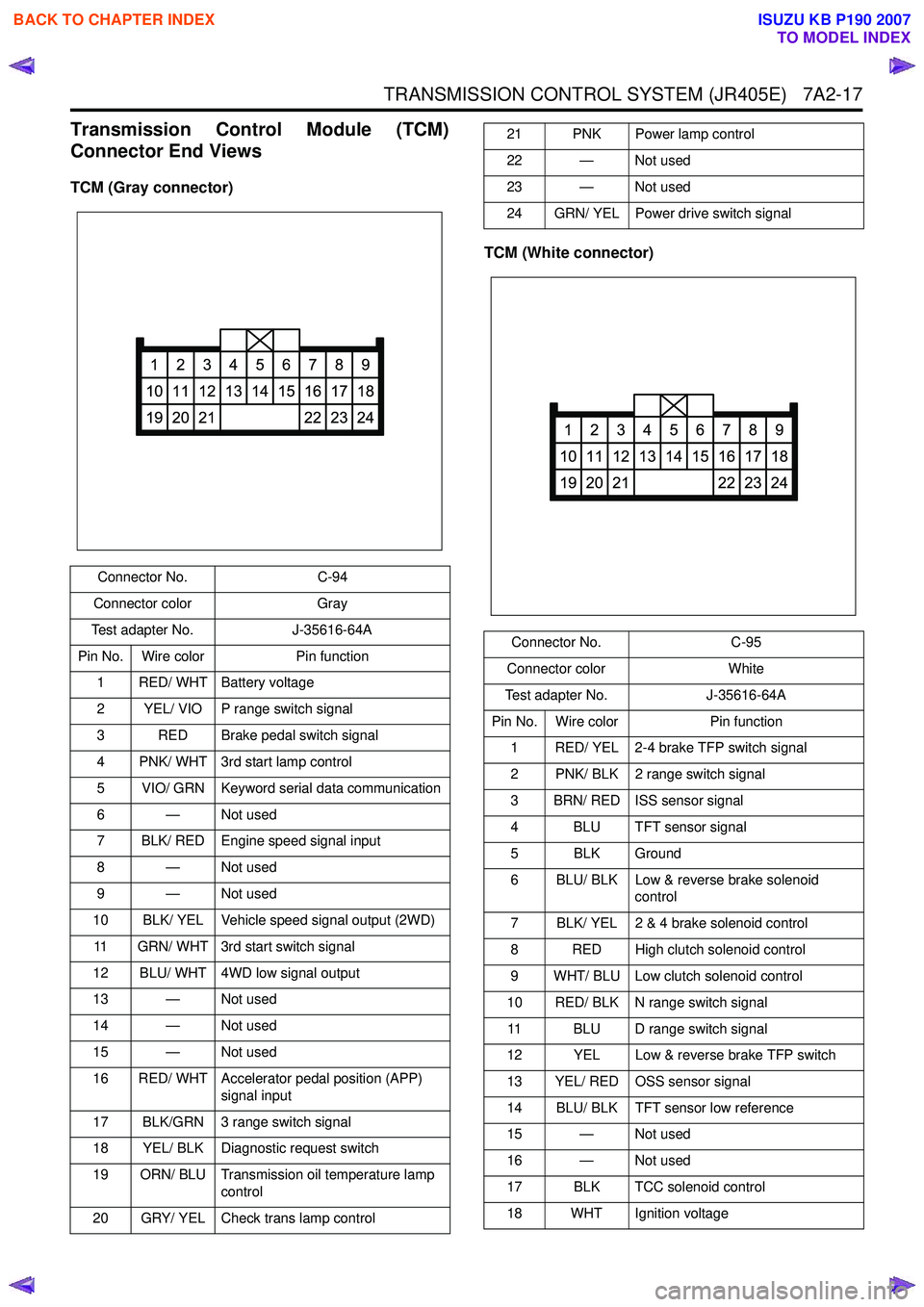
Transmission Control Module (TCM)
Connector End Views
TCM (Gray connector)
TCM (White connector)
Connector No.C-94
Connector color Gray
Test adapter No. J-35616-64A
Pin No. Wire color Pin function
1 RED/ WHT Battery voltage
2 YEL/ VIO P range switch signal
3 RED Brake pedal switch signal
4 PNK/ WHT 3rd start lamp control
5 VIO/ GRN Keyword serial data communication
6 — Not used
7 BLK/ RED Engine speed signal input
8 — Not used
9 — Not used
10 BLK/ YEL Vehicle speed signal output (2WD)
11 GRN/ WHT 3rd start switch signal
12 BLU/ WHT 4WD low signal output
13 — Not used
14 — Not used
15 — Not used
16 RED/ WHT Accelerator pedal position (APP) signal input
17 BLK/GRN 3 range switch signal
18 YEL/ BLK Diagnostic request switch
19 ORN/ BLU Transmission oil temperature lamp control
20 GRY/ YEL Check trans lamp control
1
10
19
2
11
20
3
12
21
4
13
5
14
6
15
7
16
22
8
17
23
9
18
24
21 PNK Power lamp control
22 — Not used
23 — Not used
24 GRN/ YEL Power drive switch signal
Connector No. C-95
Connector color White
Test adapter No. J-35616-64A
Pin No. Wire color Pin function
1 RED/ YEL 2-4 brake TFP switch signal
2 PNK/ BLK 2 range switch signal
3 BRN/ RED ISS sensor signal
4 BLU TFT sensor signal
5 BLK Ground
6 BLU/ BLK Low & reverse brake solenoid control
7 BLK/ YEL 2 & 4 brake solenoid control
8 RED High clutch solenoid control
9 WHT/ BLU Low clutch solenoid control
10 RED/ BLK N range switch signal 11 BLU D range switch signal
12 YEL Low & reverse brake TFP switch
13 YEL/ RED OSS sensor signal
14 BLU/ BLK TFT sensor low reference
15 — Not used
16 — Not used
17 BLK TCC solenoid control
18 WHT Ignition voltage
1
10
19
2
11
20
3
12
21
4
13
5
14
6
15
7
16
22
8
17
23
9
18
24
BACK TO CHAPTER INDEX
TO MODEL INDEX
ISUZU KB P190 2007
Page 4302 of 6020
7A2-18 TRANSMISSION CONTROL SYSTEM (JR405E)
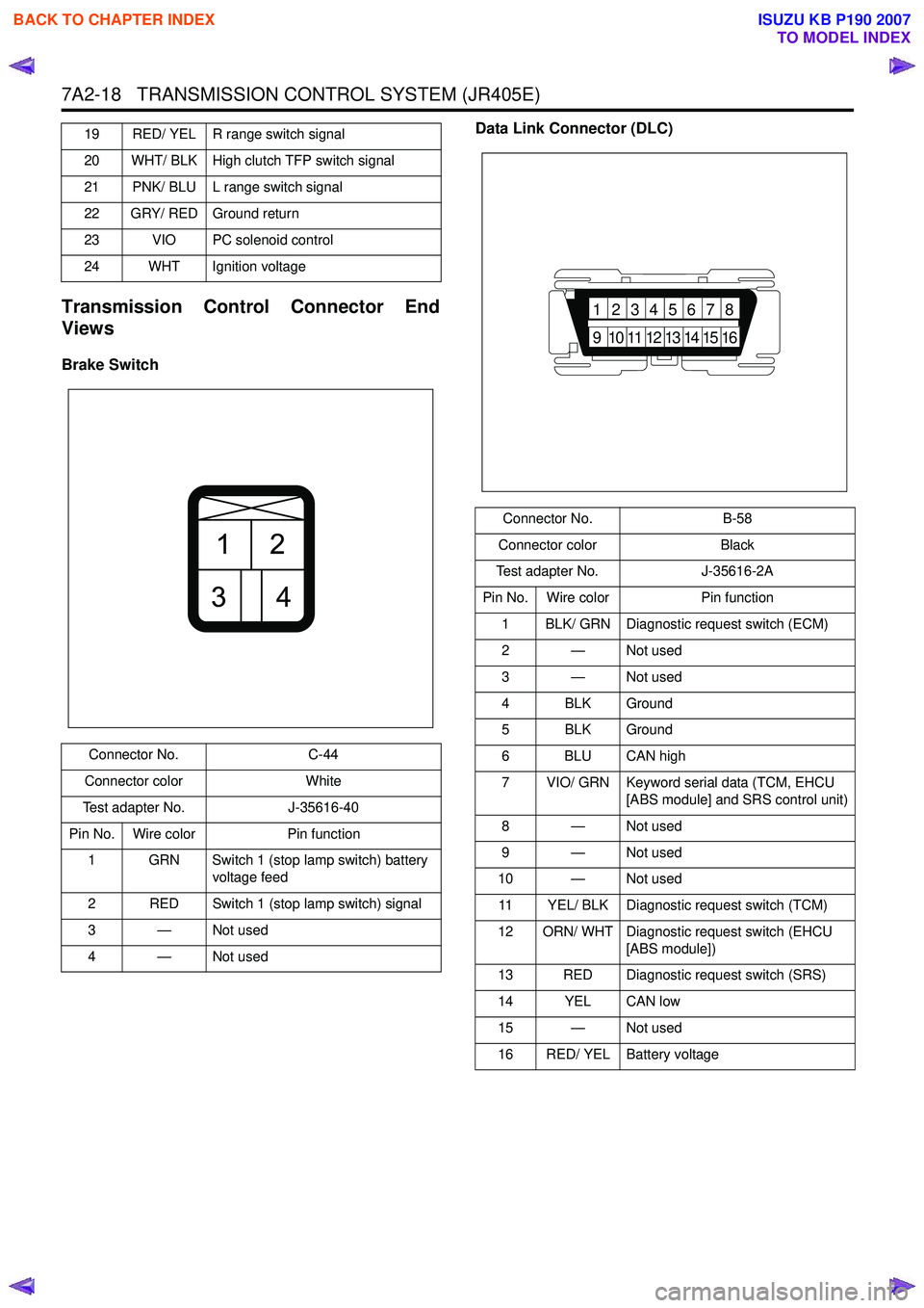
Transmission Control Connector End
Views
Brake Switch Data Link Connector (DLC)
19 RED/ YEL R range switch signal
20 WHT/ BLK High clutch TFP switch signal
21 PNK/ BLU L range switch signal
22 GRY/ RED Ground return
23 VIO PC solenoid control
24 WHT Ignition voltage
Connector No. C-44
Connector color White
Test adapter No. J-35616-40
Pin No. Wire color Pin function
1 GRN Switch 1 (stop lamp switch) battery voltage feed
2 RED Switch 1 (stop lamp switch) signal
3—Not used
4—Not used
21
34
Connector No. B-58
Connector color Black
Test adapter No. J-35616-2A
Pin No. Wire color Pin function
1 BLK/ GRN Diagnostic request switch (ECM)
2 — Not used
3 — Not used
4 BLK Ground
5 BLK Ground
6 BLU CAN high
7 VIO/ GRN Keyword serial data (TCM, EHCU [ABS module] and SRS control unit)
8 — Not used
9 — Not used
10 — Not used
11 YEL/ BLK Diagnostic request switch (TCM)
12 ORN/ WHT Diagnostic request switch (EHCU [ABS module])
13 RED Diagnostic request switch (SRS)
14 YEL CAN low
15 — Not used
16 RED/ YEL Battery voltage
87654321
16151413121110
9
BACK TO CHAPTER INDEX
TO MODEL INDEX
ISUZU KB P190 2007
Page 4306 of 6020
7A2-22 TRANSMISSION CONTROL SYSTEM (JR405E)
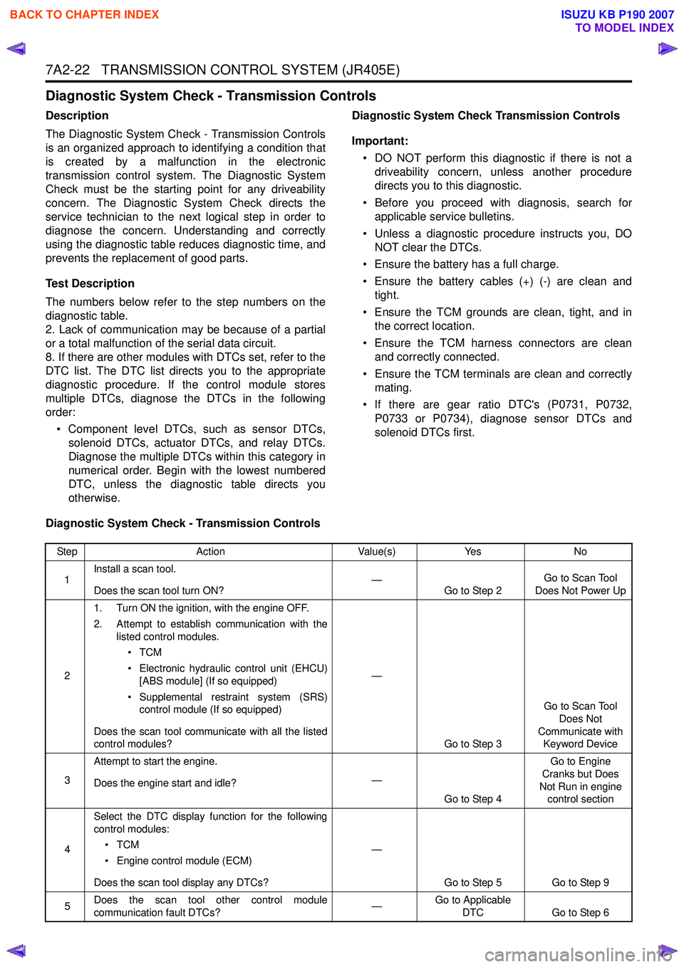
Diagnostic System Check - Transmission Controls
Description
The Diagnostic System Check - Transmission Controls
is an organized approach to identifying a condition that
is created by a malfunction in the electronic
transmission control system. The Diagnostic System
Check must be the starting point for any driveability
concern. The Diagnostic System Check directs the
service technician to the next logical step in order to
diagnose the concern. Understanding and correctly
using the diagnostic table reduces diagnostic time, and
prevents the replacement of good parts.
Test Description
The numbers below refer to the step numbers on the
diagnostic table.
2. Lack of communication may be because of a partial
or a total malfunction of the serial data circuit.
8. If there are other modules with DTCs set, refer to the
DTC list. The DTC list directs you to the appropriate
diagnostic procedure. If the control module stores
multiple DTCs, diagnose the DTCs in the following
order:
• Component level DTCs, such as sensor DTCs, solenoid DTCs, actuator DTCs, and relay DTCs.
Diagnose the multiple DTCs within this category in
numerical order. Begin with the lowest numbered
DTC, unless the diagnostic table directs you
otherwise. Diagnostic System Check Transmission Controls
Important: • DO NOT perform this diagnostic if there is not a driveability concern, unless another procedure
directs you to this diagnostic.
• Before you proceed with diagnosis, search for applicable service bulletins.
• Unless a diagnostic procedure instructs you, DO NOT clear the DTCs.
• Ensure the battery has a full charge.
• Ensure the battery cables (+) (-) are clean and tight.
• Ensure the TCM grounds are clean, tight, and in the correct location.
• Ensure the TCM harness connectors are clean and correctly connected.
• Ensure the TCM terminals are clean and correctly mating.
• If there are gear ratio DTC's (P0731, P0732, P0733 or P0734), diagnose sensor DTCs and
solenoid DTCs first.
Diagnostic System Check - Transmission Controls
Step Action Value(s)Yes No
1 Install a scan tool.
Does the scan tool turn ON? —
Go to Step 2 Go to Scan Tool
Does Not Power Up
2 1. Turn ON the ignition, with the engine OFF.
2. Attempt to establish communication with the listed control modules.
•TCM
• Electronic hydraulic control unit (EHCU) [ABS module] (If so equipped)
• Supplemental restraint system (SRS) control module (If so equipped)
Does the scan tool communicate with all the listed
control modules? —
Go to Step 3 Go to Scan Tool
Does Not
Communicate with Keyword Device
3 Attempt to start the engine.
Does the engine start and idle? —
Go to Step 4 Go to Engine
Cranks but Does
Not Run in engine control section
4 Select the DTC display function for the following
control modules:
•TCM
• Engine control module (ECM)
Does the scan tool display any DTCs? —
Go to Step 5 Go to Step 9
5 Does the scan tool other control module
communication fault DTCs? —Go to Applicable
DTC Go to Step 6
BACK TO CHAPTER INDEX
TO MODEL INDEX
ISUZU KB P190 2007
Page 4313 of 6020
![ISUZU KB P190 2007 Workshop Repair Manual TRANSMISSION CONTROL SYSTEM (JR405E) 7A2-29
Scan Tool Does Not Communicate with Keyword Device
Circuit Description
The TCM, electronic hydraulic control unit (EHCU)
[ABS module] and supplemental r ISUZU KB P190 2007 Workshop Repair Manual TRANSMISSION CONTROL SYSTEM (JR405E) 7A2-29
Scan Tool Does Not Communicate with Keyword Device
Circuit Description
The TCM, electronic hydraulic control unit (EHCU)
[ABS module] and supplemental r](/manual-img/61/57177/w960_57177-4312.png)
TRANSMISSION CONTROL SYSTEM (JR405E) 7A2-29
Scan Tool Does Not Communicate with Keyword Device
Circuit Description
The TCM, electronic hydraulic control unit (EHCU)
[ABS module] and supplemental restraint system
(SRS) control module all communicate with the scan
tool over the Keyword serial data link.
Diagnostic Aids
The following conditions will cause a loss of Keyword
serial data communication between the scan tool and
the TCM.
• A Keyword serial data circuit open • A Keyword serial data circuit shorted to ground
• A Keyword serial data circuit shorted to voltage
• An internal condition within a module or connector on the Keyword serial data circuit, that causes a
short to voltage or ground to the Keyword serial
data circuit
Schematic Reference: Transmission Controls
Schematics
Connector End View Reference: Transmission
Controls Connector End Views or TCM Connector End
Views
Circuit/ System Testing Scan Tool Does Not Communicate with Keyward Device
Step Action Value(s)Yes No
1 Did you perform the Diagnostic System Check -
Engine Controls? —
Go to Step 2 Go to Diagnostic
System Check - Transmission Controls
2 1. Install a scan tool.
2. Turn ON the ignition, with the engine OFF.
3. Attempt to establish communication with the listed control modules.
•TCM
• Electronic hydraulic control unit (EHCU) [ABS module] (If so equipped)
• Supplemental restraint system (SRS) control module (If so equipped)
Does the scan tool communicate with any of the
listed control modules? —
Go to Step 3 Go to Step 7
3 Does the scan tool communicate with the TCM?
—Go to Step 4 Go to Lost
Communication with
The Transmission Control Module (TCM)
4 Notice:
If no ABS is installed, skip to Step 5.
Does the scan tool communicate with the EHCU? —
Go to Step 5 Go to Diagnostic
System Check - Anti-lock Brake Controls
5 Notice:
If no SRS is installed, skip to Step 6.
Does the scan tool communicate with the SRS
control module? —
Go to Step 6 Go to Diagnostic
System Check -SRS Controls
6 Test the Keyword serial data circuit for an
intermittently short to ground or intermittently short
to voltage. Then, test the Keyword serial data
circuit for an intermittently open (based on which
control module did not communicate) at the
connection in the circuit.
Did you find and correct the condition? —
Go to Step 15 System OK
7 1. Inspect for an intermittent, for a poor
connection and for corrosion at the data link
connector (DLC) (pin 7 of B-58).
2. Repair the connection(s) as necessary.
Did you find and correct the condition? —
Go to Step 15 Go to Step 8
BACK TO CHAPTER INDEX
TO MODEL INDEX
ISUZU KB P190 2007