Page 5303 of 6020
ELECTRICAL-BODY AND CHASSIS 8A-365
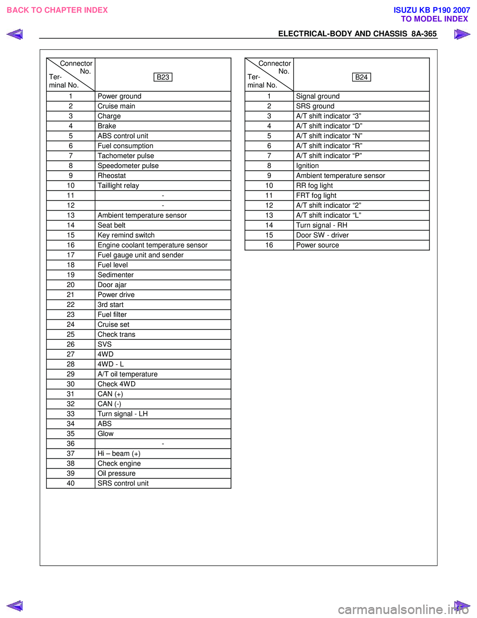
Connector
Ter- No.
minal No.
B23
1 Power ground
2 Cruise main
3 Charge
4 Brake
5 ABS control unit
6 Fuel consumption
7 Tachometer pulse
8 Speedometer pulse
9 Rheostat
10 Taillight relay
11 -
12 -
13 Ambient temperature sensor
14 Seat belt
15 Key remind switch
16 Engine coolant temperature sensor
17 Fuel gauge unit and sender
18 Fuel level
19 Sedimenter
20 Door ajar
21 Power drive
22 3rd start
23 Fuel filter
24 Cruise set
25 Check trans
26 SVS
27 4W D
28 4W D - L
29 A/T oil temperature
30 Check 4W D
31 CAN (+)
32 CAN (-)
33 Turn signal - LH
34 ABS
35 Glow
36 -
37 Hi – beam (+)
38 Check engine
39 Oil pressure
40 SRS control unit
Connector
Ter- No.
minal No.
B24
1 Signal ground
2 SRS ground
3 A/T shift indicator “3”
4 A/T shift indicator “D”
5 A/T shift indicator “N”
6 A/T shift indicator “R”
7 A/T shift indicator “P”
8 Ignition
9 Ambient temperature sensor
10 RR fog light
11 FRT fog light
12 A/T shift indicator “2”
13 A/T shift indicator “L”
14 Turn signal - RH
15 Door SW - driver
16 Power source
BACK TO CHAPTER INDEX TO MODEL INDEXISUZU KB P190 2007
Page 5304 of 6020
8A-366 ELECTRICAL-BODY AND CHASSIS
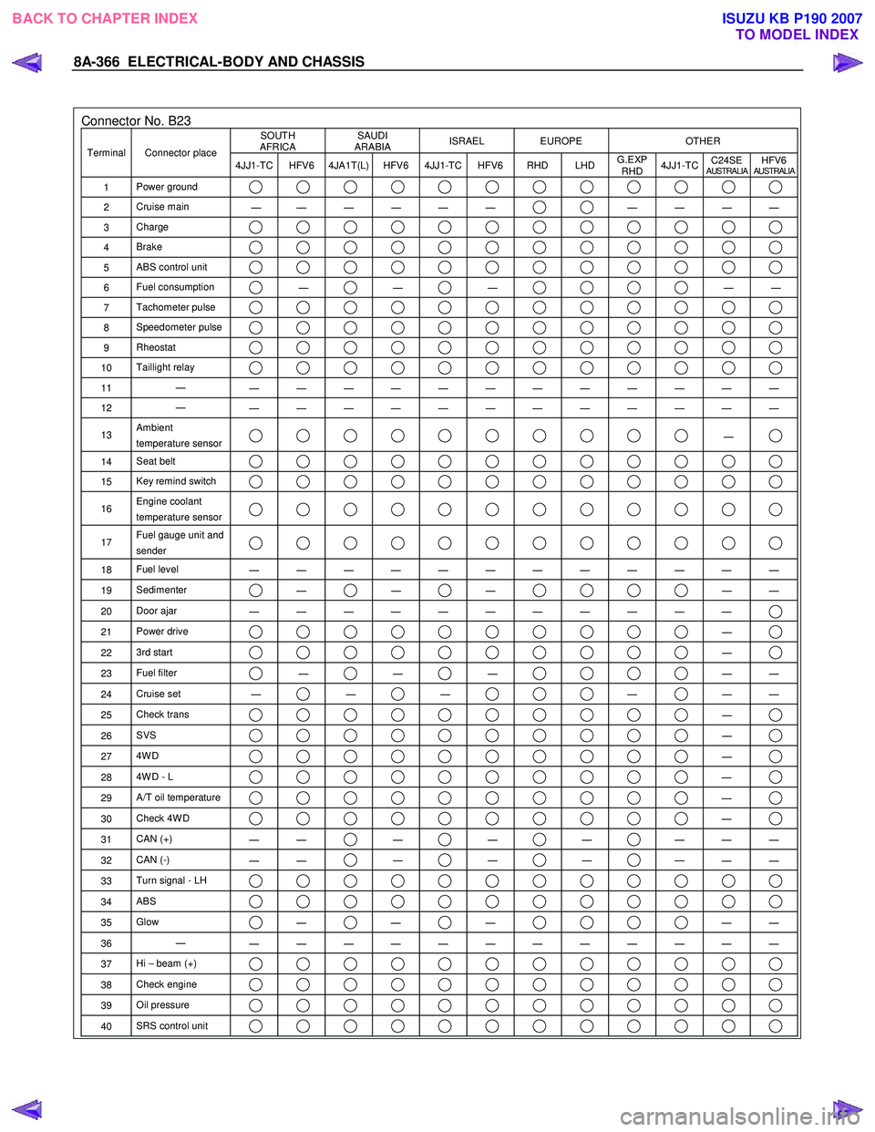
Connector No. B23 SOUTH
AFRICA SAUDI
ARABIA ISRAEL EUROPE OTHER
Terminal Connector place
4JJ1-TC HFV6 4JA1T(L) HFV6 4JJ1-TC HFV6 RHD LHD G.EXP
RHD 4JJ1-TC
C24SE
AUSTRALIAHFV6AUSTRALIA
1
Power ground
2 Cruise main
―
― ― ― ― ― ― ― ― ―
3
Charge
4 Brake
5 ABS control unit
6 Fuel consumption ―
―
―
―
―
7 Tachometer pulse
8 Speedometer pulse
9 Rheostat
10 Taillight relay
11 ―
― ― ― ― ― ― ― ― ― ― ― ―
12 ―
― ― ― ― ― ― ― ― ― ― ― ―
13 Ambient
temperature sensor ―
14 Seat belt
15 Key remind switch
16 Engine coolant
temperature sensor
17 Fuel gauge unit and
sender
18 Fuel level
― ― ― ― ― ― ― ― ― ― ― ―
19 Sedimenter ―
―
―
―
―
20 Door ajar
― ― ― ― ― ― ― ― ― ― ―
21 Power drive ―
22 3rd start ―
23 Fuel filter ―
―
―
―
―
24 Cruise set
― ―
―
―
―
―
25 Check trans ―
26 SVS ―
27 4W D ―
28 4W D - L ―
29 A/T oil temperature ―
30 Check 4W D ―
31 CAN (+)
― ― ―
―
―
― ― ―
32
CAN (-)
― ― ―
―
―
― ― ―
33
Turn signal - LH
34 ABS
35 Glow ―
―
―
―
―
36 ―
― ― ― ― ― ― ― ― ― ― ― ―
37 Hi – beam (+)
38 Check engine
39 Oil pressure
40 SRS control unit
BACK TO CHAPTER INDEX
TO MODEL INDEXISUZU KB P190 2007
Page 5307 of 6020
ELECTRICAL-BODY AND CHASSIS 8A-369
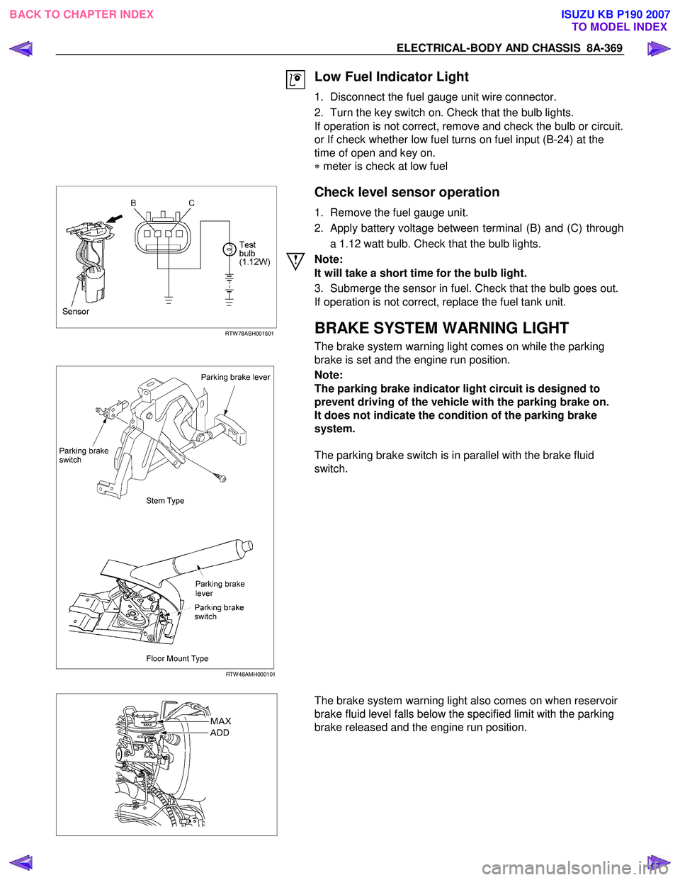
Low Fuel Indicator Light
1. Disconnect the fuel gauge unit wire connector.
2. Turn the key switch on. Check that the bulb lights.
If operation is not correct, remove and check the bulb or circuit.
or If check whether low fuel turns on fuel input (B-24) at the
time of open and key on.
∗ meter is check at low fuel
RTW 78ASH001501
Check level sensor operation
1. Remove the fuel gauge unit.
2. Apply battery voltage between terminal (B) and (C) through a 1.12 watt bulb. Check that the bulb lights.
Note:
It will take a short time for the bulb light.
3. Submerge the sensor in fuel. Check that the bulb goes out.
If operation is not correct, replace the fuel tank unit.
BRAKE SYSTEM WARNING LIGHT
The brake system warning light comes on while the parking
brake is set and the engine run position.
RTW 48AMH000101
Note:
The parking brake indicator light circuit is designed to
prevent driving of the vehicle with the parking brake on.
It does not indicate the condition of the parking brake
system.
The parking brake switch is in parallel with the brake fluid
switch.
The brake system warning light also comes on when reservoir
brake fluid level falls below the specified limit with the parking
brake released and the engine run position.
BACK TO CHAPTER INDEX TO MODEL INDEXISUZU KB P190 2007
Page 5345 of 6020
ELECTRICAL-BODY AND CHASSIS 8A-407
TROUBLESHOOTING
QUICK CHART FOR CHECK POINTS
Check Points Fuse C21
(20A) Power
Window &
Door Lock Switch Door
Lock
Switch Key Cylinder
switch Door Lock Actuator
Cable
Trouble Mode Driver’s
side Driver’s
side D/S P/S Passen
ger’s side RR-RH RR-LH
Harness
1. All the doors do not
lock and unlock
2. All the doors do not get locked (or
unlocked)
3. Driver’s side door
does not get locked
(or unlocked)
4. FRT passenger’s side
door does not get
locked (or unlocked)
5. RR door-RH does not
get locked (or
unlocked)
6. RR door-LH does not
get locked (or
unlocked)
7. Door lock does not
operate when
operating from the
driver’s seat side
BACK TO CHAPTER INDEX
TO MODEL INDEXISUZU KB P190 2007
Page 5467 of 6020
ELECTRICAL-BODY AND CHASSIS 8A-529
KEYLESS ENTRY
PARTS LOCATION (RHD)
RTW 78AXF041101 & RTW 78AXF047301
BACK TO CHAPTER INDEX TO MODEL INDEXISUZU KB P190 2007
Page 5476 of 6020
8A-538 ELECTRICAL-BODY AND CHASSIS
TROUBLESHOOTING
Diagnostic procedure
•
Check the operation "Lock / unlock" by using
transmitter (remote key) on the vehicle.
• Check the operation "ON / OFF" for Driver side
door SW on the vehicle.
• Perform the Keyless entry System Check.
Diagnostic Aids
An intermittent may be caused by the following:
• Poor connections.
• Miss routed harness.
• Rubbed through wire insulation.
• Broken wire inside the insulation.
Check for the following conditions:
• Poor connection at keyless entry control unit-
Inspect harness connectors for backed out
terminals, improper mating, broken locks,
improperly formed or damaged terminals, and poo
r
terminal to wire connection.
• Damaged harness-Inspect the wiring harness fo
r
damage.
Check the Electro-Magnetic Interference (EMI)
• Location of vehicle check
Move the vehicle to a new location and perform
the check again.
• Non-OEM Parts.
Switch is “OFF” or remove the Non-OEM parts and
perform the check again.
• Other
Remove the accessory and another key from key.
Check the other items.
• Battery voltage is low.
• Keyless entry programming functions.
• Registration for security code.
• Ignition switch operation.
• Meter system is malfunction.
Check the operation
Check the operation "Lock / unlock" by using
transmitter (remote key) on the vehicle.
Notice
If so equipped the Anti Theft, Refer to ANTI
THEFT SYSTEM in 11B Section.
BACK TO CHAPTER INDEX TO MODEL INDEXISUZU KB P190 2007
Page 5477 of 6020
ELECTRICAL-BODY AND CHASSIS 8A-539
Keyless Entry System Check
Step Action Value (s) Yes No
1 Check the fuse for the keyless entry power feed
circuit. (EB16 10A)
If a problem found, repair as necessary.
W as the problem found? — Verify repair Go to Step 2
2
1. Check the KCU (Keyless Entry Control Unit)
ground circuit for an open, or short to voltage.
Also, check the KCU ignition feed circuit for an
open or short to ground and the KCU ground
circuit for an open.
2. If a problem is found, repair as necessary.
W as the problem found? — Verify repair Go to Step 3
3
1. Check the front drive side SW circuit for an open,
or short to voltage.
2. If a problem is found, repair as necessary.
W as the problem found? — Verify repair Go to Step 4
4
1. Check the operation "Lock / unlock" by using
transmitter (Remote key) on the vehicle.
W as the problem found? — Go to
Diagnostic Chart Go to
Diagnostic Aids
BACK TO CHAPTER INDEX TO MODEL INDEXISUZU KB P190 2007
Page 5478 of 6020
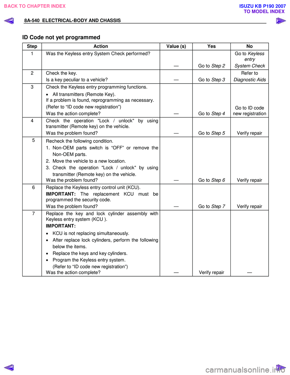
8A-540 ELECTRICAL-BODY AND CHASSIS
ID Code not yet programmed
Step Action Value (s) Yes No
1 W as the Keyless entry System Check performed?
— Go to Step 2 Go to
Keyless
entry
System Check
2 Check the key. Is a key peculiar to a vehicle? — Go to Step 3 Refer to
Diagnostic Aids
3 Check the Keyless entry programming functions.
• All transmitters (Remote Key).
If a problem is found, reprogramming as necessary.
(Refer to “ID code new registration”)
W as the action complete? — Go to Step 4 Go to ID code
new registration
4 Check the operation "Lock / unlock" by using transmitter (Remote key) on the vehicle.
W as the problem found? — Go to Step 5 Verify repair
5
Recheck the following condition.
1. Non-OEM parts switch is “OFF” or remove the Non-OEM parts.
2. Move the vehicle to a new location.
3. Check the operation "Lock / unlock" by using transmitter (Remote key) on the vehicle.
W as the problem found? — Go to Step 6 Verify repair
6 Replace the Keyless entry control unit (KCU).
IMPORTANT: The replacement KCU must be
programmed the security code.
W as the problem found? — Go to Step 7 Verify repair
7 Replace the key and lock cylinder assembly with
Keyless entry system (KCU ).
IMPORTANT:
• KCU is not replacing simultaneously.
• After replace lock cylinders, perform the following
below the items.
• Replace the keys and key cylinders.
• Program the Keyless entry system.
(Refer to “ID code new registration”)
W as the action complete? — Verify repair —
BACK TO CHAPTER INDEX
TO MODEL INDEXISUZU KB P190 2007