Page 4863 of 6020
TRANSFER CASE 7D-33
226R300003
11. Use a press to install the 2-4 hub.
12. Install the hub snap ring.
13. Install the synchronizer key springs, the synchronize
r
key, and the 2-4 sleeve to the 2-4 hub. The key and
the open end of the springs must be facing in the
opposite direction.
Legend
(1) Retaining Ring
(2) Carrier and Gear ASM
(3) Thrust Needle Bearing
(4) Sungear Input Shaft
(5) Planetary Dog Teeth
(6) Dog Teeth Snap Ring
BACK TO CHAPTER INDEX
TO MODEL INDEX
ISUZU KB P190 2007
Page 4864 of 6020
7D-34 TRANSFER CASE
14. Insert the H-L sleeve into the main shaft.
226R300023
Legend
(1) H-L Sleeve
(3) Synchronizer Key and Key Spring
(2) 2-4 Sleeve
15. Install the sleeve to the H-L shift assembly.
16. Install the sleeve to the 2-4 shift assembly.
17. Coat the area around each of the shift assembl
y
insertion holes (transfer case) with transfer oil.
18. Install the main shaft together with the H-L shift
assembly and the 2-4 shift assembly to the shift drum.
BACK TO CHAPTER INDEX
TO MODEL INDEX
ISUZU KB P190 2007
Page 4915 of 6020
TRANSFER CONTROL SYSTEM 7D1-41
CONNECTOR LIST
No. Connector face No. Connector face
B13
White
Fan switch B85
W eld splice 7 (Ground)
B23
White
Meter-A B95
White
Keyless entry control unit
B24
White
Meter-B B96
Gray PIM1
B54
White
J/B I2 B97
WhitePIM2
B56
White
J/B I4 C2
SilverEngine room-RH ground
B62
White
Ignition switch (IGSUB: G1) C4
Sky blueFront wiper motor
B63
White
Ignition switch (IGSUB: G2) C5
~
C14 NOT USED
B64
W eld splice 1 (Illumination) C36
SilverEngine room-LH; ground
B65
W eld splice 2 (Ground) C56
(C24SE)
ECM
B66
White
4 ×4 switch C56
(4JH1-TC)
Black
ECM-A
BACK TO CHAPTER INDEX
TO MODEL INDEX
ISUZU KB P190 2007
Page 4941 of 6020

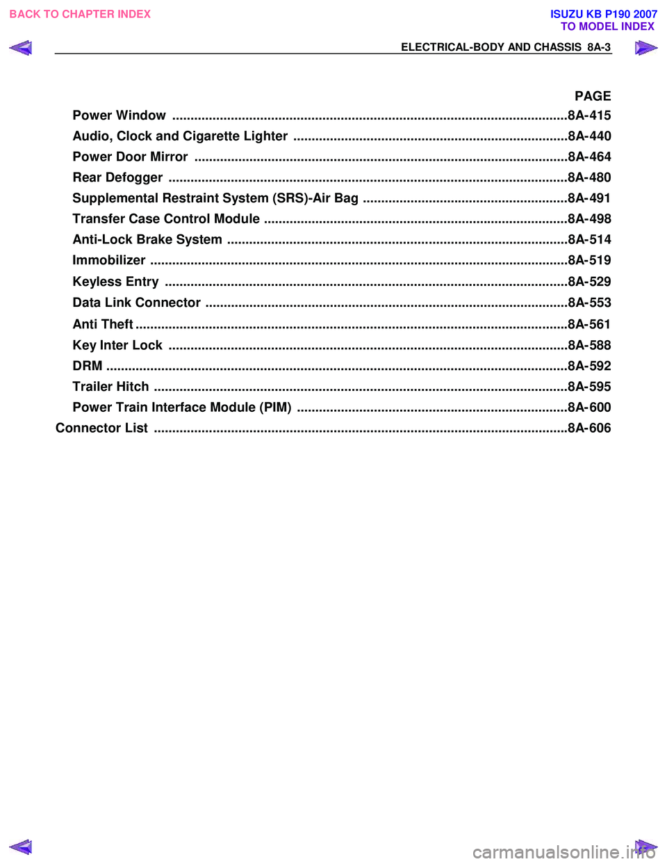
ELECTRICAL-BODY AND CHASSIS 8A-3
PAGE
Power Window ............................................................................................................8A- 41 5
Audio, Clock and Cigarette Lighter ...........................................................................8A- 440
Power Door Mirror ......................................................................................................8A- 464
Rear Defogger .............................................................................................................8A- 480
Supplemental Restraint System (SRS)-Air Bag ........................................................8A- 491
Transfer Case Control Module ...................................................................................8A- 498
Anti-Lock Brake System .............................................................................................8A- 514
Immobilizer ..................................................................................................................8 A- 519
Keyless Entry ..............................................................................................................8A- 529
Data Link Connector ...................................................................................................8A- 553
Anti Theft ..................................................................................................................... .8A- 561
Key Inter Lock .............................................................................................................8A- 588
DRM ........................................................................................................................... ...8A- 592
Trailer Hitch ................................................................................................................. 8A- 595
Power Train Interface Module (PIM) ..........................................................................8A- 600
Connector List ................................................................................................................ .8A- 606
BACK TO CHAPTER INDEX
TO MODEL INDEX
ISUZU KB P190 2007
Page 5048 of 6020
8A-110 ELECTRICAL-BODY AND CHASSIS
REMOVAL AND INSTALLATION
This illustration is based on RHD model
STARTER SWITCH
Removal
1. Steering Lock Assembly • Refer to Section 3B" STEERING COLUMN" for steering
lock assembly removal steps.
2. Starter Switch
Installation
Follow the removal procedure in the reverse order to install the
starter switch.
INSPECTION AND REPAIR
B62 B63
STARTER SWITCH
Switch Connections
Terminal No.
Starter
switch key
position B62
2
(B2) B62
4
(ACC) B62
1
(IG2) B63
1
(ST) B63
3
(B1) B62
3
(IG1)
Removed
OFF
ACC Inserted
ON
START
LOCK
RTW 78ASH003001
Starter relay
Check continuity between the relay terminals.
1 - 4............................ No continuity
(W hen battery voltage is applied between 2 and 3)
1 - 4............................ Continuity
BACK TO CHAPTER INDEX TO MODEL INDEXISUZU KB P190 2007
Page 5187 of 6020
ELECTRICAL-BODY AND CHASSIS 8A-249
CIRCUIT DIAGRAM C24SE (RHD) WITH KEYLESS ENTRY
RTW 780XF012801
BACK TO CHAPTER INDEX TO MODEL INDEXISUZU KB P190 2007
Page 5190 of 6020
8A-252 ELECTRICAL-BODY AND CHASSIS
CIRCUIT DIAGRAM C24SE (LHD) WITH KEYLESS ENTRY
RTW 780XF013001
BACK TO CHAPTER INDEX TO MODEL INDEXISUZU KB P190 2007
Page 5201 of 6020
ELECTRICAL-BODY AND CHASSIS 8A-263
INSPECTION AND REPAIR
R9 R10
R1 R6
DOOR SWITCH
Door Switch Connections
Connector
SW No.
R9
R10
R1 R6
position Terminal No.
1 Body Ground
PUSHED
RELEASED
W arning function Operational conditions
Key left in starter switch The buzzer sounds when both the key remind switch and the front door
switch-driver side are turned on.
To stop the sound of the buzzer, turn OFF the starter switch and remove the
key from the starter switch.
Lighting switch left on The buzzer sounds when the starter switch is turned from the “ON” to “OFF”
position while the lighting switch is ON position.
To stop the sound of the buzzer, turn OFF the lighting switch.
B62 B63
KEY REMIND SWITCH (STARTER
SWITCH)
Switch Connections
Connector
No. B63
Starter Terminal
switch key position No.
2 4
Removed
OFF
ACC Inserted
ON
START
LOCK
BACK TO CHAPTER INDEX TO MODEL INDEXISUZU KB P190 2007