2007 ISUZU KB P190 key
[x] Cancel search: keyPage 5651 of 6020
9A-16 SUPPLEMENTAL RESTRAINT SYSTEM
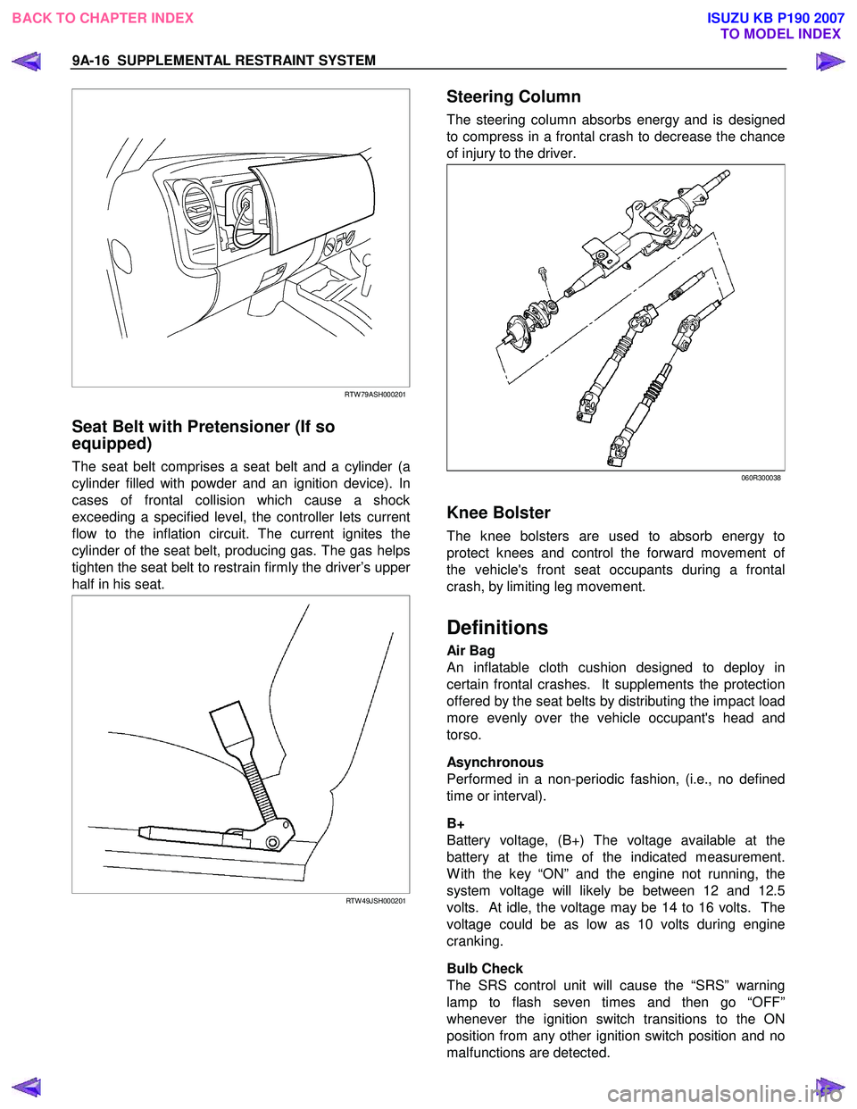
RTW 79ASH000201
Seat Belt with Pretensioner (If so
equipped)
The seat belt comprises a seat belt and a cylinder (a
cylinder filled with powder and an ignition device). In
cases of frontal collision which cause a shock
exceeding a specified level, the controller lets current
flow to the inflation circuit. The current ignites the
cylinder of the seat belt, producing gas. The gas helps
tighten the seat belt to restrain firmly the driver’s uppe
r
half in his seat.
RTW 49JSH000201
Steering Column
The steering column absorbs energy and is designed
to compress in a frontal crash to decrease the chance
of injury to the driver.
060R300038
Knee Bolster
The knee bolsters are used to absorb energy to
protect knees and control the forward movement o
f
the vehicle's front seat occupants during a frontal
crash, by limiting leg movement.
Definitions
Air Bag
An inflatable cloth cushion designed to deploy in
certain frontal crashes. It supplements the protection
offered by the seat belts by distributing the impact load
more evenly over the vehicle occupant's head and
torso.
Asynchronous
Performed in a non-periodic fashion, (i.e., no defined
time or interval).
B+
Battery voltage, (B+) The voltage available at the
battery at the time of the indicated measurement.
W ith the key “ON” and the engine not running, the
system voltage will likely be between 12 and 12.5
volts. At idle, the voltage may be 14 to 16 volts. The
voltage could be as low as 10 volts during engine
cranking.
Bulb Check
The SRS control unit will cause the “SRS” warning
lamp to flash seven times and then go “OFF”
whenever the ignition switch transitions to the ON
position from any other ignition switch position and no
malfunctions are detected.
BACK TO CHAPTER INDEX TO MODEL INDEXISUZU KB P190 2007
Page 5656 of 6020
SUPPLEMENTAL RESTRAINT SYSTEM 9A-21
On–Vehicle Service
Service Precaution
WARNING: WHEN PERFORMING SERVICE ON OR
AROUND SRS COMPONENTS OR SRS WIRING,
FOLLOW THE PROCEDURES LISTED BELOW TO
TEMPORARILY DISABLE THE SRS. FAILURE TO
FOLLOW PROCEDURES COULD RESULT IN
POSSIBLE AIR BAG DEPLOYMENT, PERSONAL
INJURY OR OTHERWISE UNNECESSARY SRS
REPAIRS.
The SRS control unit in Driver–Passenger SRS can
maintain sufficient voltage to cause a deployment fo
r
up to 15 seconds after the ignition switch is turned
“OFF,” the battery is disconnected, or the fuse
powering the SRS control unit is removed.
Many of the service procedures require removal of the
“SRS” fuse, and disconnection of the air bag assembl
y
from the deployment loop to avoid an accidental
deployment. If the air bag assembly is disconnected
from the deployment loop as noted in the “Disabling
the SRS” procedure that follows, service can begin
immediately without waiting for the 15 second time
period to expire.
Disabling The SRS
Removal
Turn the ignition switch to “LOCK” and remove the
key.
1. Remove the SRS fuse “SRS”, from the side of the driver’s side of the instrument panel fuse block o
r
disconnect the battery.
2. Disconnect the yellow connector at the base of the steering column.
3. Remove the glove box assembly, refer to “Passenger Air Bag Assembly Replacement” in
this manual.
4. Disconnect the yellow connector behind the glove box assembly.
CAUTION: With the “SRS” fuse removed and
ignition switched “ON”, the “SRS” warning lamp
will be “ON”. This is normal operation and does
not indicate an SRS malfunction.
Enabling The SRS
Installation
CAUTION: Never use the air bag assembly from
another vehicle or different model year air bag
assembly.
Use only a new air bag assembly matched to the
TFR/S which is being repaired.
Turn the ignition switch to “LOCK” and remove the
key.
1. Connect the yellow connector passenger air bag assembly.
2. Install the glove box assembly. Refer to “Passenger air bag assembly replacement” in this
manual.
3. Connect the yellow connector at the base of the steering column.
4. Install the “AIR BAG” fuse “SRS” to the side of the driver’s side of the instrument panel fuse block o
r
connect the battery.
Turn the ignition switch to “ON” and verify that the
“SRS” warning lamp flashes seven times and then
turns to “LOCK”. If it does not operate as described,
perform the “SRS Diagnostic System Check” in this
manual.
Handling / Installation / Diagnosis
1. The air bag assembly should not be subjected to temperatures above 65
°C (150°F).
2. The air bag assembly, and SRS control unit, should not be used if they have been dropped from
a height of 100 centimeters (3.28 feet) or more.
3. W hen the SRS control unit is replaced, it must be oriented with the arrow on the sensor pointing
toward the front of the vehicle. It is very important
for the SRS control unit to be located flat on the
mounting surface, parallel to the vehicle datum
line. It is important that the SRS control unit
mounting surface is free of any dirt or other foreign
material.
4. Do not apply power to the SRS unless all components are connected or a diagnostic chart
requests it, as this will set a diagnostic trouble
code.
5. The “SRS Diagnostic System Check” must be the starting point of any SRS diagnostics. The “SRS
Diagnostic System Check” will verify proper “SRS”
warning lamp operation and will lead you to the
correct chart to diagnose any SRS malfunctions.
Bypassing these procedures may result in
extended diagnostic time, incorrect diagnosis, and
incorrect parts replacement.
BACK TO CHAPTER INDEX TO MODEL INDEXISUZU KB P190 2007
Page 5661 of 6020
9A-26 SUPPLEMENTAL RESTRAINT SYSTEM
26. Temporarily store the driver air bag assembly with
its trim cover facing up, away from the surface
upon which it rests.
Deployment Outside Vehicle (Passenger
Air Bag Assembly)
WARNING: FAILURE TO FOLLOW PROPER SRS
AIR BAG ASSEMBLY DISPOSAL PROCEDURES
CAN RESULT IN AIR BAG DEPLOYMENT WHICH
MAY CAUSE PERSONAL INJURY. UNDEPLOYED
AIR BAG ASSEMBLIES MUST NOT BE DISPOSED
OF THROUGH NORMAL REFUSE CHANNELS.
THE UNDEPLOYED AIR BAG ASSEMBLY
CONTAINS SUBSTANCES THAT CAN CAUSE
SEVERE ILLNESS OR PERSONAL INJURY IF THE
SEALED CONTAINER IS DAMAGED DURING
DISPOSAL. DISPOSAL IN ANY MANNER
INCONSISTENT WITH PROPER PROCEDURES
MAY BE A VIOLATION OF FEDERAL, STATE
AND/OR LOCAL LAWS.
Deployment out of the vehicle is proper when the
vehicle is to be returned to service. This includes, fo
r
example, situations in which a functionally or
cosmetically deficient air bag assembly is replaced.
Deployment and disposal of an air bag assembly is, o
f
course, subject to any required retention period.
For deployment of a live air bag assembly out of the
vehicle, the deployment procedure must be followed
exactly. Always wear safety glasses during this
deployment procedure until the deployed air bag
assembly is scrapped. Before performing the
procedures, you should be familiar with servicing the
SRS system and with proper handling of the air bag
assembly. Procedures should be read fully before
they are performed.
The following procedure requires use of a 5-8840-
2468-0 SRS Deployment Harness with the appropriate
pigtail adapter. The procedure also requires the use
of a 5-8840-2420-0 Passenger Side SRS Module
Deployment Fixture. Do not attempt this procedure
without a 5-8840-2468-0 and adapter, and a 5-8840-
2420-0.
WARNING: FAILURE TO FOLLOW PROCEDURES
IN THE ORDER LISTED MA
Y RESULT IN
PERSONAL INJURY. NEVER CONNECT THE
DEPLOYMENT HARNESS TO ANY POWER
SOURCE BEFORE CONNECTING THE
DEPLOYMENT HARNESS TO THE AIR BAG
ASSEMBLY. THE DEPLOYMENT HARNESS SHALL
REMAIN SHORTED AND NOT BE CONNECTED TO
A POWER SOURCE UNTIL THE AIR BAG IS TO BE
DEPLOYED. THE AIR BAG ASSEMBLY WILL
IMMEDIATELY DEPLOY THE AIR BAG WHEN
A
POWER SOURCE IS CONNECTED TO IT. WEAR
SAFETY GLASSES THROUGHOUT THIS ENTIRE
DEPLOYMENT AND DISPOSAL PROCEDURE.
NOTE: This information applies only to passenger ai
r
bag assembly. Information for disposing of a live
driver air bag assembly can be found in “Deployment
Outside Vehicle” (Driver Air Bag Assembly) in this
section.
1. Turn the ignition switch to “LOCK”, remove the key, and put on the safety glasses.
2. Inspect the 5-8840-2468-0 SRS Deployment Harness and appropriate pigtail adapter fo
r
damage. If the harness or pigtail is damaged,
discard and obtain a replacement.
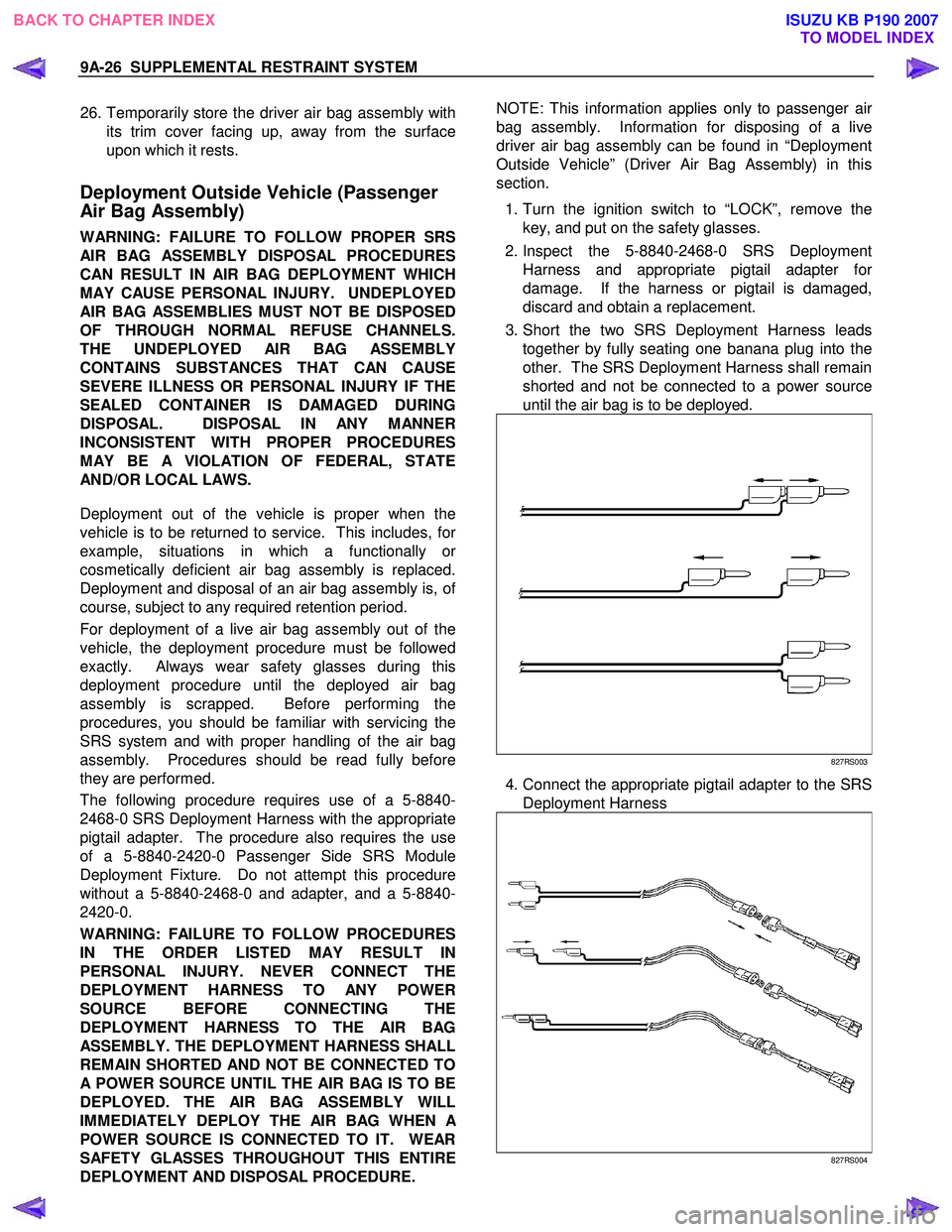
3. Short the two SRS Deployment Harness leads together by fully seating one banana plug into the
other. The SRS Deployment Harness shall remain
shorted and not be connected to a power source
until the air bag is to be deployed.
827RS003
4. Connect the appropriate pigtail adapter to the SRS Deployment Harness
827RS004
BACK TO CHAPTER INDEX TO MODEL INDEXISUZU KB P190 2007
Page 5667 of 6020
9A-32 SUPPLEMENTAL RESTRAINT SYSTEM
Service Precautions for SRS
Component Service
CAUTION: When fasteners are removed, always
reinstall them at the same location from which
they were removed. If a fastener needs to be
replaced, use the correct part number fastener fo
r
that application. If the correct part number
fastener is not available, a fastener of equal size
and strength (or stronger) may be used. Fasteners
that are not reused, and those requiring a thread
locking compound will be called out. The correct
torque value must be used when installing
fasteners that require it. If the above conditions
are not followed, parts or system damage could
result.
WARNING: WHEN PERFORMING SERVICE ON OR
AROUND SRS COMPONENTS OR SRS WIRING,
FOLLOW THE PROCEDURES LISTED BELOW TO
TEMPORARILY DISABLE THE SRS. FAILURE TO
FOLLOW PROCEDURES COULD RESULT IN
POSSIBLE AIR BAG DEPLOYMENT, PERSONAL
INJURY OR OTHERWISE UNNEEDED SRS
REPAIRS.
The SRS control unit in the Driver–Passenger SRS
can maintain sufficient voltage to cause a deployment
for up to 15 seconds after the ignition switch is turned
“OFF,” the battery is disconnected, or the fuse
powering the SRS control unit is removed.
Many of the service procedures require removal of the
“SRS” fuse, and disconnection of the air bag assembl
y
from the deployment loop to avoid an accidental
deployment. If the air bag assembly is disconnected
from the deployment loop as noted in the “Disabling
the SRS” procedure that follows, service can begin
immediately without waiting for the 15 second time
period to expire.
Disabling The SRS
Removal
Turn the ignition switch to “OFF” and turn the steering
wheel so that the vehicle's wheels are pointing straight
ahead.
1. Remove the SRS fuse “SRS” from the left dash side lower fuse block or disconnect the battery.
2. Disconnect the yellow connector at the base o
f
steering column.
3. Remove the glove box assembly; Refer to “Passenger air bag assembly replacement” in this
section.
4. Disconnect the passenger air bag assembly yello
w
connector behind the glove box assembly.
CAUTION: With the “SRS” fuse removed and the
ignition switch to “ON,” the “SRS” warning lamp
will be “ON.” This is normal operation and does
not indicate an SRS malfunction.
Enabling The SRS
Installation
Turn the ignition switch to “LOCK” and remove the
key.
1. Connect the yellow connector passenger air bag assembly.
2. Install the glove box assembly. Refer to “Passenger Air Bag Assembly Replacement” in
this section.
3. Connect the yellow connector at the base of the steering column.
4. Install the “AIR BAG” fuse “SRS” to the left dash side lower fuse block or connect the battery.
Turn the ignition switch to “ON” and verify that the
“SRS” warning lamp flashes seven times and then
turns to “LOCK”. If it does not operate as described,
perform the “SRS Diagnostic System Check” in this
section.
Handling / Installation / Diagnosis
1. Air bag assembly should not be subjected to
temperatures above 65 °C (150 °F).
2.
Air bag assembly, and SRS control unit should not
be used if they have been dropped from a height
of 100 centimeters (3.28 feet) or more.
3. W hen a SRS control unit is replaced, it must be oriented with the arrow on the SRS control unit
pointing toward the front of the vehicle. It is ver
y
important for the SRS control unit to be located flat
on the mounting surface, parallel to the vehicle
datum line. It is important that the SRS control unit
mounting surface is free of any dirt or other foreign
material.
4. Do not apply power to the SRS unless all components are connected or a diagnostic chart
requests it, as this will set a diagnostic trouble
code.
5. The “SRS Diagnostic System Check” must be the starting point of any SRS diagnostics. The “SRS
Diagnostic System Check” will verify proper “SRS”
warning lamp operation and will lead you to the
correct chart to diagnose any SRS malfunctions.
Bypassing these procedures may result in
extended diagnostic time, incorrect diagnosis, and
incorrect parts replacements.
BACK TO CHAPTER INDEX TO MODEL INDEXISUZU KB P190 2007
Page 5670 of 6020
SUPPLEMENTAL RESTRAINT SYSTEM 9A-35
SRS Control Unit
Service Precautions
WARNING: DURING SERVICE PROCEDURES, BE
VERY CAREFUL WHEN HANDLING THE SRS
CONTROL UNIT. NEVER STRIKE OR JAR THE SRS
CONTROL UNIT. UNDER SOME
CIRCUMSTANCES, IT COULD CAUSE
DEPLOYMENT AND RESULT IN PERSONAL
INJURY OR IMPROPER OPERATION OF THE
SUPPLEMENTAL RESTRAINT SYSTEM (SRS).
THE SRS CONTROL UNIT MOUNTING BRACKET
BOLTS MUST BE CAREFULLY TORQUED TO
ASSURE PROPER OPERATION. NEVER POWER
UP THE SRS WHEN THE SRS CONTROL UNIT IS
NOT RIGIDLY ATTACHED TO THE VEHICLE. THE
SRS CONTROL UNIT COULD BE ACTIVATED
WHEN POWERED WHILE NOT RIGIDLY
ATTACHED TO THE VEHICLE WHICH COULD
CAUSE DEPLOYMENT AND RESULT IN
PERSONAL INJURY.
WARNING: PROPER OPERATION OF THE SRS
CONTROL UNIT REQUIRES THE SRS CONTROL
UNIT TO BE RIGIDLY ATTACHED TO THE
VEHICLE STRUCTURE AND THAT THE ARROW
ON THE SENSOR BE POINTING TOWARD THE
FRONT OF THE VEHICLE.
The SRS control unit is specifically calibrated and is
keyed to the SRS control unit location SRS wiring
harness. Caution should be used to ensure prope
r
location of the SRS control unit. The keying of the
SRS control unit to its location and wiring harness
connectors should never be modified in the field.
Removal
1. Disable the SRS (Refer to “Disabling the SRS” in this section).
2. Remove the transmission knob (for M/T) and transfer lever knob.
3. Remove the front console assembly and disconnect the wiring harness connector.
4. Disconnect the SRS control unit harness connector.
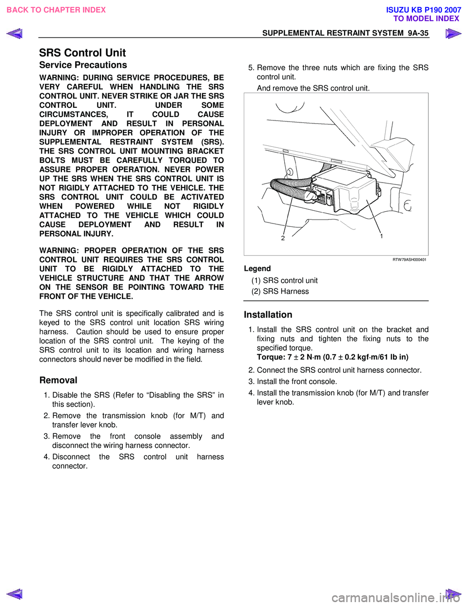
5. Remove the three nuts which are fixing the SRS
control unit.
And remove the SRS control unit.
RTW 79ASH000401
Legend
(1) SRS control unit
(2) SRS Harness
Installation
1. Install the SRS control unit on the bracket and
fixing nuts and tighten the fixing nuts to the
specified torque.
Torque: 7 ±
±±
±
2 N ⋅
⋅⋅
⋅
m (0.7 ±
±±
±
0.2 kgf ⋅
⋅⋅
⋅
m/61 lb in)
2. Connect the SRS control unit harness connector.
3. Install the front console.
4. Install the transmission knob (for M/T) and transfe
r
lever knob.
BACK TO CHAPTER INDEX TO MODEL INDEXISUZU KB P190 2007
Page 5678 of 6020
SUPPLEMENTAL RESTRAINT SYSTEM 9A-43
Pretensioner Seat Belt (If so equipped)
Service Precaution
WARNING: WHEN PERFORMING SERVICE ON OR
AROUND THE PRETENSIONER SEAT BELT OR
THE PRETENSIONER SEAT BELT WIRING,
FOLLOW THE PROCEDURES LISTED BELOW TO
TEMPORARILY DISABLE THE PRETENSIONER
SEAT BELT.
FAILURE TO FOLLOW PROCEDURES COULD
RESULT IN POSSIBLE THE PRETENSIONER SEAT
BELT DEPLOYMENT, PERSONAL INJURY OR
OTHERWISE UNNEEDED THE PRETENSIONER
SEAT BELT REPAIR.
AS A PRECAUTION, WEAR GLOVES AND SAFETY
GLASSES WHEN PERFORMING THE
PRETENSIONER SEAT BELT. WHEN DEPLOY
A
LIVE PRETENSIONER SEAT BELT AT OUTSIDE
THE
VEHICLE, DEPLOYMENT HARNESS SHALL
REMAIN SHORTED AND NOT BE CONNECTED TO
A POWER SOURCE UNTIL THE PRETENSIONER
SEAT BELT IS TO BE DEPLOYED. THE
PRETENSIONER SEAT BELT WILL IMMEDIATELY
DEPLOY WHEN A POWER SOURCE IS
CONNECTED TO IT. CONNECTING THE
DEPLOYMENT HARNESS SHOULED ALWAYS BE
THE FINAL STEP IN THE PRETENSIONER SEAT
BELT DEPLOYMENT PROCEDURE. FAILURE TO
FOLLOW PROCEDURES IN THE ORDER LISTED
COULD RESULT IN PERSONAL INJURY.
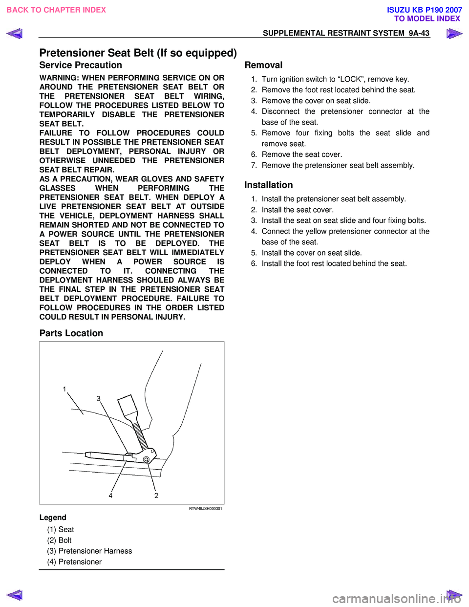
Parts Location
RTW 49JSH000301
Legend
(1) Seat
(2) Bolt
(3) Pretensioner Harness
(4) Pretensioner
Removal
1. Turn ignition switch to “LOCK”, remove key.
2. Remove the foot rest located behind the seat.
3. Remove the cover on seat slide.
4. Disconnect the pretensioner connector at the base of the seat.
5. Remove four fixing bolts the seat slide and remove seat.
6. Remove the seat cover.
7. Remove the pretensioner seat belt assembly.
Installation
1. Install the pretensioner seat belt assembly.
2. Install the seat cover.
3. Install the seat on seat slide and four fixing bolts.
4. Connect the yellow pretensioner connector at the base of the seat.
5. Install the cover on seat slide.
6. Install the foot rest located behind the seat.
BACK TO CHAPTER INDEX TO MODEL INDEXISUZU KB P190 2007
Page 5852 of 6020
IMMOBILIZER CONTROL SYSTEM (4JK1/4JJ1/HFV6)TABLE OF CONTENTS
Schematic and Routing Diagrams. . . . . . . . . . . . 11A-2Immobilizer Controls Schematics . . . . . . . . . . . 11A-2
Component Locator. . . . . . . . . . . . . . . . . . . . . . . 11A-6 Immobilizer Controls Component View . . . . . . 11A-6
Immobilizer Control Unit (ICU) Connector End View . . . . . . . . . . . . . . . . . . . . . . . . . . . . . 11A-7
Diagnostic Information and Procedures . . . . . . . 11A-8 Diagnostic Starting Point - Immobilizer Controls . . . . . . . . . . . . . . . . . . . . . . . . . . . . . . 11A-8
Diagnostic System Check - Immobilizer Controls . . . . . . . . . . . . . . . . . . . . . . . . . . . . . . 11A-8
Scan Tool Data List . . . . . . . . . . . . . . . . . . . . 11A-10
Scan Tool Data Definitions . . . . . . . . . . . . . . . 11A-10
Scan Tool Does Not Power Up. . . . . . . . . . . . 11A-12
Scan Tool Does Not Communicate with CAN Device. . . . . . . . . . . . . . . . . . . . . . . . . . 11A-13
Lost Communication with The Immobilizer Control Unit (ICU) . . . . . . . . . . . . . . . . . . . . . 11A-19
Diagnostic Trouble Code (DTC) List . . . . . . . 11A-21
DTC B0001 . . . . . . . . . . . . . . . . . . . . . . . . . . 11A-22
DTC B0002 . . . . . . . . . . . . . . . . . . . . . . . . . . 11A-23
DTC B0003 . . . . . . . . . . . . . . . . . . . . . . . . . . 11A-24
DTC B0004 . . . . . . . . . . . . . . . . . . . . . . . . . . 11A-26
DTC B0007 . . . . . . . . . . . . . . . . . . . . . . . . . . 11A-27
DTC B0008 . . . . . . . . . . . . . . . . . . . . . . . . . . 11A-28
DTC B0009 . . . . . . . . . . . . . . . . . . . . . . . . . . 11A-29
DTC B0010 . . . . . . . . . . . . . . . . . . . . . . . . . . 11A-30
DTC B0012 . . . . . . . . . . . . . . . . . . . . . . . . . . 11A-32
DTC B0013 . . . . . . . . . . . . . . . . . . . . . . . . . . 11A-33
DTC B0014 . . . . . . . . . . . . . . . . . . . . . . . . . . 11A-34
DTC U0100 . . . . . . . . . . . . . . . . . . . . . . . . . . 11A-35
Resetting and Programming . . . . . . . . . . . . . . . 11A-36 Resetting and Programming Guidelines . . . . 11A-36
Transponder Key Erasing Procedure . . . . . . . 11A-38
Transponder Key Programming Procedure . . 11A-38
ICU Resetting Procedure . . . . . . . . . . . . . . . . 11A-39
ICU Programming Procedure . . . . . . . . . . . . . 11A-39
ECM Resetting Procedure . . . . . . . . . . . . . . . 11A-39
ECM Programming Procedure . . . . . . . . . . . . 11A-40
PIM Resetting Procedure . . . . . . . . . . . . . . . . 11A-40
PIM Programming Procedure. . . . . . . . . . . . . 11A-40
ICU & PIM Programming Procedure . . . . . . . 11A-41
ECM & PIM Programming Procedure . . . . . . 11A-41
ICU & ECM Programming Procedure . . . . . . 11A-42
ICU, ECM & PIM Programming Procedure . . 11A-42
Repair Instructions . . . . . . . . . . . . . . . . . . . . . . 11A-44 Immobilizer Control Unit (ICU) Replacement . . . . . . . . . . . . . . . . . . . . . . . . . 11A-44
Description and Operation . . . . . . . . . . . . . . . . 11A-45 Immobilizer System Description . . . . . . . . . . . 11A-45
Immobilizer System Componenet Description . . . . . . . . . . . . . . . . . . . . . . . . . . 11A-45 Special Tools and Equipment . . . . . . . . . . . . . . 11A-47
Special Tools and Equipment . . . . . . . . . . . . . 11A-47
IM MOBI LIZER CONTR OL SY STEM (4JK 1/4 JJ1/ HFV 6) 1 1A- 1
BACK TO CHAPTER INDEX
TO MODEL INDEX
ISUZU KB P190 2007
Page 5859 of 6020
11A-8 IMMOBILIZER CONTROL SYSTEM (4JK1/4JJ1/HFV6)
Diagnostic Information and Procedures
Diagnostic Starting Point - Immobilizer
Controls
Begin the system diagnosis with Diagnostic System
Check - Immobilizer Controls. The Diagnostic System
Check - Immobilizer Controls will provide the following
information:
• The identification of the control modules which command the system.
• The ability of the control modules to communicate through the serial data circuit.
• The identification of any stored diagnostic trouble codes (DTCs) and the their statuses.
The use of the Diagnostic System Check - Immobilizer
Controls will identify the correct procedure for
diagnosing the system and where the procedure is
located.
Diagnostic System Check - Immobilizer
Controls
Description
The Diagnostic System Check - Immobilizer Controls is
an organized approach to identifying a condition that is
created by a malfunction in the electronic immobilizer
control system. The Diagnostic System Check must be
the starting point for any immobilizer system concern.
The Diagnostic System Check directs the service
technician to the next logical step in order to diagnose
the concern. Understanding and correctly using the
diagnostic table reduces diagnostic time, and prevents
the replacement of good parts. Test Description
The numbers below refer to the step numbers on the
diagnostic table.
2. Lack of communication may be because of a partial
or a total malfunction of the serial data circuit.
6. The presence of DTCs which begin with U, indicate
that some other module is not communicating.
9. If there are other modules with DTCs set, refer to the
DTC list. The DTC list directs you to the appropriate
diagnostic procedure.
Important: • DO NOT perform this diagnostic if there is not an immobilizer system concern, unless another
procedure directs you to this diagnostic.
• Before you proceed with diagnosis, search for applicable service bulletins.
• Unless a diagnostic procedure instructs you, DO NOT clear the DTCs.
• Ensure the battery has a full charge.
• Ensure the battery cables (+) (-) are clean and tight.
• Ensure the ICU ground is clean, tight, and in the correct location.
• Ensure the ICU harness connector is clean and correctly connected.
• Ensure the ICU terminals are clean and correctly mating.
• Ensure the immobilizer security information is correctly programmed into the ICU, ECM and PIM.
• Ensure the ICU is correctly installed to the steering lock.
• Ensure objects does not block transponder key in the steering lock.
• Ensure another transponder key is not attached to the key ring.
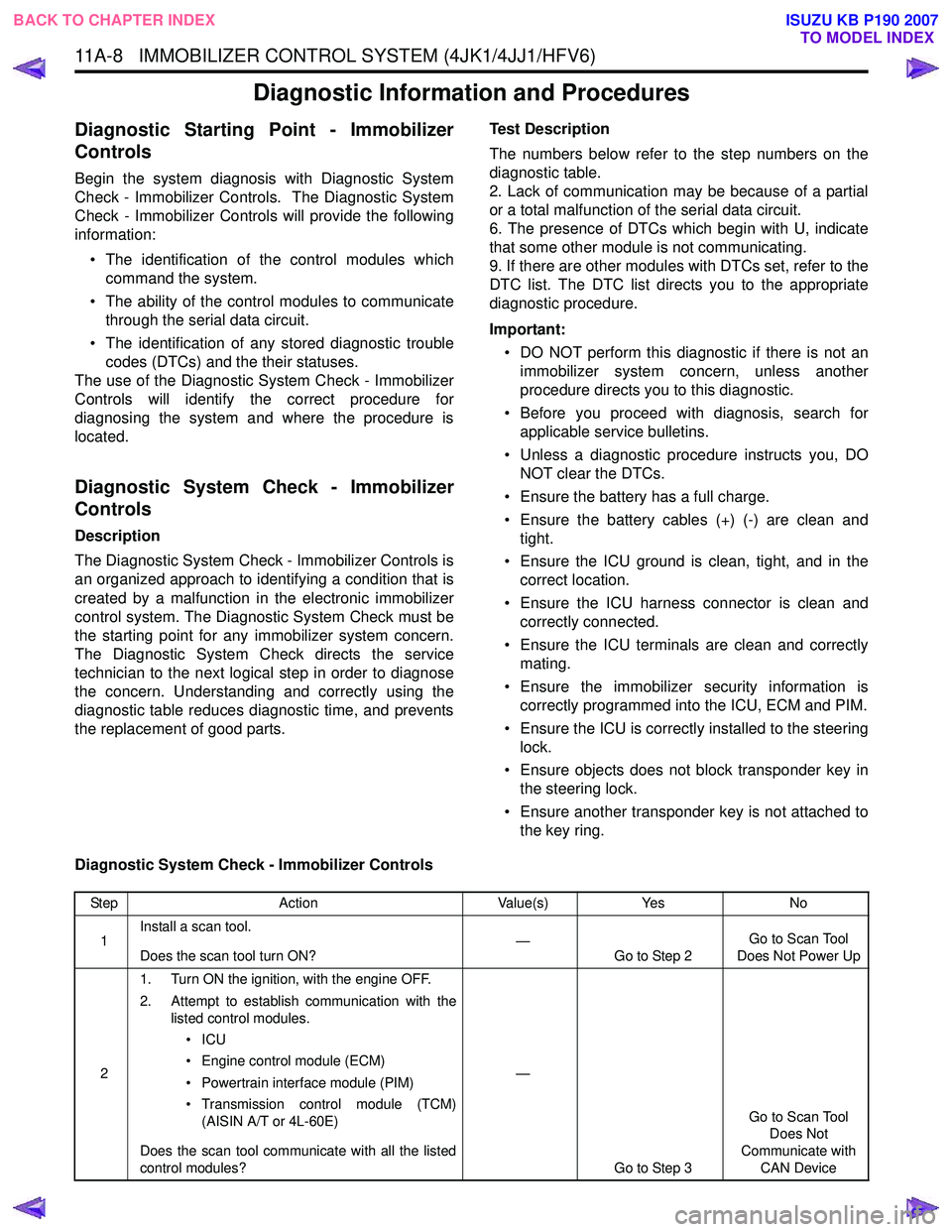
Diagnostic System Check - Immobilizer Controls
Step Action Value(s)Yes No
1 Install a scan tool.
Does the scan tool turn ON? —
Go to Step 2 Go to Scan Tool
Does Not Power Up
2 1. Turn ON the ignition, with the engine OFF.
2. Attempt to establish communication with the listed control modules.
•ICU
• Engine control module (ECM)
• Powertrain interface module (PIM)
• Transmission control module (TCM) (AISIN A/T or 4L-60E)
Does the scan tool communicate with all the listed
control modules? —
Go to Step 3 Go to Scan Tool
Does Not
Communicate with CAN Device
BACK TO CHAPTER INDEX TO MODEL INDEX
ISUZU KB P190 2007