2007 ISUZU KB P190 oil
[x] Cancel search: oilPage 3784 of 6020
Automatic Transmission – 4L60E – General Information Page 7C1–24
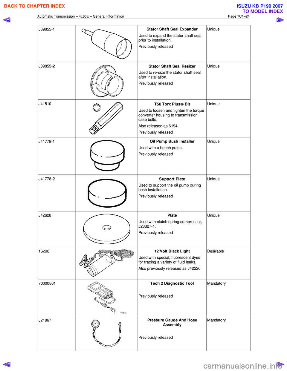
J39855-1
Stator Shaft Seal Expander
Used to expand the stator shaft seal
prior to installation.
Previously released Unique
J39855-2
Stator Shaft Seal Resizer
Used to re-size the stator shaft seal
after installation.
Previously released Unique
J41510
T50 Torx Plus
Bit
Used to loosen and tighten the torque
converter housing to transmission
case bolts.
Also released as 6194.
Previously released Unique
J41778-1
Oil Pump Bush Installer
Used with a bench press.
Previously released Unique
J41778-2
Support Plate
Used to support the oil pump during
bush installation.
Previously released Unique
J42628
Plate
Used with clutch spring compressor,
J23327-1.
Previously released Unique
16296 12 Volt Black Light
Used with special, fluorescent dyes
for tracing a variety of fluid leaks.
Also previously released as J42220 Desirable
70000861
Tech 2 Diagnostic Tool
Previously released Mandatory
J21867
Pressure Gauge And Hose
Assembly
Previously released Mandatory
BACK TO CHAPTER INDEX
TO MODEL INDEX
ISUZU KB P190 2007
Page 3785 of 6020
Automatic Transmission – 4L60E – General Information Page 7C1–25
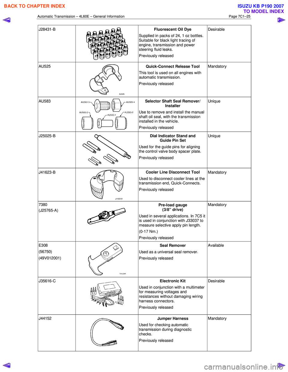
J28431-B
Fluorescent Oil Dye
Supplied in packs of 24, 1 oz bottles.
Suitable for black light tracing of
engine, transmission and power
steering fluid leaks.
Previously released Desirable
AU525
AU525 Quick-Connect Release Tool
This tool is used on all engines with
automatic transmission.
Previously released Mandatory
AU583 Selector Shaft Seal Remover/
Installer
Use to remove and install the manual
shaft oil seal, with the transmission
installed in the vehicle.
Previously released Unique
J25025-B
Dial Indicator Stand and
Guide Pin Set
Used for the guide pins for aligning
the control valve body spacer plate.
Previously released Unique
J41623-B
Cooler Line Disconnect Tool
Used to disconnect cooler lines at the
transmission end, Quick-Connects.
Previously released Mandatory
7380
(J25765-A)
Pre-load gauge
(3/8” drive)
Used in several applications. In 7C5 it
is used in conjunction with J33037 to
measure selective apply pin length.
(0-17 Nm.)
Previously released Mandatory
E308
(56750)
(49V012001)
Seal Remover
Used as a universal seal remover .
Previously released Available
J35616-C
Electronic Kit
Used in conjunction with a multimeter
for measuring voltages and
resistances without damaging wiring
harness connectors.
Previously released Desirable
J44152
Jumper Harness
Used for checking automatic
transmission during diagnostic
checks.
Previously released Mandatory
BACK TO CHAPTER INDEX
TO MODEL INDEX
ISUZU KB P190 2007
Page 3819 of 6020
Automatic Transmission – 4L60E – Electrical Diagnosis Page 7C2–33
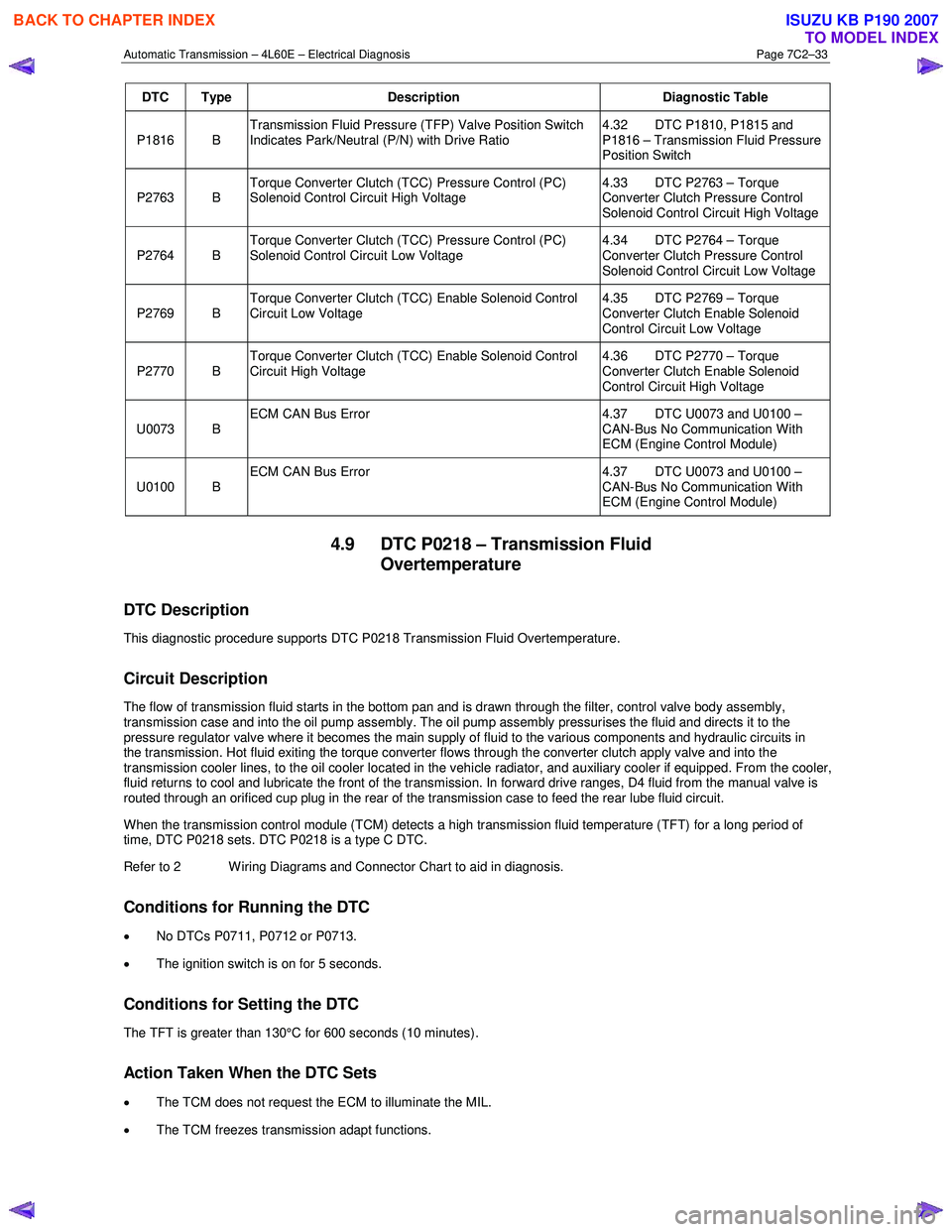
DTC Type Description Diagnostic Table
P1816 B Transmission Fluid Pressure (TFP) Valve Position Switch
Indicates Park/Neutral (P/N) with Drive Ratio 4.32 DTC P1810, P1815 and
P1816 – Transmission Fluid Pressure
Position Switch
P2763 B Torque Converter Clutch (TCC) Pressure Control (PC)
Solenoid Control Circuit High Voltage 4.33 DTC P2763 – Torque
Converter Clutch Pressure Control
Solenoid Control Circuit High Voltage
P2764 B Torque Converter Clutch (TCC) Pressure Control (PC)
Solenoid Control Circuit Low Voltage 4.34 DTC P2764 – Torque
Converter Clutch Pressure Control
Solenoid Control Circuit Low Voltage
P2769 B Torque Converter Clutch (TCC) Enable Solenoid Control
Circuit Low Voltage 4.35 DTC P2769 – Torque
Converter Clutch Enable Solenoid
Control Circuit Low Voltage
P2770 B Torque Converter Clutch (TCC) Enable Solenoid Control
Circuit High Voltage 4.36 DTC P2770 – Torque
Converter Clutch Enable Solenoid
Control Circuit High Voltage
U0073 B ECM CAN Bus Error
4.37 DTC U0073 and U0100 –
CAN-Bus No Communication With
ECM (Engine Control Module)
U0100 B ECM CAN Bus Error
4.37 DTC U0073 and U0100 –
CAN-Bus No Communication With
ECM (Engine Control Module)
4.9 DTC P0218 – Transmission Fluid Overtemperature
DTC Description
This diagnostic procedure supports DTC P0218 Transmission Fluid Overtemperature.
Circuit Description
The flow of transmission fluid starts in the bottom pan and is drawn through the filter, control valve body assembly,
transmission case and into the oil pump assembly. The oil pump assembly pressurises the fluid and directs it to the
pressure regulator valve where it becomes the main supply of fluid to the various components and hydraulic circuits in
the transmission. Hot fluid exiting the torque converter flows through the converter clutch apply valve and into the
transmission cooler lines, to the oil cooler located in the vehicle radiator, and auxiliary cooler if equipped. From the cooler ,
fluid returns to cool and lubricate the front of the transmission. In forward drive ranges, D4 fluid from the manual valve is
routed through an orificed cup plug in the rear of the transmission case to feed the rear lube fluid circuit.
When the transmission control module (TCM) detects a high transmission fluid temperature (TFT) for a long period of
time, DTC P0218 sets. DTC P0218 is a type C DTC.
Refer to 2 W iring Diagrams and Connector Chart to aid in diagnosis.
Conditions for Running the DTC
• No DTCs P0711, P0712 or P0713.
• The ignition switch is on for 5 seconds.
Conditions for Setting the DTC
The TFT is greater than 130°C for 600 seconds (10 minutes).
Action Taken When the DTC Sets
•
The TCM does not request the ECM to illuminate the MIL.
• The TCM freezes transmission adapt functions.
BACK TO CHAPTER INDEX
TO MODEL INDEX
ISUZU KB P190 2007
Page 3843 of 6020
Automatic Transmission – 4L60E – Electrical Diagnosis Page 7C2–57
Step Action Yes No
3 Test the stop lamp switch assembly, refer to 8B Cruise Control.
Is the stop lamp switch assembly serviceable? Go to Step 4 Replace the stop
lamp switch assembly
4 1 Disconnect connector C-96 from the TCM.
2 Using a multimeter set to measure voltage, probe between harness connector C-96 pin 42 and a known ground.
3 Press the brake pedal.
Does the multimeter display battery voltage? Go to Step 5 Repair or replace
affected circuit
Go to Step 6
5 Replace the TCM, refer to 7C4 Automatic Transmission – 4L60E –
On-vehicle Servicing.
Did you complete the replacement? Go to Step 6 —
6 Perform the following procedure to verify the repair:
1 On Tech 2 select: Diagnostic Trouble Codes / Clear Engine & Transmission
DTCs.
2 Follow the instructions on Tech 2 and clear any DTCs.
3 Operate the vehicle under the following conditions:
• Turn on the ignition, with the engine off for at least
2 seconds.
• Start the vehicle and idle for 5 seconds.
• Drive in D4 from 0 – 60 km/h then brake, eight times in one
ignition cycle.
4 On Tech 2 select:
Diagnostic Trouble Codes / Read DTC Information.
Has DTC P0724 set? Go to Step 2 Go to Step 7
7 On Tech 2 select:
Diagnostic Trouble Codes / Read DTC Information.
Does Tech 2 display any DTCs you have not diagnosed? Refer to
4.8 Diagnostic Trouble Code List System OK
When all diagnosis and repairs are completed, check the
system for correct operation.
4.18 DTC P0741 – Torque Converter Clutch
System – Stuck Off
DTC Description
This diagnostic procedure supports DTC P0741 Torque Converter Clutch (TCC) System - Stuck Off.
Circuit Description
The torque converter clutch (TCC) solenoid valve is a normally-open exhaust valve that is used with the torque converter
clutch pulse width modulation (TCC PWM) solenoid valve to control fluid acting on the converter clutch apply valve. The
TCC solenoid valve attaches to the transmission case assembly extending into the pump cover. W hen grounded by the
transmission control module (TCM), the TCC solenoid valve stops converter signal oil from exhausting. This causes
converter signal oil pressure to increase and move the converter clutch apply valve against spring force and into the
apply position. In this position, release fluid is open to an exhaust port and converter feed fluid fills the apply fluid circu it.
The converter feed fluid applies the TCC. When the TCM no longer provides a ground path, the TCC solenoid valve de-
energizes and apply fluid exhausts, releasing the TCC.
When the TCM detects high torque converter slip when the TCC is commanded off, then DTC P0741 sets. DTC P0741 is
a type B DTC.
Refer to 2 W iring Diagrams and Connector Chart to aid in diagnosis.
BACK TO CHAPTER INDEX
TO MODEL INDEX
ISUZU KB P190 2007
Page 3846 of 6020
Automatic Transmission – 4L60E – Electrical Diagnosis Page 7C2–60
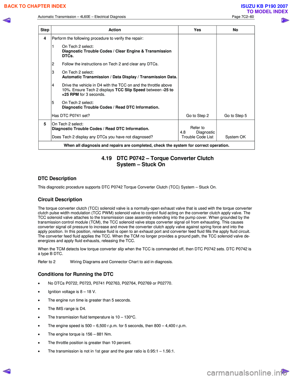
Step Action Yes No
4 Perform the following procedure to verify the repair:
1 On Tech 2 select: Diagnostic Trouble Codes / Clear Engine & Transmission
DTCs.
2 Follow the instructions on Tech 2 and clear any DTCs.
3 On Tech 2 select: Automatic Transmission / Data Display / Transmission Data.
4 Drive the vehicle in D4 with the TCC on and the throttle above 10%. Ensure Tech 2 displays TCC Slip Speed between -25 to
+25 RPM for 3 seconds.
5 On Tech 2 select:
Diagnostic Trouble Codes / Read DTC Information.
Has DTC P0741 set? Go to Step 2 Go to Step 5
5 On Tech 2 select:
Diagnostic Trouble Codes / Read DTC Information.
Does Tech 2 display any DTCs you have not diagnosed? Refer to
4.8 Diagnostic Trouble Code List System OK
When all diagnosis and repairs are completed, check the system for correct operation.
4.19 DTC P0742 – Torque Converter Clutch
System – Stuck On
DTC Description
This diagnostic procedure supports DTC P0742 Torque Converter Clutch (TCC) System – Stuck On.
Circuit Description
The torque converter clutch (TCC) solenoid valve is a normally-open exhaust valve that is used with the torque converter
clutch pulse width modulation (TCC PWM) solenoid valve to control fluid acting on the converter clutch apply valve. The
TCC solenoid valve attaches to the transmission case assembly extending into the pump cover. W hen grounded by the
transmission control module (TCM), the TCC solenoid valve stops converter signal oil from exhausting. This causes
converter signal oil pressure to increase and move the converter clutch apply valve against spring force and into the
apply position. In this position, release fluid is open to an exhaust port and converter feed fluid fills the apply fluid circu it.
The converter feed fluid applies the TCC. When the TCM no longer provides a ground path, the TCC solenoid valve de-
energizes and apply fluid exhausts, releasing the TCC.
W hen the TCM detects low torque converter slip when the TCC is commanded off, then DTC P0742 sets. DTC P0742 is
a type B DTC.
Refer to 2 W iring Diagrams and Connector Chart to aid in diagnosis.
Conditions for Running the DTC
• No DTCs P0722, P0723, P0741 P02763, P02764, P02769 or P02770.
• Ignition voltage is 8 – 18 V.
• The engine run time is greater than 5 seconds.
• The IMS range is D4.
• The transmission fluid temperature is 10 – 130°C.
• The engine speed is 500 – 6,500 r.p.m. for 5 seconds, then 800 – 4,400 r.p.m.
• The engine torque is 156 – 881 Nm.
• The throttle position is greater than 10 percent.
• The transmission is not in 1st gear and the gear ratio is 0.95:1 – 1.56:1.
BACK TO CHAPTER INDEX
TO MODEL INDEX
ISUZU KB P190 2007
Page 3856 of 6020
Automatic Transmission – 4L60E – Electrical Diagnosis Page 7C2–70
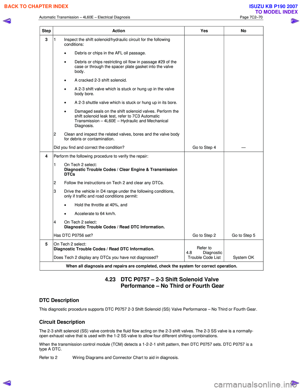
Step Action Yes No
3 1 Inspect the shift solenoid/hydraulic circuit for the following
conditions:
• Debris or chips in the AFL oil passage.
• Debris or chips restricting oil flow in passage #29 of the
case or through the spacer plate gasket into the valve
body.
• A cracked 2-3 shift solenoid.
• A 2-3 shift valve which is stuck or hung up in the valve
body bore.
• A 2-3 shuttle valve which is stuck or hung up in its bore.
• Damaged seals on the shift solenoid valves. Perform the
shift solenoid leak test, refer to 7C3 Automatic
Transmission – 4L60E – Hydraulic and Mechanical
Diagnosis.
2 Clean and inspect the related valves, bores and the valve body for debris or contamination.
Did you find and correct the condition? Go to Step 4 —
4 Perform the following procedure to verify the repair:
1 On Tech 2 select: Diagnostic Trouble Codes / Clear Engine & Transmission
DTCs
2 Follow the instructions on Tech 2 and clear any DTCs.
3 Drive the vehicle in D4 range under the following conditions, only if traffic and road conditions permit:
• Hold the throttle at 40%, and
• Accelerate to 64 km/h.
4 On Tech 2 select:
Diagnostic Trouble Codes / Read DTC Information.
Has DTC P0756 set? Go to Step 2 Go to Step 5
5 On Tech 2 select:
Diagnostic Trouble Codes / Read DTC Information.
Does Tech 2 display any DTCs you have not diagnosed? Refer to
4.8 Diagnostic Trouble Code List System OK
When all diagnosis and repairs are completed, check the system for correct operation.
4.23 DTC P0757 – 2-3 Shift Solenoid Valve
Performance – No Third or Fourth Gear
DTC Description
This diagnostic procedure supports DTC P0757 2-3 Shift Solenoid (SS) Valve Performance – No Third or Fourth Gear.
Circuit Description
The 2-3 shift solenoid (SS) valve controls the fluid flow acting on the 2-3 shift valves. The 2-3 SS valve is a normally-
open exhaust valve that is used with the 1-2 SS valve to allow four different shifting combinations.
When the transmission control module (TCM) detects a 1-2-2-1 shift pattern, then DTC P0757 sets. DTC P0757 is a
type A DTC.
Refer to 2 W iring Diagrams and Connector Chart to aid in diagnosis.
BACK TO CHAPTER INDEX
TO MODEL INDEX
ISUZU KB P190 2007
Page 3867 of 6020
Automatic Transmission – 4L60E – Electrical Diagnosis Page 7C2–81
Action Taken When the DTC Sets
• The TCM requests the ECM to illuminate the MIL during the second consecutive trip in which the conditions for
setting the DTC are met.
• The TCM commands maximum line pressure.
• The TCM freezes transmission adaptive functions.
• The TCM inhibits TCC.
• The TCM inhibits 4th gear if in hot mode.
• At the time of the first failure, the TCM records the operating conditions when the conditions for setting the DTC are
met. The TCM stores this information as a Failure Record.
• At the time of the second failure, the ECM records the operating conditions when the conditions for setting the DTC
are met. The ECM stores this information as a Freeze Frame.
• The TCM stores DTC P0894 in TCM history during the second consecutive trip in which the conditions for setting
the DTC are met.
Conditions for Clearing the DTC
• The ECM turns off the MIL after the fourth consecutive drive trip in which the TCM does not send a MIL illumination
request.
• Tech 2 can clear the DTC.
• The TCM clears the DTC from TCM history if the vehicle completes 40 warm-up cycles without a non-emission
related diagnostic fault occurring.
• The TCM cancels the DTC default actions when the ignition is off long enough to power down the TCM.
Diagnostic Aids
•
Bronze material found in the transmission oil pan may indicate stator shaft bushing wear. If bushing wear is
suspected, inspect the stator shaft and the input, turbine, shaft for damage.
• Perform the Torque Converter Diagnosis Procedure, refer to 7C3 Automatic Transmission – 4L60E – Hydraulic and
Mechanical Diagnosis.
Test Description
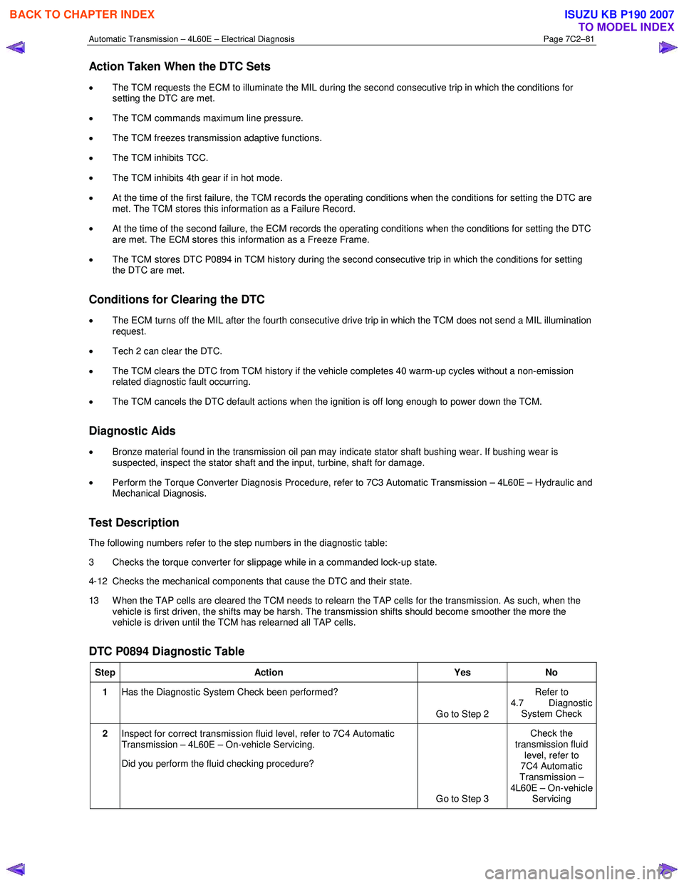
The following numbers refer to the step numbers in the diagnostic table:
3 Checks the torque converter for slippage while in a commanded lock-up state.
4-12 Checks the mechanical components that cause the DTC and their state.
13 W hen the TAP cells are cleared the TCM needs to relearn the TAP cells for the transmission. As such, when the vehicle is first driven, the shifts may be harsh. The transmission shifts should become smoother the more the
vehicle is driven until the TCM has relearned all TAP cells.
DTC P0894 Diagnostic Table
Step Action Yes No
1 Has the Diagnostic System Check been performed?
Go to Step 2 Refer to
4.7 Diagnostic System Check
2 Inspect for correct transmission fluid level, refer to 7C4 Automatic
Transmission – 4L60E – On-vehicle Servicing.
Did you perform the fluid checking procedure?
Go to Step 3 Check the
transmission fluid level, refer to
7C4 Automatic
Transmission –
4L60E – On-vehicle Servicing
BACK TO CHAPTER INDEX
TO MODEL INDEX
ISUZU KB P190 2007
Page 3869 of 6020
Automatic Transmission – 4L60E – Electrical Diagnosis Page 7C2–83
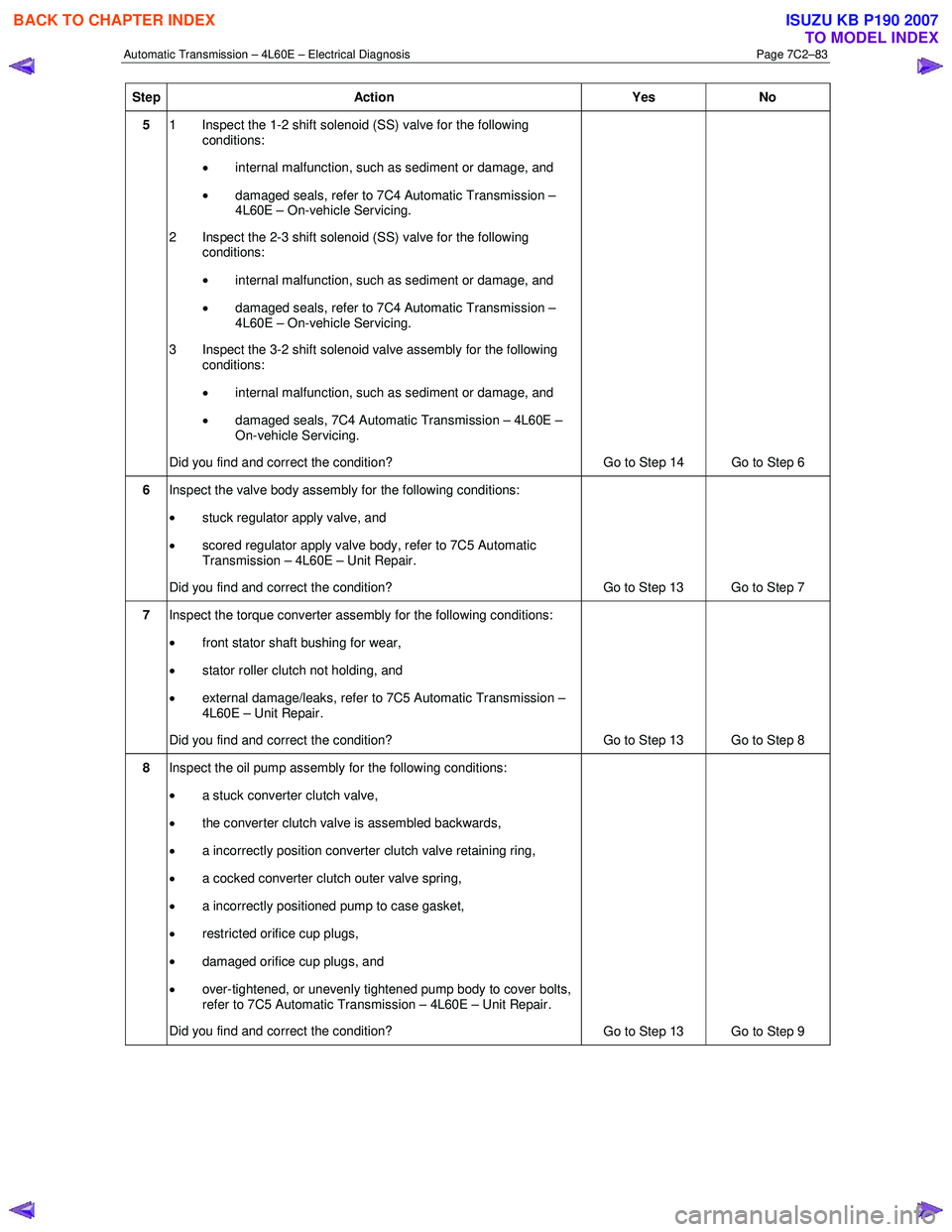
Step Action Yes No
5 1 Inspect the 1-2 shift solenoid (SS) valve for the following
conditions:
• internal malfunction, such as sediment or damage, and
• damaged seals, refer to 7C4 Automatic Transmission –
4L60E – On-vehicle Servicing.
2 Inspect the 2-3 shift solenoid (SS) valve for the following conditions:
• internal malfunction, such as sediment or damage, and
• damaged seals, refer to 7C4 Automatic Transmission –
4L60E – On-vehicle Servicing.
3 Inspect the 3-2 shift solenoid valve assembly for the following conditions:
• internal malfunction, such as sediment or damage, and
• damaged seals, 7C4 Automatic Transmission – 4L60E –
On-vehicle Servicing.
Did you find and correct the condition? Go to Step 14 Go to Step 6
6 Inspect the valve body assembly for the following conditions:
• stuck regulator apply valve, and
• scored regulator apply valve body, refer to 7C5 Automatic
Transmission – 4L60E – Unit Repair.
Did you find and correct the condition? Go to Step 13 Go to Step 7
7 Inspect the torque converter assembly for the following conditions:
• front stator shaft bushing for wear,
• stator roller clutch not holding, and
• external damage/leaks, refer to 7C5 Automatic Transmission –
4L60E – Unit Repair.
Did you find and correct the condition? Go to Step 13 Go to Step 8
8 Inspect the oil pump assembly for the following conditions:
• a stuck converter clutch valve,
• the converter clutch valve is assembled backwards,
• a incorrectly position converter clutch valve retaining ring,
• a cocked converter clutch outer valve spring,
• a incorrectly positioned pump to case gasket,
• restricted orifice cup plugs,
• damaged orifice cup plugs, and
• over-tightened, or unevenly tightened pump body to cover bolts,
refer to 7C5 Automatic Transmission – 4L60E – Unit Repair.
Did you find and correct the condition? Go to Step 13 Go to Step 9
BACK TO CHAPTER INDEX
TO MODEL INDEX
ISUZU KB P190 2007