2007 ISUZU KB P190 oil
[x] Cancel search: oilPage 3765 of 6020
Automatic Transmission – 4L60E – General Information Page 7C1–5
Clean and Inspect
Do not use solvents on neoprene seals,
composition faced clutch plates or thrust
washers as damage to parts may occur.
After complete disassembly of a component, wash all metal parts in a clean solvent and dry with compressed air. Blow
oil passages out and check to make sure they are not obstructed, small passages should be checked with tag wire. All
parts should be inspected to determine if replacement is required.
Pay particular attention to the following:
• Inspect linkage and pivot points for excessive wear.
• Bearing and thrust surfaces of all parts should be checked for excessive wear and scoring.
• Check for broken seal rings, damaged ring lands and damaged threads.
• Inspect seals for damage.
• Mating surfaces of castings should be checked for burrs. Irregularities may be removed by lapping the surface with
emery paper laid on a flat surface, such as a piece of plate glass.
• Castings should be checked for cracks and porosity.
1.3 7C2 Automatic Transmission – 4L60E –
Electrical Diagnosis
For transmissions fitted to V6 engines, the electrical diagnosis is in this Section. A new electrical circuit and control
module has been introduced for automatic transmissions fitted to the V6 engines.
1.4 7C3 Automatic Transmission – 4L60E – Hydraulic and Mechanical Diagnosis
Information contained in 7C3 Automatic Transmission – 4L60E – Hydraulic and Mechanical Diagnosis will assist in the
diagnosis of the mechanical and hydraulic components in the 4L60E automatic transmission, while the transmission
remains installed on the vehicle.
Examples of the type of diagnostic information contained within this section are:
• transmission functional test,
• line pressure information,
• transmission fluid diagnosis,
• symptom diagnosis and
• shift speed charts.
1.5 7C4 Automatic Transmission – 4L60E –
On-vehicle Servicing
Information in 7C4 Automatic Transmission – 4L60E – On-vehicle Servicing covers transmission fluid level checking, as
well as specific information for servicing some components while the transmission remains installed on the vehicle. This
Section also covers the transmission removal and reinstallation to the vehicle.
BACK TO CHAPTER INDEX
TO MODEL INDEX
ISUZU KB P190 2007
Page 3768 of 6020
Automatic Transmission – 4L60E – General Information Page 7C1–8
2.4 System Protection Devices
Should 1st gear be selected and left in that range, the TCM will protect the engine from an over-speeding condition by
upshifting to 2nd gear at a pre-determined point. Similarly, the TCM provides high speed, downshift protection by
preventing a manual shift into 1st gear above pre-determined engine speeds.
Under severe operating conditions such as towing in high ambient temperatures, fluid temperatures can rise to a point
where lubrication breakdown can occur. In addition to having an oil cooler fitted to the vehicle, the 4L60E transmission is
also fitted with a transmission fluid temperature sensor located in the Transmission Range (TR) Pressure Switch
Assembly (PSA).
When fluid temperatures in excess of 135 °C are sensed, the torque converter clutch is applied as programmed, in 3rd or
4th gear. This action reduces further the fluid temperature during normal operation of the torque converter. While these
high fluid temperatures are sensed however, torque converter clutch apply is not available when the throttle opening is
above 50%.
Similarly, when the fluid temperature is below 29 °C, the TCM prevents torque converter clutch apply.
If a condition occurs, preventing electronic control of the transmission's functions, a 'Fail Safe' mode will default the
transmission to 3rd gear when either Drive or 3 is selected, applying also maximum line pressure. W hile in this mode, the
vehicle operator can still manually select 2, 1, Reverse, Park or Neutral, should the need arise.
2.5 Self Diagnosis
If any transmission operation controlled by the TCM begins to operate outside its pre-set parameters, the TCM has the
ability to store a range of diagnostic codes which can be accessed by the servicing technician, thereby localising the
problem.
2.6 TCM Sensors and Actuators
As indicated earlier, there are a number of sensors and switches providing input information for the TCM programming
that will allow the TCM to change the shift pattern, shift feel and torque converter clutch operation.
The TCM does this by comparing this input information with its predetermined values on shift pattern, fluid pressure
maps, shift duration parameters, extreme heat protection programming and adaptive controls.
In addition, each input signal and output actuator operation is also monitored and if outside its pre-set parameters, a
diagnostic code is logged for future reference by the servicing technician.
BACK TO CHAPTER INDEX
TO MODEL INDEX
ISUZU KB P190 2007
Page 3772 of 6020
Automatic Transmission – 4L60E – General Information Page 7C1–12
General Definition
Check Ball A spherical, hydraulically controlled component (usually of steel) that either seals or
opens fluid circuits. It is also referred to as a check valve.
Clutch Pack An assembly of components generally consisting of clutch plates, an apply plate and a
backing plate.
Clutch Plate A hydraulically activated component that has two basic designs: (1) all steel, or (2) a
steel core with friction material bonded to one or two sides of the plate.
Control Valve Body A machined metal casting that contains valve trains and other hydraulically controlled components that shift the transmission.
Coupling Speed The speed at which a vehicle is travelling and no longer requires torque multiplication through the torque converter. At this point, the stator 'free wheels' to allow fluid leaving
the turbine to flow directly to the pump. (Also see Torque Converter).
De-energise(d) To interrupt the electrical current that flows to an electronically controlled device,
making it electrically inoperable.
Direct Drive A condition in a gears set where the input speed and input torque equals the output
speed and output torque. The gear ratio through the gear set is 1:1.
Downshift A change in a gear ratio where both input speed and torque increases.
Duty Cycle In reference to an electronically controlled solenoid, it is the amount of time (expressed
as a percentage) that current flows through the solenoid coil.
Energise(d) To supply a current to an electronically controlled device, enabling it to perform its
designed function.
Engine Compression Braking A condition where compression from the engine is used with the transmission to decrease vehicle speed.
Exhaust The release of fluid pressure from a hydraulic circuit. (The words 'exhausts' and
'exhausting' are also used and have the same intended meaning.)
Fail-safe Mode A condition whereby a component (i.e. engine or transmission) will partially function even if its electrical circuit is disabled.
Fluid In this Section of the Service Manual, 'fluid' refers primarily to automatic transmission
fluid (or ATF) and, for the Hydra-matic 4L60E transmission, the only recommended
fluid is Dexron
III.
Fluid Pressure A pressure that is consistent throughout a given fluid circuit.
Force A measurable effort that is exerted on an object (component).
Freewheeling A condition where power is lost through a driving or holding device (i.e. roller or sprag
clutches).
Friction Material A heat and wear resistant fibrous material, bonded to clutch plates and bands.
Gear A round, toothed device that is used for transmitting torque through other components.
Gear Range A specific speed to torque ratio at which the transmission is operating (i.e. 1st gear,
2nd gear etc.).
Gear Ratio Revolutions of an input gear as compared to the revolutions of an output gear. It can
also be expressed as the number of teeth on a gear as compared to the number of
teeth on a gear that it is in mesh with.
Hydraulic Circuit A fluid passage which often includes the mechanical components in that circuit
designed to perform a specific function.
Input A starting point for torque, revolutions or energy into another component of the
transmission.
Internal Gear The outermost member of a gear set that has gear teeth in constant mesh with the
planetary pinion gears of the gear set.
Land (Valve Land) The larger diameters of a spool valve that contact the valve bore or bushing.
BACK TO CHAPTER INDEX
TO MODEL INDEX
ISUZU KB P190 2007
Page 3775 of 6020

Automatic Transmission – 4L60E – General Information Page 7C1–15
5 Service Notes
In the interests of safety to personnel, equipment and to the vehicle and its components, read and adhere to the following
notes whenever servicing operations are to be carried out on the Hydra-matic 4L60E automatic transmission. In addition,
some of this information also refers to sound workshop practices and, to achieve the design life of affected components.
Fasteners
• Always reinstall fasteners in the same locations as they were removed.
• If a fastener requires replacement, always use a part of the correct part number or of equal size and strength or
stronger.
General Workshop Practice
• Keep work area and tools clean.
• To avoid unnecessary contamination, always clean the exterior of the transmission before removing any parts.
• Do not use wiping cloths or rags because of the risk of lint being trapped in the transmission.
• Do not use solvents on:
• neoprene seals,
• composition faced clutch plates, or
• thrust washers.
• Always wear eye protection when using compressed air.
• Blow out all passages with compressed air. Only probe small passages with soft, thin wire.
• Handle parts with care to avoid nicks and scratches.
• Do not remove Teflon oil seal rings unless damaged or performing a complete overhaul.
• Expand internal snap rings and compress external snap rings to maximise retention and security.
• Lubricate all internal parts with transmission fluid (only use Dexron® III), as they are being installed.
• When installing cap screws into aluminium castings:
• always use a torque wrench and
• stripped or damaged threads in aluminium castings may be reconditioned by using commercially available
thread inserts.
• Once removed, replace all gaskets, seals and O-rings with new parts.
• Always use seal protectors where indicated and do not use gasket cement or sealant on any joined face unless
specified to do so.
BACK TO CHAPTER INDEX
TO MODEL INDEX
ISUZU KB P190 2007
Page 3776 of 6020
Automatic Transmission – 4L60E – General Information Page 7C1–16
6 Torque Specifications
Oil pan attaching bolt ............................................................................ 12.0 Nm
Shift selector base plate attaching nut ................................................... 7.0 Nm
Spring plate attaching screw .................................................................. 2.0 Nm
Selector lever knob attaching screw ....................................................... 2.0 Nm
Selector cable bracket attaching bolt.................................................... 22.0 Nm
Heat shield front attaching screw .............................................. 15.0 – 35.0 Nm
Heat shield rear attaching screw ............................................................ 9.0 Nm
Manual shaft linkage attaching nut ...................................................... 25.0 Nm
Neutral start and back-up lamp switch attaching screw............. 15.0 – 35.0 Nm
Vehicle speed sensor attaching bolt ........................................... 11.0 - 14.0 Nm
Transmission mount attaching bolt ...................................................... 50.0 Nm
Transmission support attaching bolt and nut ............................. 50.0 – 65.0 Nm
Transmission mount attaching nut ....................................................... 52.0 Nm
Heat shield to transmission support attaching bolt ............................... 52.0 Nm
Extension housing attaching bolt ............................................... 42.0 – 48.0 Nm
1 – 2 Accumulator cover attaching bolt................................................. 12.0 Nm
TCC solenoid attaching bolt ................................................................. 12.0 Nm
Control valve body attaching bolt ......................................................... 12.0 Nm
Transmission fluid pressure (TFP) manual valve
position switch attaching bolt ................................................................ 12.0 Nm
Manual detent spring attaching bolt ...................................................... 23.0 Nm
Spacer plate support plate attaching bolt ............................................. 12.0 Nm
Filler tube bracket attaching bolt................................................ 20.0 – 35.0 Nm
Vent pipe attaching bolt .......................................................................... 6.0 Nm
Transmission cooler lines bracket attaching screw .............................. 23.0 Nm
Torque converter housing attaching bolt ................................... 52.0 – 66.0 Nm
Torque converter to flexplate attaching bolt............................... 60.0 – 70.0 Nm
Torque converter cover attaching bolt ....................................... 12.0 – 16.0 Nm
TCM bracket attaching nut ..................................................................... 7.0 Nm
TCM attaching bolt and nut .................................................................... 7.0 Nm
Oil Pump Cover to Pump Body Attaching Bolt...................................... 25.0 Nm
Pressure Control Solenoid Retainer Attaching Bolt .............................. 12.0 Nm
Forward Accumulator Cover Attaching Bolt .......................................... 12.0 Nm
Oil Pump to Transmission Case Attaching Bolt .................................... 30.0 Nm
Torque Converter Housing to
Transmission Case Attaching Bolt............................................. 65.0 – 75.0 Nm
BACK TO CHAPTER INDEX
TO MODEL INDEX
ISUZU KB P190 2007
Page 3777 of 6020
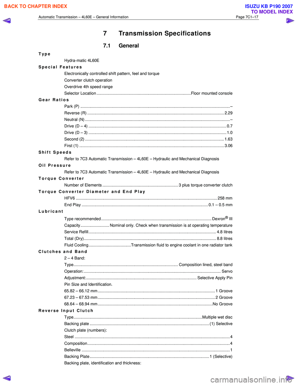
Automatic Transmission – 4L60E – General Information Page 7C1–17
7 Transmission Specifications
7.1 General
Type
Hydra-matic 4L60E
Special Features
Electronically controlled shift pattern, feel and torque
Converter clutch operation
Overdrive 4th speed range
Selector Location ..................................................................................Floor mounted console
Gear Ratios Park (P) ....................................................................................................................... ........... –
Reverse (R) .................................................................................................................... ... 2.29
Neutral (N) .............................................................................................................................. –
Drive (D – 4) .................................................................................................................. ...... 0.7
Drive (D – 3) .................................................................................................................. ...... 1.0
Second (2) ......................................................................................................................... 1.63
First (1) ...................................................................................................................... ........ 3.06
Shift Speeds Refer to 7C3 Automatic Transmission – 4L60E – Hydraulic and Mechanical Diagnosis
Oil Pressure
Refer to 7C3 Automatic Transmission – 4L60E – Hydraulic and Mechanical Diagnosis
Torque Converter
Number of Elements .................................................................. 3 plus torque converter clutch
Torque Converter Diameter and End Play
HFV6 ........................................................................................................................... 258 mm
End Play .............................................................................................................. 0.1 – 0.5 mm
Lubricant
Type recommended ................................................................................................ Dexron
® III
Capacity......................... Nominal only. Check when transmission is at operating temperature
Service Refill ............................................................................................................... 4. 8 litres
Total (Dry)................................................................................................................... 8 .8 litres
Fluid Cooling.....................................Transmission fluid to engine coolant in one radiator tank
Clutches and Band 2 – 4 Band:
Type........................................................................................... Composition lined, steel band
Operation: ..................................................................................................................... .. Servo
Adjustment: ................................................................................................ Selective Apply Pin
Pin Size and Identification.
65.82 – 66.12 mm ...................................................................................................... 1 Groove
67.23 – 67.53 mm ...................................................................................................... 2 Groove
68.64 – 68.94 mm ....................................................................................................No Groove
Reverse Input Clutch Type................................................................................................................Multiple we t disc
Backing plate ........................................................................................................ (1) Select ive
Clutch plate (numbers):
Steel ....................................................................................................................................... 4
Composition............................................................................................................................ 4
Belleville ..................................................................................................................... ............ 1
Backing Plate ........................................................................................................ 1 (Selecti ve)
Backing plate, identification and thickness:
BACK TO CHAPTER INDEX
TO MODEL INDEX
ISUZU KB P190 2007
Page 3781 of 6020
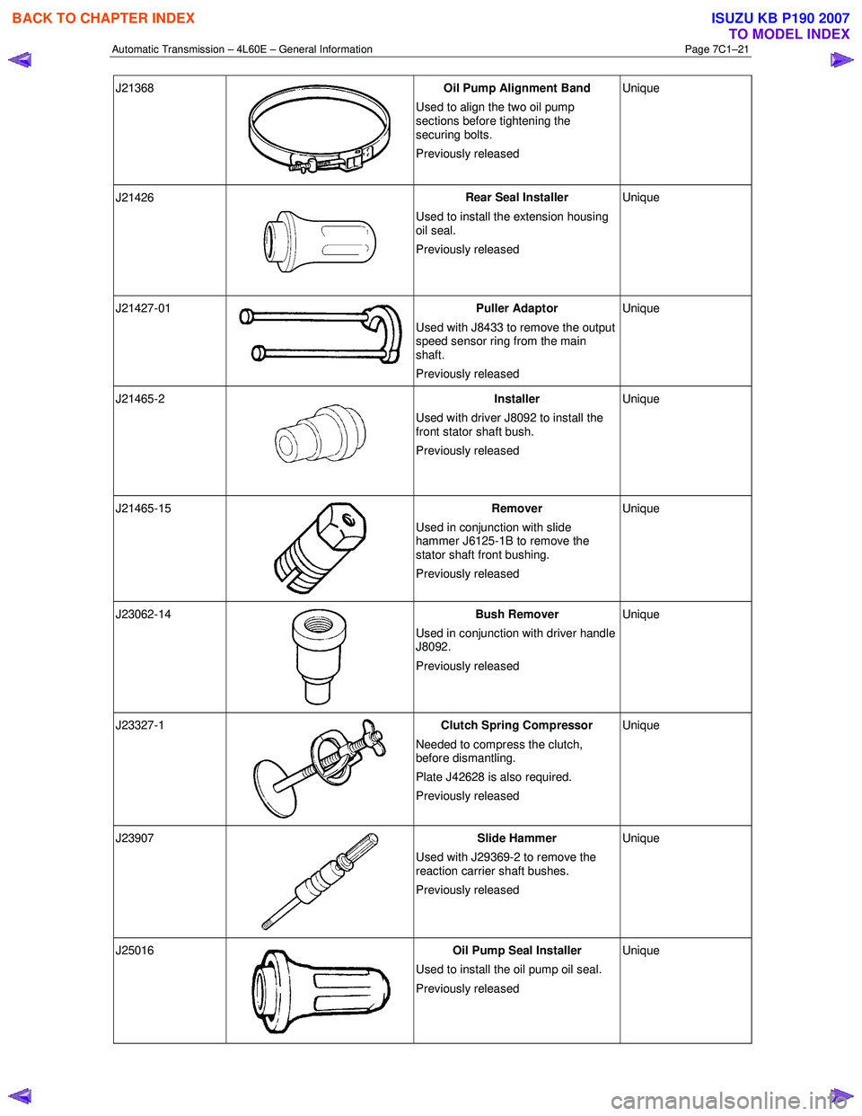
Automatic Transmission – 4L60E – General Information Page 7C1–21
J21368
Oil Pump Alignment Band
Used to align the two oil pump
sections before tightening the
securing bolts.
Previously released Unique
J21426
Rear Seal Installer
Used to install the extension housing
oil seal.
Previously released Unique
J21427-01 Puller Adaptor
Used with J8433 to remove the output
speed sensor ring from the main
shaft.
Previously released Unique
J21465-2
Installer
Used with driver J8092 to install the
front stator shaft bush.
Previously released Unique
J21465-15
Remover
Used in conjunction with slide
hammer J6125-1B to remove the
stator shaft front bushing.
Previously released Unique
J23062-14
Bush Remover
Used in conjunction with driver handle
J8092.
Previously released Unique
J23327-1
Clutch Spring Compressor
Needed to compress the clutch,
before dismantling.
Plate J42628 is also required.
Previously released Unique
J23907
Slide Hammer
Used with J29369-2 to remove the
reaction carrier shaft bushes.
Previously released Unique
J25016
Oil Pump Seal Installer
Used to install the oil pump oil seal.
Previously released Unique
BACK TO CHAPTER INDEX
TO MODEL INDEX
ISUZU KB P190 2007
Page 3783 of 6020
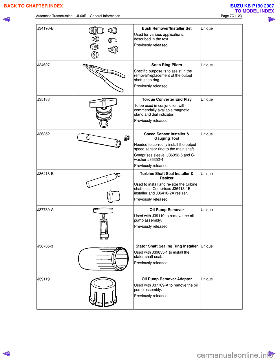
Automatic Transmission – 4L60E – General Information Page 7C1–23
J34196-B
Bush Remover/Installer Set
Used for various applications,
described in the text.
Previously released Unique
J34627
Snap Ring Pliers
Specific purpose is to assist in the
removal/replacement of the output
shaft snap ring.
Previously released Unique
J35138
Torque Converter End Play
To be used in conjunction with
commercially available magnetic
stand and dial indicator.
Previously released Unique
J36352 Speed Sensor Installer &
Gauging Tool
Needed to correctly install the output
speed sensor ring to the main shaft.
Comprises sleeve, J36352-6 and C-
washer J36352-4.
Previously released Unique
J36418-B
Turbine Shaft Seal Installer &
Resizer
Used to install and re-size the turbine
shaft seal. Comprises J36418-1B
installer and J36418-2A resizer.
Previously released Unique
J37789-A
Oil Pump Remover
Used with J39119 to remove the oil
pump assembly.
Previously released Unique
J38735-3 Stator Shaft Sealing Ring Installer
Used with J39855-1 to install the
stator shaft seal.
Previously released Unique
J39119
Oil Pump Remover Adaptor
Used with J37789-A to remove the oil
pump assembly.
Previously released Unique
BACK TO CHAPTER INDEX
TO MODEL INDEX
ISUZU KB P190 2007