2007 ISUZU KB P190 oil
[x] Cancel search: oilPage 3940 of 6020
Automatic Transmission – 4L60E – On-vehicle Servicing Page 7C4–27
To prevent personal injury, wear safety
glasses when removing the clip.
NOTE
Note the following when removing the solenoid:
• If required, rotate the solenoid until the flat
part of the clip becomes visible.
• The removal is only necessary to access the
TCC solenoid attaching bolts.
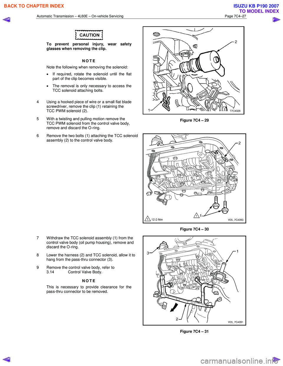
4 Using a hooked piece of wire or a small flat blade screwdriver, remove the clip (1) retaining the
TCC PWM solenoid (2).
5 With a twisting and pulling motion remove the TCC PWM solenoid from the control valve body,
remove and discard the O-ring.
Figure 7C4 – 29
6 Remove the two bolts (1) attaching the TCC solenoid assembly (2) to the control valve body.
Figure 7C4 – 30
7 W ithdraw the TCC solenoid assembly (1) from the control valve body (oil pump housing), remove and
discard the O-ring.
8 Lower the harness (2) and TCC solenoid, allow it to hang from the pass-thru connector (3).
9 Remove the control valve body, refer to 3.14 Control Valve Body.
NOTE
This is necessary to provide clearance for the
pass-thru connector to be removed.
Figure 7C4 – 31
BACK TO CHAPTER INDEX
TO MODEL INDEX
ISUZU KB P190 2007
Page 3942 of 6020
Automatic Transmission – 4L60E – On-vehicle Servicing Page 7C4–29
6 Lubricate a new O-ring with petroleum jelly and fit it to
the TCC PW M solenoid (2).
7 Reinstall the TCC PWM solenoid in the control valve body and secure it with the retaining clip (1).
Figure 7C4 – 34
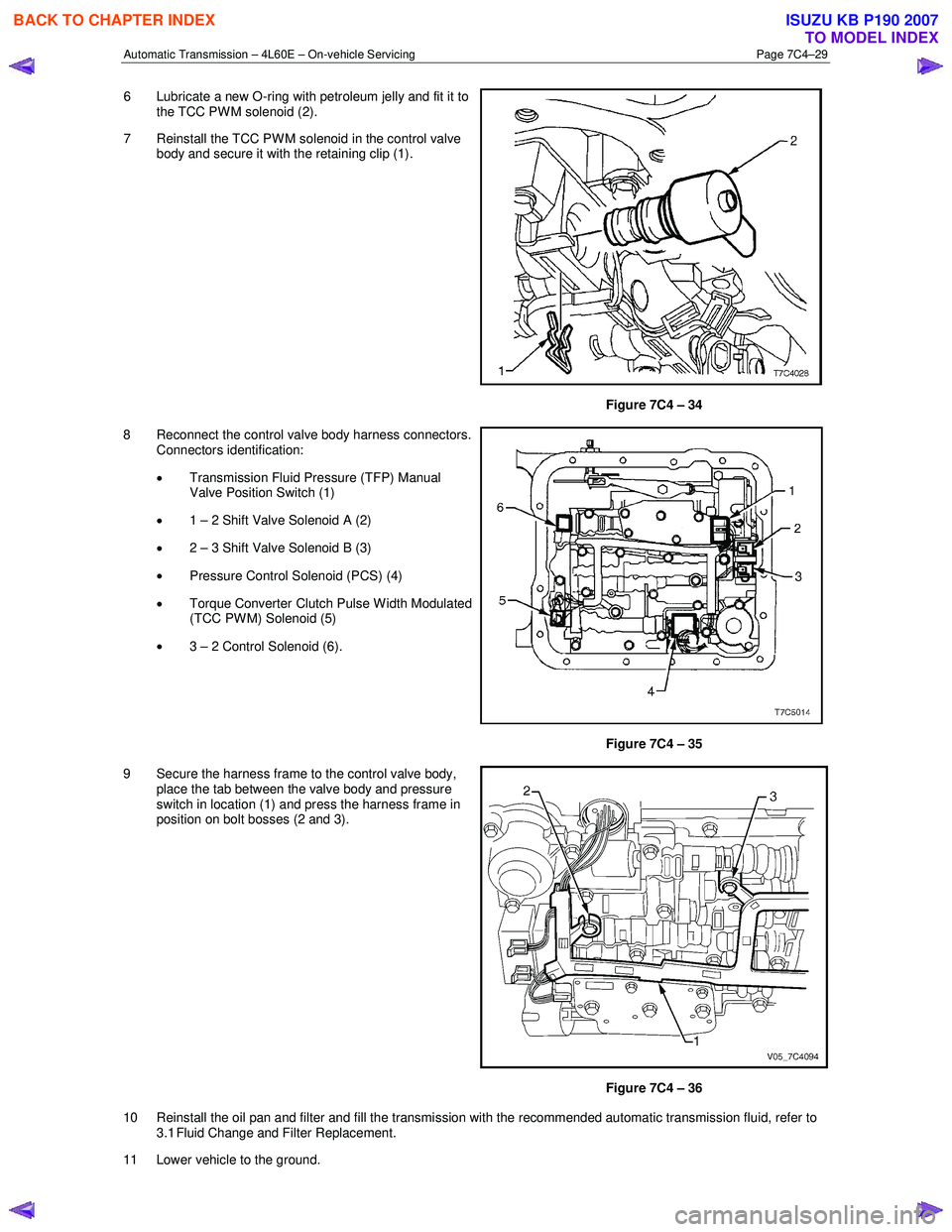
8 Reconnect the control valve body harness connectors. Connectors identification:
• Transmission Fluid Pressure (TFP) Manual
Valve Position Switch (1)
• 1 – 2 Shift Valve Solenoid A (2)
• 2 – 3 Shift Valve Solenoid B (3)
• Pressure Control Solenoid (PCS) (4)
• Torque Converter Clutch Pulse W idth Modulated
(TCC PWM) Solenoid (5)
• 3 – 2 Control Solenoid (6).
Figure 7C4 – 35
9 Secure the harness frame to the control valve body, place the tab between the valve body and pressure
switch in location (1) and press the harness frame in
position on bolt bosses (2 and 3).
Figure 7C4 – 36
10 Reinstall the oil pan and filter and fill the transmission with the recommended automatic transmission fluid, refer to 3.1 Fluid Change and Filter Replacement.
11 Lower vehicle to the ground.
BACK TO CHAPTER INDEX
TO MODEL INDEX
ISUZU KB P190 2007
Page 3943 of 6020

Automatic Transmission – 4L60E – On-vehicle Servicing Page 7C4–30
12 Road test until the transmission has reached operating temperature. Re-check the fluid level and for any fluid leaks
from the oil pan area, refer to 2.1 Transmission Fluid.
3.14 Control Valve Body
Remove
1 Partially remove the control valve body harness until it hangs from the pass-thru connector, refer to
3.13 Control Valve Body Harness.
2 Remove the three long bolts (1) and the two short bolts (2) attaching the transmission fluid pressure
(TFP) manual valve position switch assembly (3),
remove the switch and discard the shield (4).
3 Remove the attaching bolt (5) and the manual detent spring (6).
Figure 7C4 – 37
In the following procedure support the
control valve body before removing the last
bolt.
NOTE
The removal may be more manageable by
removing the bolts in a spiral pattern starting
from the outside, removing the centre bolt last.
4 Remove the fourteen remaining bolts (1) attaching the control valve body.
Figure 7C4 – 38
BACK TO CHAPTER INDEX
TO MODEL INDEX
ISUZU KB P190 2007
Page 3952 of 6020
Automatic Transmission – 4L60E – On-vehicle Servicing Page 7C4–39
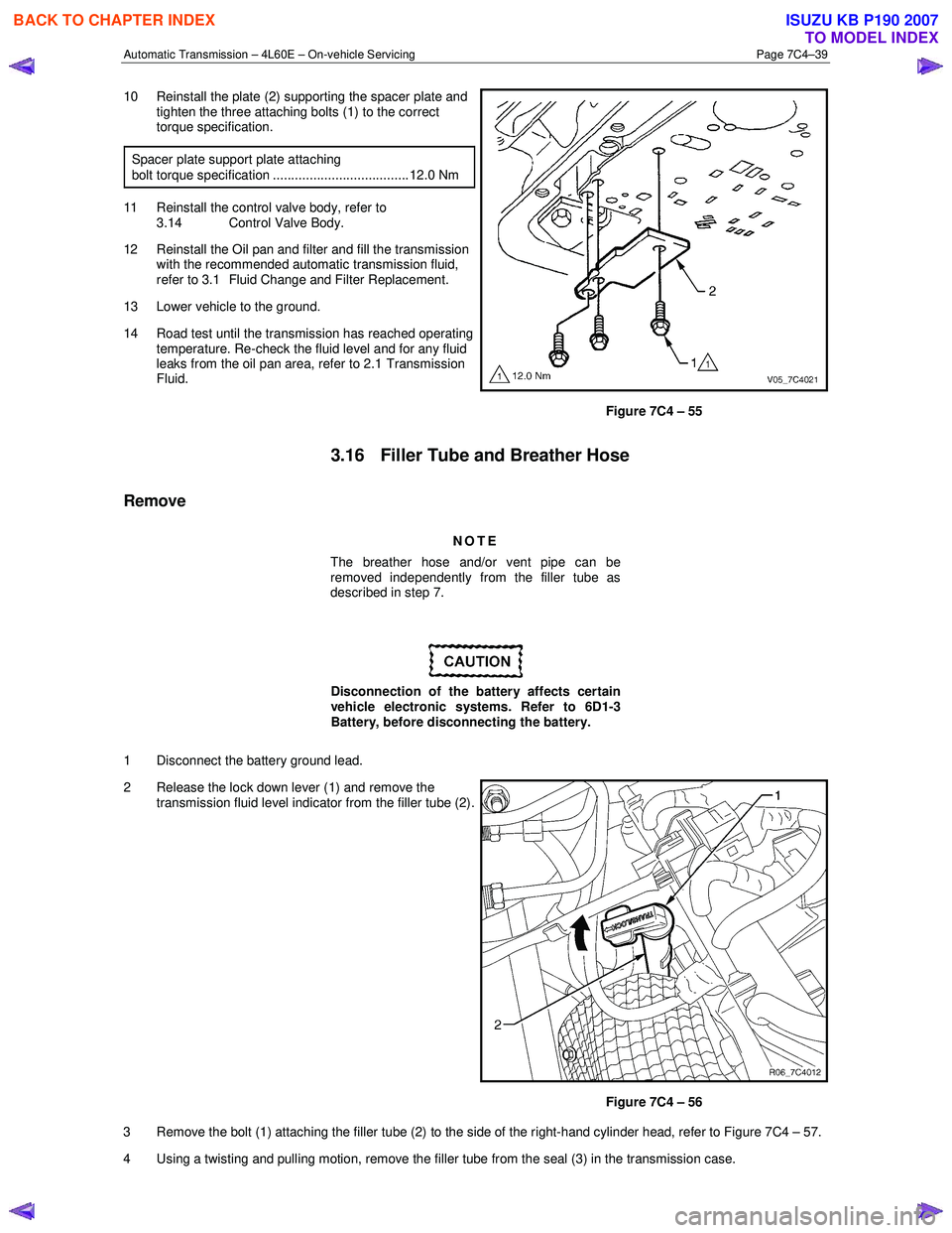
10 Reinstall the plate (2) supporting the spacer plate and
tighten the three attaching bolts (1) to the correct
torque specification.
Spacer plate support plate attaching
bolt torque specification ..................................... 12.0 Nm
11 Reinstall the control valve body, refer to 3.14 Control Valve Body.
12 Reinstall the Oil pan and filter and fill the transmission with the recommended automatic transmission fluid,
refer to 3.1 Fluid Change and Filter Replacement.
13 Lower vehicle to the ground.
14 Road test until the transmission has reached operating temperature. Re-check the fluid level and for any fluid
leaks from the oil pan area, refer to 2.1 Transmission
Fluid.
Figure 7C4 – 55
3.16 Filler Tube and Breather Hose
Remove
NOTE
The breather hose and/or vent pipe can be
removed independently from the filler tube as
described in step 7.
Disconnection of the battery affects certain
vehicle electronic systems. Refer to 6D1-3
Battery, before disconnecting the battery.
1 Disconnect the battery ground lead.
2 Release the lock down lever (1) and remove the transmission fluid level indicator from the filler tube (2).
Figure 7C4 – 56
3 Remove the bolt (1) attaching the filler tube (2) to the side of the right-hand cylinder head, refer to Figure 7C4 – 57.
4 Using a twisting and pulling motion, remove the filler tube from the seal (3) in the transmission case.
BACK TO CHAPTER INDEX
TO MODEL INDEX
ISUZU KB P190 2007
Page 3958 of 6020
Automatic Transmission – 4L60E – On-vehicle Servicing Page 7C4–45
Support the transmission when removing the
attaching bolts to avoid damage to the torque
converter and flexplate. Do not have the
transmission hanging.
NOTE
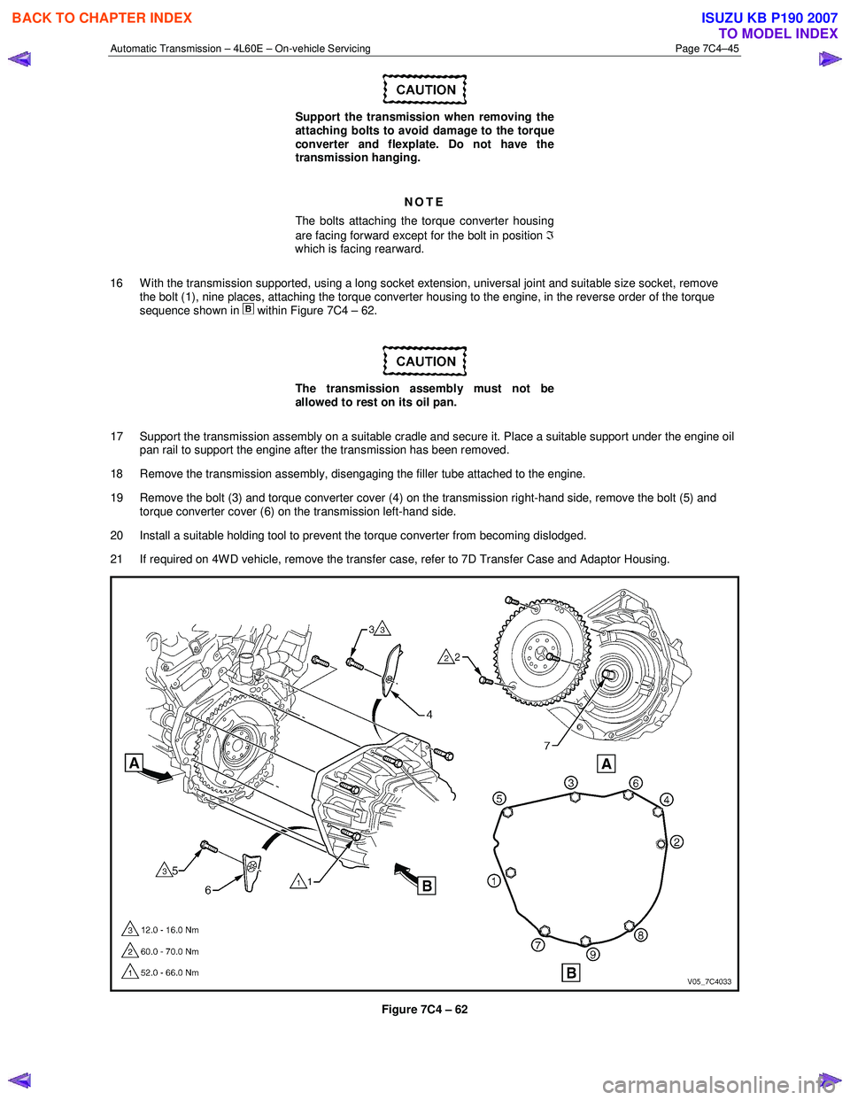
The bolts attaching the torque converter housing
are facing forward except for the bolt in position ℑ
which is facing rearward.
16 W ith the transmission supported, using a long socket extension, universal joint and suitable size socket, remove the bolt (1), nine places, attaching the torque converter housing to the engine, in the reverse order of the torque
sequence shown in
within Figure 7C4 – 62.
The transmission assembly must not be
allowed to rest on its oil pan.
17 Support the transmission assembly on a suitable cradle and secure it. Place a suitable support under the engine oil pan rail to support the engine after the transmission has been removed.
18 Remove the transmission assembly, disengaging the filler tube attached to the engine.
19 Remove the bolt (3) and torque converter cover (4) on the transmission right-hand side, remove the bolt (5) and torque converter cover (6) on the transmission left-hand side.
20 Install a suitable holding tool to prevent the torque converter from becoming dislodged.
21 If required on 4W D vehicle, remove the transfer case, refer to 7D Transfer Case and Adaptor Housing.
Figure 7C4 – 62
BACK TO CHAPTER INDEX
TO MODEL INDEX
ISUZU KB P190 2007
Page 3960 of 6020
Automatic Transmission – 4L60E – On-vehicle Servicing Page 7C4–47
14 Reconnect the fuel and EVAP pipes three brackets and clips, refer to 6C Fuel System – V6.
15 Reinstall the following components:
a Starter motor, refer to 6D1-2 Starting System.
b Transmission support, refer to 3.7 Transmission Support and Mount.
c Front and centre exhaust assemblies, refer to 6F Exhaust System.
d Rear propeller shaft and for 4WD front propeller shaft, refer to 4A Propeller Shaft.
16 Reconnect the harness connectors to the following: a Vehicle speed sensor, refer to 3.5 Vehicle Speed Sensor.
b Neutral start and back-up switch, refer to 3.4 Neutral Start and Back-up Lamp Switch.
c For the following on 4W D vehicles, refer to 7D Transfer Case and Adaptor Housing:
• neutral switch,
• 2WD – 4WD shift actuator switch,
• speed sensor.
17 Reinstall the selector cable to the transmission external manual shaft linkage, secure the selector cable to the bracket and attach the heat shield to the neutral start and back-up lamp switch, refer to 3.3 Selector Cable
Assembly.
18 Perform a reverse flush of the cooler lines and a flow rate test, refer to 2.2 Reverse Flush and Flow Rate, if either of the following applies:
• the transmission fluid is contaminated,
• the transmission has been replaced,
• the torque converter has been replaced, or
• the transmission oil pump has been replaced.
19 Lower the vehicle to the ground.
20 If required, top up the transmission fluid level (cold).
21 Reconnect the battery ground lead.
22 Start the engine and check for any fluid leaking at the fittings. If a leak is found, stop the engine and rectify the leak.
23 Road test until the transmission has reached operating temperature. Re-check the fluid level and for any fluid leaks, refer to 2.1 Transmission Fluid.
3.19 Transmission Control Module
Remove
1 Ensure the ignition switch is in the OFF position.
2 Disconnect the connector (1) from the transmission control module (TCM) (2) as follows, refer to Figure 7C4 – 63: a remove the securing pin (3),
b press the locking tab and swing the lever (4) to free the connector,
c remove the connector.
3 Remove the four bolts (5) and nuts (6), then the TCM from the mounting bracket (7).
4 If required, remove the two nuts (8) and the mounting bracket from the firewall.
BACK TO CHAPTER INDEX
TO MODEL INDEX
ISUZU KB P190 2007
Page 3974 of 6020
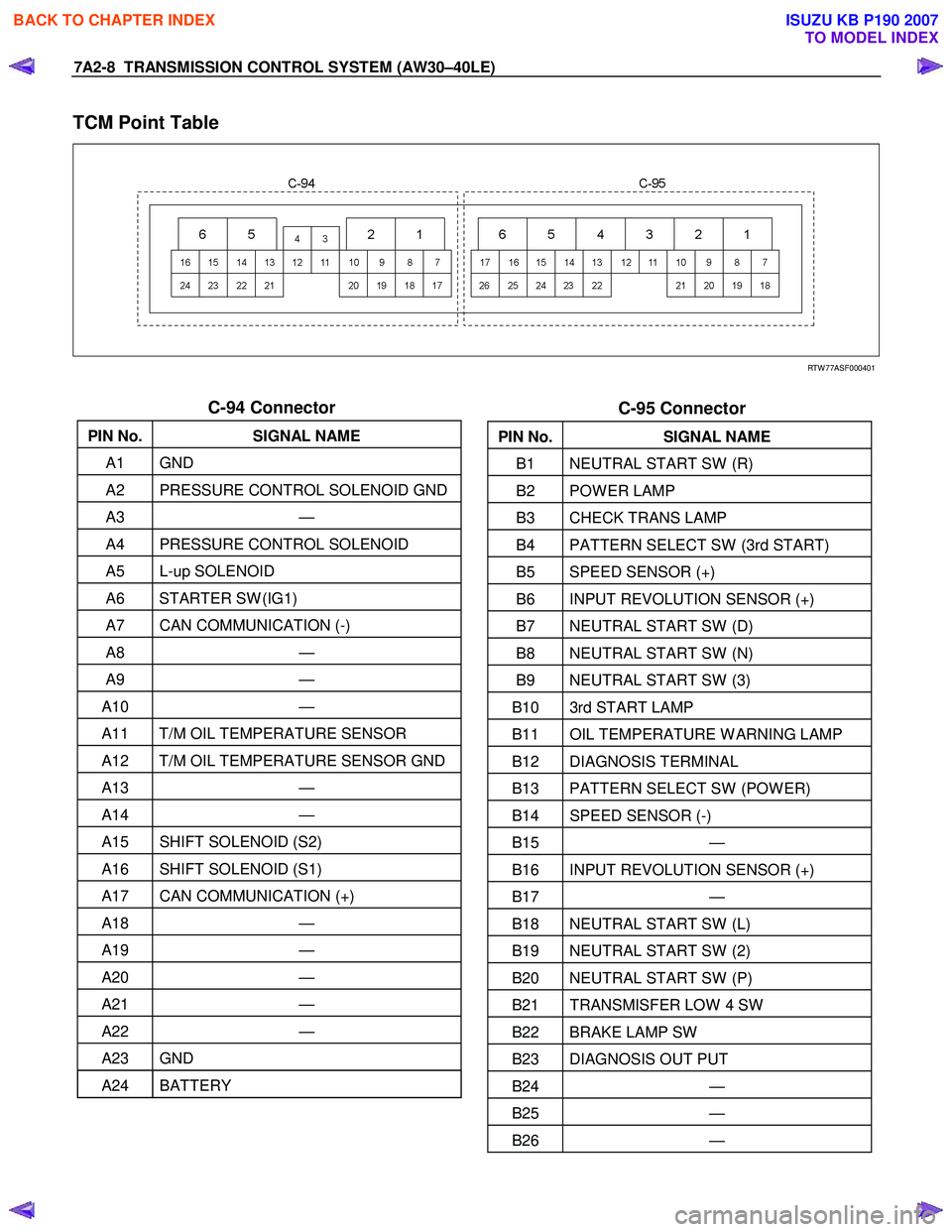
7A2-8 TRANSMISSION CONTROL SYSTEM (AW30–40LE)
TCM Point Table
RTW 77ASF000401
C-94 Connector
PIN No. SIGNAL NAME
A1 GND
A2 PRESSURE CONTROL SOLENOID GND
A3 —
A4 PRESSURE CONTROL SOLENOID
A5 L-up SOLENOID
A6 STARTER SW (IG1)
A7 CAN COMMUNICATION (-)
A8 —
A9 —
A10 —
A11 T/M OIL TEMPERATURE SENSOR
A12 T/M OIL TEMPERATURE SENSOR GND
A13 —
A14 —
A15 SHIFT SOLENOID (S2)
A16 SHIFT SOLENOID (S1)
A17 CAN COMMUNICATION (+)
A18 —
A19 —
A20 —
A21 —
A22 —
A23 GND
A24 BATTERY
C-95 Connector
PIN No. SIGNAL NAME
B1 NEUTRAL START SW (R)
B2 POW ER LAMP
B3 CHECK TRANS LAMP
B4 PATTERN SELECT SW (3rd START)
B5 SPEED SENSOR (+)
B6 INPUT REVOLUTION SENSOR (+)
B7 NEUTRAL START SW (D)
B8 NEUTRAL START SW (N)
B9 NEUTRAL START SW (3)
B10 3rd START LAMP
B11 OIL TEMPERATURE W ARNING LAMP
B12 DIAGNOSIS TERMINAL
B13 PATTERN SELECT SW (POW ER)
B14 SPEED SENSOR (-)
B15 —
B16 INPUT REVOLUTION SENSOR (+)
B17 —
B18 NEUTRAL START SW (L)
B19 NEUTRAL START SW (2)
B20 NEUTRAL START SW (P)
B21 TRANSMISFER LOW 4 SW
B22 BRAKE LAMP SW
B23 DIAGNOSIS OUT PUT
B24 —
B25 —
B26 —
BACK TO CHAPTER INDEX
TO MODEL INDEX
ISUZU KB P190 2007
Page 3975 of 6020
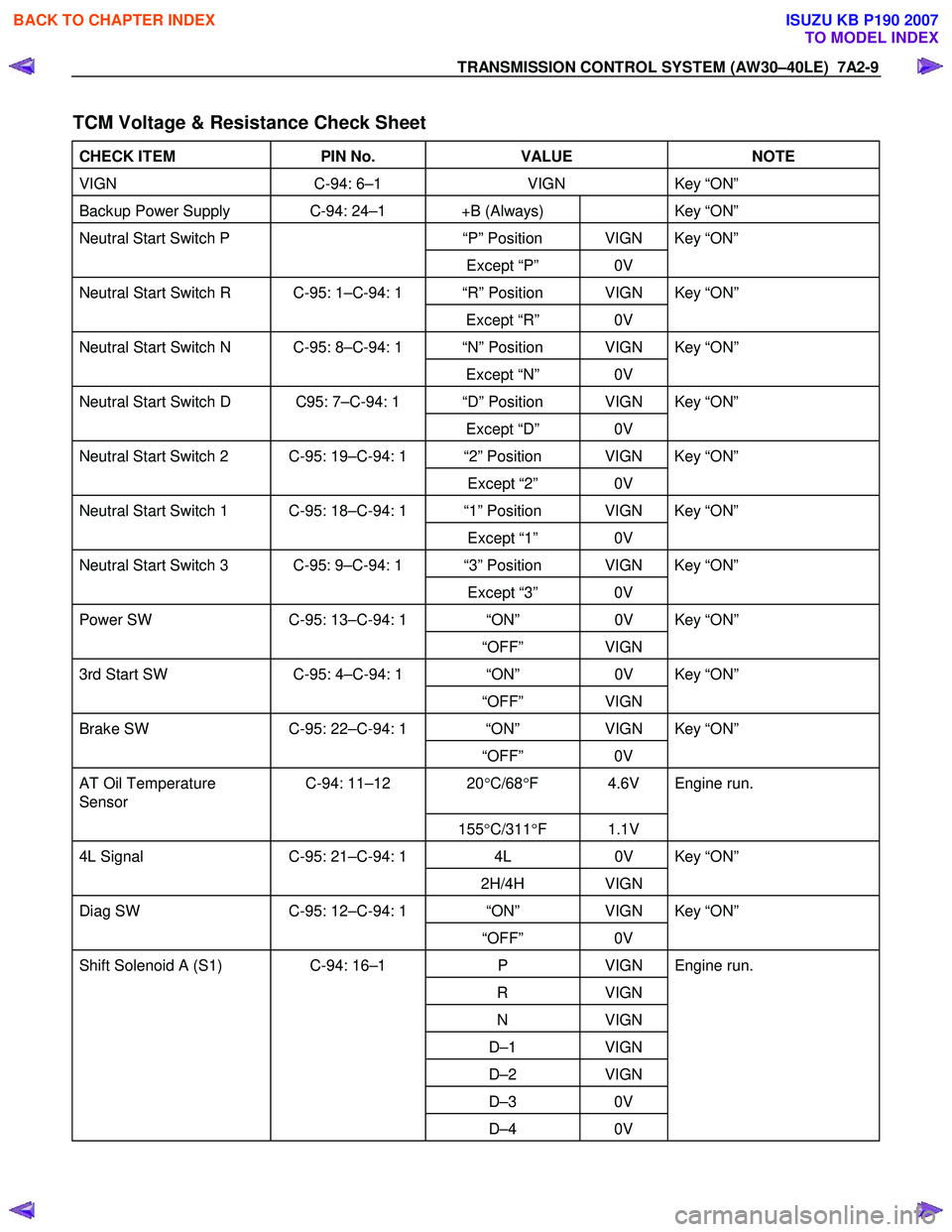
TRANSMISSION CONTROL SYSTEM (AW30–40LE) 7A2-9
TCM Voltage & Resistance Check Sheet
CHECK ITEM PIN No. VALUE NOTE
VIGN C-94: 6–1 VIGN Key “ON”
Backup Power Supply C-94: 24–1 +B (Always) Key “ON”
Neutral Start Switch P “P” Position VIGN Key “ON”
Except “P” 0V
Neutral Start Switch R C-95: 1–C-94: 1 “R” Position VIGN Key “ON”
Except “R” 0V
Neutral Start Switch N C-95: 8–C-94: 1 “N” Position VIGN Key “ON”
Except “N” 0V
Neutral Start Switch D C95: 7–C-94: 1 “D” Position VIGN Key “ON”
Except “D” 0V
Neutral Start Switch 2 C-95: 19–C-94: 1 “2” Position VIGN Key “ON”
Except “2” 0V
Neutral Start Switch 1 C-95: 18–C-94: 1 “1” Position VIGN Key “ON”
Except “1” 0V
Neutral Start Switch 3 C-95: 9–C-94: 1 “3” Position VIGN Key “ON”
Except “3” 0V
Power SW C-95: 13–C-94: 1 “ON” 0V Key “ON”
“OFF” VIGN
3rd Start SW C-95: 4–C-94: 1 “ON” 0V Key “ON”
“OFF” VIGN
Brake SW C-95: 22–C-94: 1 “ON” VIGN Key “ON”
“OFF” 0V
AT Oil Temperature
Sensor C-94: 11–12 20
°C/68 °F 4.6V Engine run.
155°C/311 °F 1.1V
4L Signal C-95: 21–C-94: 1 4L 0V Key “ON”
2H/4H VIGN
Diag SW C-95: 12–C-94: 1 “ON” VIGN Key “ON”
“OFF” 0V
Shift Solenoid A (S1) C-94: 16–1 P VIGN Engine run.
R VIGN
N VIGN
D–1 VIGN
D–2 VIGN
D–3 0V
D–4 0V
BACK TO CHAPTER INDEX
TO MODEL INDEX
ISUZU KB P190 2007