2007 INFINITI QX56 ESP
[x] Cancel search: ESPPage 1333 of 3061
EC-250
< SERVICE INFORMATION >
DTC P0133, P0153 A/F SENSOR 1
DTC P0133, P0153 A/F SENSOR 1
Component DescriptionINFOID:0000000003531758
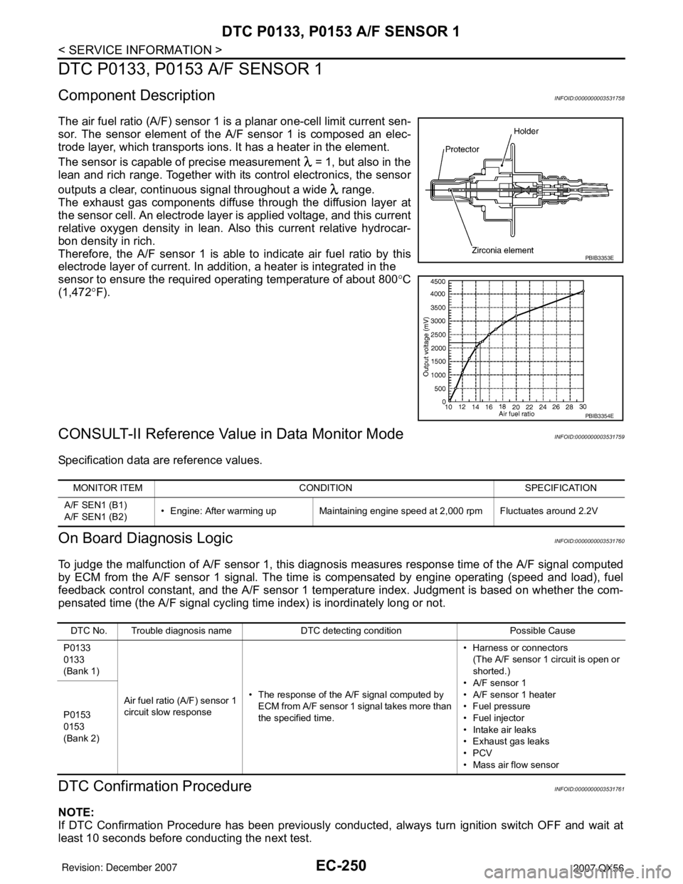
The air fuel ratio (A/F) sensor 1 is a planar one-cell limit current sen-
sor. The sensor element of the A/F sensor 1 is composed an elec-
trode layer, which transports ions. It has a heater in the element.
The sensor is capable of precise measurement = 1, but also in the
lean and rich range. Together with its control electronics, the sensor
outputs a clear, continuous signal throughout a wide range.
The exhaust gas components diffuse through the diffusion layer at
the sensor cell. An electrode layer is applied voltage, and this current
relative oxygen density in lean. Also this current relative hydrocar-
bon density in rich.
Therefore, the A/F sensor 1 is able to indicate air fuel ratio by this
electrode layer of current. In addition, a heater is integrated in the
sensor to ensure the required operating temperature of about 800°C
(1,472°F).
CONSULT-II Reference Value in Data Monitor ModeINFOID:0000000003531759
Specification data are reference values.
On Board Diagnosis LogicINFOID:0000000003531760
To judge the malfunction of A/F sensor 1, this diagnosis measures response time of the A/F signal computed
by ECM from the A/F sensor 1 signal. The time is compensated by engine operating (speed and load), fuel
feedback control constant, and the A/F sensor 1 temperature index. Judgment is based on whether the com-
pensated time (the A/F signal cycling time index) is inordinately long or not.
DTC Confirmation ProcedureINFOID:0000000003531761
NOTE:
If DTC Confirmation Procedure has been previously conducted, always turn ignition switch OFF and wait at
least 10 seconds before conducting the next test.
PBIB3353E
PBIB3354E
MONITOR ITEM CONDITION SPECIFICATION
A/F SEN1 (B1)
A/F SEN1 (B2)• Engine: After warming up Maintaining engine speed at 2,000 rpm Fluctuates around 2.2V
DTC No. Trouble diagnosis name DTC detecting condition Possible Cause
P0133
0133
(Bank 1)
Air fuel ratio (A/F) sensor 1
circuit slow response• The response of the A/F signal computed by
ECM from A/F sensor 1 signal takes more than
the specified time.• Harness or connectors
(The A/F sensor 1 circuit is open or
shorted.)
• A/F sensor 1
• A/F sensor 1 heater
• Fuel pressure
• Fuel injector
• Intake air leaks
• Exhaust gas leaks
•PCV
• Mass air flow sensor P0153
0153
(Bank 2)
Page 1365 of 3061
EC-282
< SERVICE INFORMATION >
DTC P0139, P0159 HO2S2
DTC P0139, P0159 HO2S2
Component DescriptionINFOID:0000000003531783
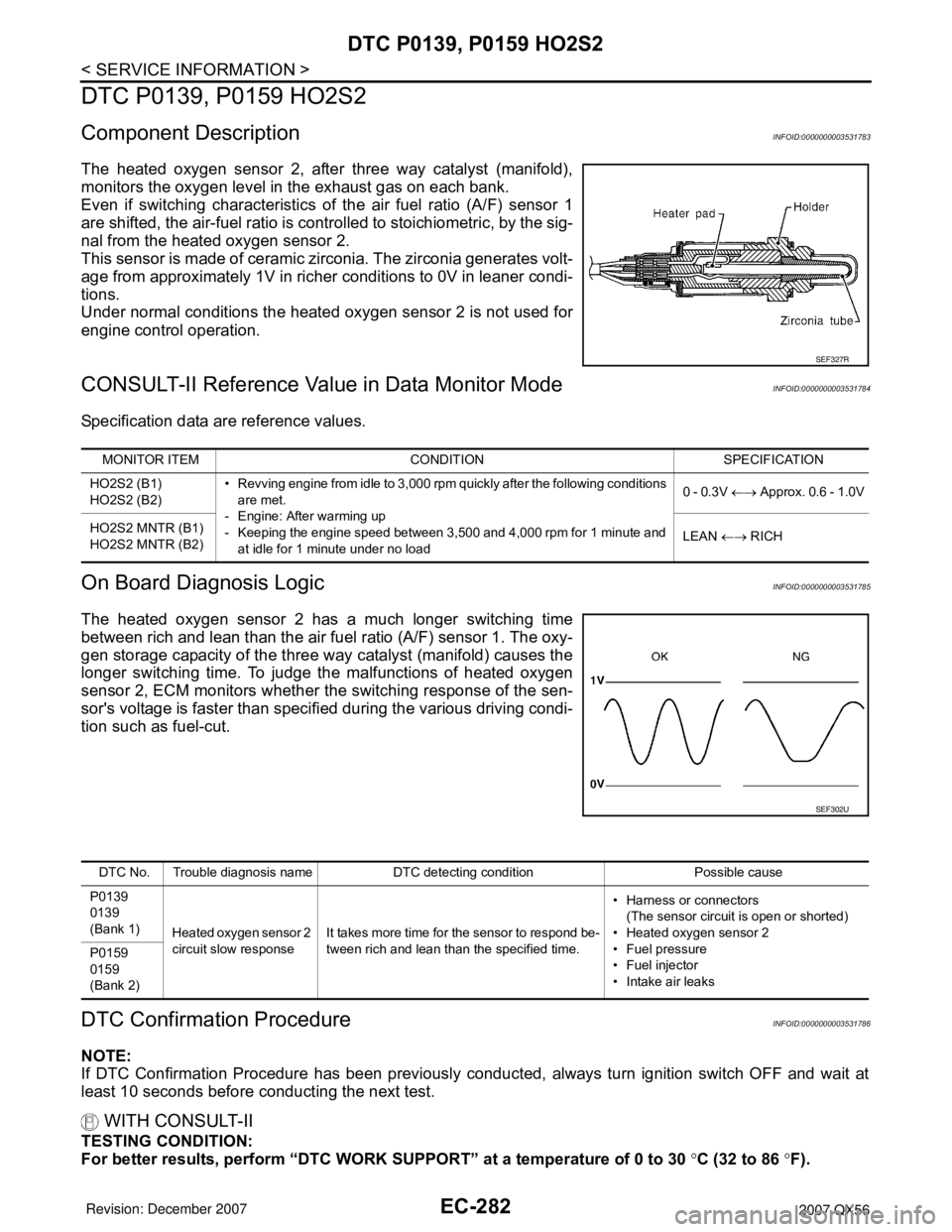
The heated oxygen sensor 2, after three way catalyst (manifold),
monitors the oxygen level in the exhaust gas on each bank.
Even if switching characteristics of the air fuel ratio (A/F) sensor 1
are shifted, the air-fuel ratio is controlled to stoichiometric, by the sig-
nal from the heated oxygen sensor 2.
This sensor is made of ceramic zirconia. The zirconia generates volt-
age from approximately 1V in richer conditions to 0V in leaner condi-
tions.
Under normal conditions the heated oxygen sensor 2 is not used for
engine control operation.
CONSULT-II Reference Value in Data Monitor ModeINFOID:0000000003531784
Specification data are reference values.
On Board Diagnosis LogicINFOID:0000000003531785
The heated oxygen sensor 2 has a much longer switching time
between rich and lean than the air fuel ratio (A/F) sensor 1. The oxy-
gen storage capacity of the three way catalyst (manifold) causes the
longer switching time. To judge the malfunctions of heated oxygen
sensor 2, ECM monitors whether the switching response of the sen-
sor's voltage is faster than specified during the various driving condi-
tion such as fuel-cut.
DTC Confirmation ProcedureINFOID:0000000003531786
NOTE:
If DTC Confirmation Procedure has been previously conducted, always turn ignition switch OFF and wait at
least 10 seconds before conducting the next test.
WITH CONSULT-II
TESTING CONDITION:
For better results, perform “DTC WORK SUPPORT” at a temperature of 0 to 30 °C (32 to 86 °F).
SEF327R
MONITOR ITEM CONDITION SPECIFICATION
HO2S2 (B1)
HO2S2 (B2)• Revving engine from idle to 3,000 rpm quickly after the following conditions
are met.
- Engine: After warming up
- Keeping the engine speed between 3,500 and 4,000 rpm for 1 minute and
at idle for 1 minute under no load0 - 0.3V ←→ Approx. 0.6 - 1.0V
HO2S2 MNTR (B1)
HO2S2 MNTR (B2)LEAN ←→ RICH
SEF302U
DTC No. Trouble diagnosis name DTC detecting condition Possible cause
P0139
0139
(Bank 1)
Heated oxygen sensor 2
circuit slow responseIt takes more time for the sensor to respond be-
tween rich and lean than the specified time.• Harness or connectors
(The sensor circuit is open or shorted)
• Heated oxygen sensor 2
• Fuel pressure
• Fuel injector
• Intake air leaks P0159
0159
(Bank 2)
Page 1381 of 3061
EC-298
< SERVICE INFORMATION >
DTC P0171, P0174 FUEL INJECTION SYSTEM FUNCTION
2. Check PCV hose connection.
OK or NG
OK >> GO TO 3.
NG >> Repair or replace.
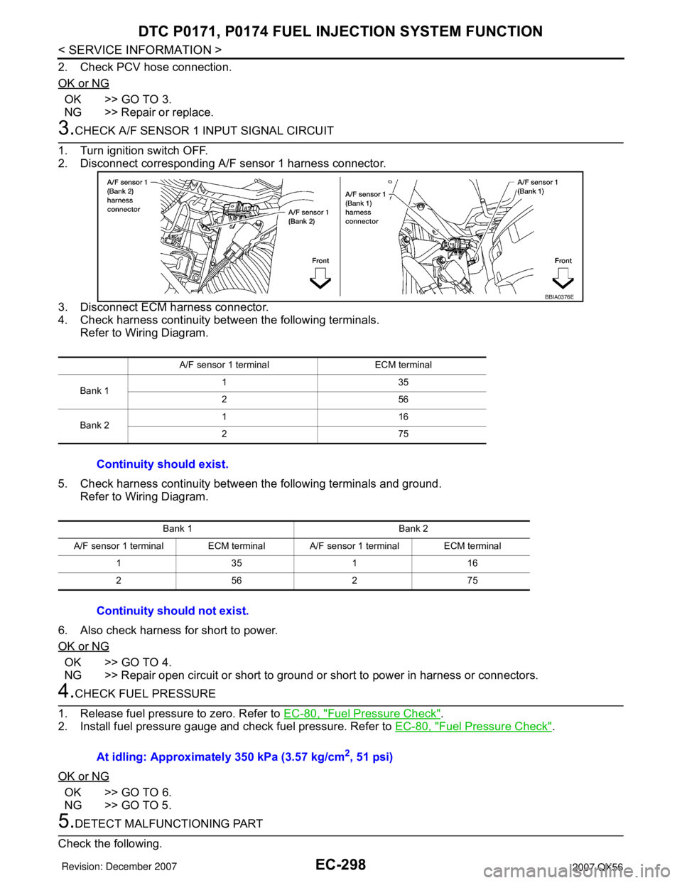
3.CHECK A/F SENSOR 1 INPUT SIGNAL CIRCUIT
1. Turn ignition switch OFF.
2. Disconnect corresponding A/F sensor 1 harness connector.
3. Disconnect ECM harness connector.
4. Check harness continuity between the following terminals.
Refer to Wiring Diagram.
5. Check harness continuity between the following terminals and ground.
Refer to Wiring Diagram.
6. Also check harness for short to power.
OK or NG
OK >> GO TO 4.
NG >> Repair open circuit or short to ground or short to power in harness or connectors.
4.CHECK FUEL PRESSURE
1. Release fuel pressure to zero. Refer to EC-80, "
Fuel Pressure Check".
2. Install fuel pressure gauge and check fuel pressure. Refer to EC-80, "
Fuel Pressure Check".
OK or NG
OK >> GO TO 6.
NG >> GO TO 5.
5.DETECT MALFUNCTIONING PART
Check the following.
A/F sensor 1 terminal ECM terminal
Bank 1135
256
Bank 2116
275
Continuity should exist.
Bank 1 Bank 2
A/F sensor 1 terminal ECM terminal A/F sensor 1 terminal ECM terminal
135116
256275
Continuity should not exist.
BBIA0376E
At idling: Approximately 350 kPa (3.57 kg/cm2, 51 psi)
Page 1390 of 3061
DTC P0172, P0175 FUEL INJECTION SYSTEM FUNCTION
EC-307
< SERVICE INFORMATION >
C
D
E
F
G
H
I
J
K
L
MA
EC
N
P O
OK or NG
OK >> GO TO 3.
NG >> Repair or replace.
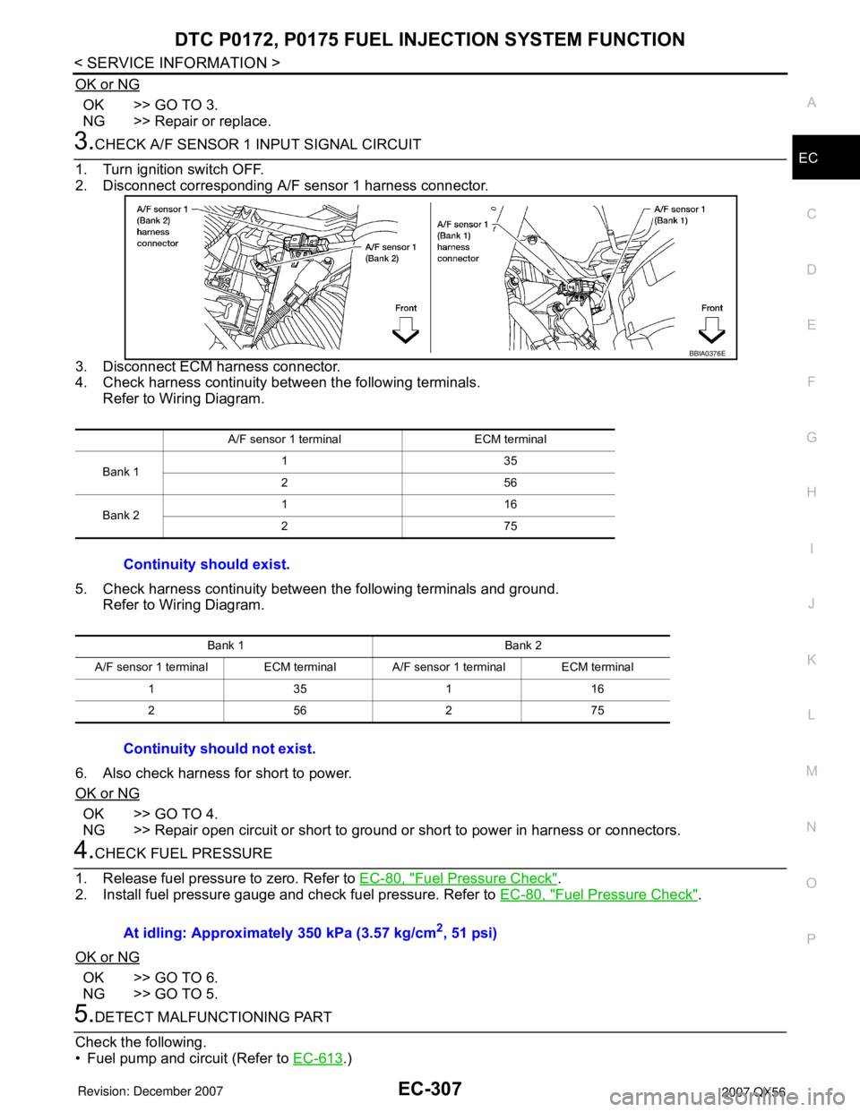
3.CHECK A/F SENSOR 1 INPUT SIGNAL CIRCUIT
1. Turn ignition switch OFF.
2. Disconnect corresponding A/F sensor 1 harness connector.
3. Disconnect ECM harness connector.
4. Check harness continuity between the following terminals.
Refer to Wiring Diagram.
5. Check harness continuity between the following terminals and ground.
Refer to Wiring Diagram.
6. Also check harness for short to power.
OK or NG
OK >> GO TO 4.
NG >> Repair open circuit or short to ground or short to power in harness or connectors.
4.CHECK FUEL PRESSURE
1. Release fuel pressure to zero. Refer to EC-80, "
Fuel Pressure Check".
2. Install fuel pressure gauge and check fuel pressure. Refer to EC-80, "
Fuel Pressure Check".
OK or NG
OK >> GO TO 6.
NG >> GO TO 5.
5.DETECT MALFUNCTIONING PART
Check the following.
• Fuel pump and circuit (Refer to EC-613
.)
A/F sensor 1 terminal ECM terminal
Bank 1135
256
Bank 2116
275
Continuity should exist.
Bank 1 Bank 2
A/F sensor 1 terminal ECM terminal A/F sensor 1 terminal ECM terminal
135116
256275
Continuity should not exist.
BBIA0376E
At idling: Approximately 350 kPa (3.57 kg/cm2, 51 psi)
Page 1401 of 3061
EC-318
< SERVICE INFORMATION >
DTC P0222, P0223 TP SENSOR
DTC P0222, P0223 TP SENSOR
Component DescriptionINFOID:0000000003531814
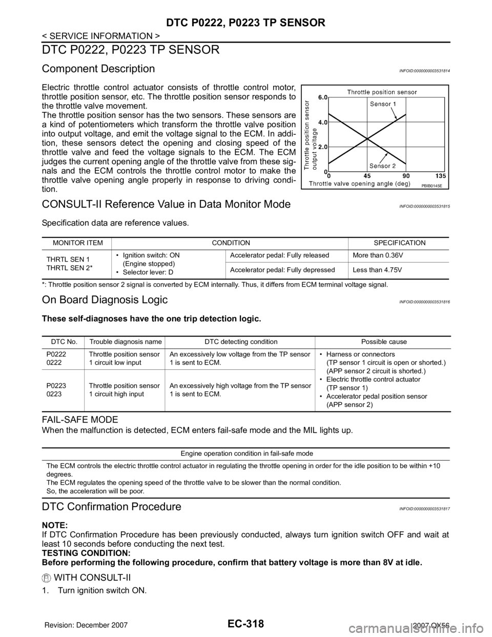
Electric throttle control actuator consists of throttle control motor,
throttle position sensor, etc. The throttle position sensor responds to
the throttle valve movement.
The throttle position sensor has the two sensors. These sensors are
a kind of potentiometers which transform the throttle valve position
into output voltage, and emit the voltage signal to the ECM. In addi-
tion, these sensors detect the opening and closing speed of the
throttle valve and feed the voltage signals to the ECM. The ECM
judges the current opening angle of the throttle valve from these sig-
nals and the ECM controls the throttle control motor to make the
throttle valve opening angle properly in response to driving condi-
tion.
CONSULT-II Reference Value in Data Monitor ModeINFOID:0000000003531815
Specification data are reference values.
*: Throttle position sensor 2 signal is converted by ECM internally. Thus, it differs from ECM terminal voltage signal.
On Board Diagnosis LogicINFOID:0000000003531816
These self-diagnoses have the one trip detection logic.
FA I L - S A F E M O D E
When the malfunction is detected, ECM enters fail-safe mode and the MIL lights up.
DTC Confirmation ProcedureINFOID:0000000003531817
NOTE:
If DTC Confirmation Procedure has been previously conducted, always turn ignition switch OFF and wait at
least 10 seconds before conducting the next test.
TESTING CONDITION:
Before performing the following procedure, confirm that battery voltage is more than 8V at idle.
WITH CONSULT-II
1. Turn ignition switch ON.
PBIB0145E
MONITOR ITEM CONDITION SPECIFICATION
THRTL SEN 1
THRTL SEN 2*• Ignition switch: ON
(Engine stopped)
• Selector lever: DAccelerator pedal: Fully released More than 0.36V
Accelerator pedal: Fully depressed Less than 4.75V
DTC No. Trouble diagnosis name DTC detecting condition Possible cause
P0222
0222Throttle position sensor
1 circuit low inputAn excessively low voltage from the TP sensor
1 is sent to ECM.• Harness or connectors
(TP sensor 1 circuit is open or shorted.)
(APP sensor 2 circuit is shorted.)
• Electric throttle control actuator
(TP sensor 1)
• Accelerator pedal position sensor
(APP sensor 2) P0223
0223Throttle position sensor
1 circuit high inputAn excessively high voltage from the TP sensor
1 is sent to ECM.
Engine operation condition in fail-safe mode
The ECM controls the electric throttle control actuator in regulating the throttle opening in order for the idle position to be within +10
degrees.
The ECM regulates the opening speed of the throttle valve to be slower than the normal condition.
So, the acceleration will be poor.
Page 1411 of 3061
EC-328
< SERVICE INFORMATION >
DTC P0300 - P0308 MULTIPLE CYLINDER MISFIRE, NO. 1 - 8 CYLINDER MIS-
FIRE
8. Crank engine for 5 seconds or more to remove combustion gas in the cylinder.
9. Connect spark plug and harness connector to ignition coil.
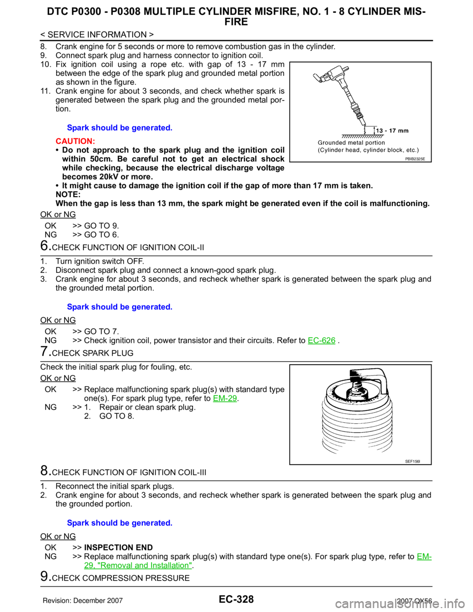
10. Fix ignition coil using a rope etc. with gap of 13 - 17 mm
between the edge of the spark plug and grounded metal portion
as shown in the figure.
11. Crank engine for about 3 seconds, and check whether spark is
generated between the spark plug and the grounded metal por-
tion.
CAUTION:
• Do not approach to the spark plug and the ignition coil
within 50cm. Be careful not to get an electrical shock
while checking, because the electrical discharge voltage
becomes 20kV or more.
• It might cause to damage the ignition coil if the gap of more than 17 mm is taken.
NOTE:
When the gap is less than 13 mm, the spark might be generated even if the coil is malfunctioning.
OK or NG
OK >> GO TO 9.
NG >> GO TO 6.
6.CHECK FUNCTION OF IGNITION COIL-II
1. Turn ignition switch OFF.
2. Disconnect spark plug and connect a known-good spark plug.
3. Crank engine for about 3 seconds, and recheck whether spark is generated between the spark plug and
the grounded metal portion.
OK or NG
OK >> GO TO 7.
NG >> Check ignition coil, power transistor and their circuits. Refer to EC-626
.
7.CHECK SPARK PLUG
Check the initial spark plug for fouling, etc.
OK or NG
OK >> Replace malfunctioning spark plug(s) with standard type
one(s). For spark plug type, refer to EM-29
.
NG >> 1. Repair or clean spark plug.
2. GO TO 8.
8.CHECK FUNCTION OF IGNITION COIL-III
1. Reconnect the initial spark plugs.
2. Crank engine for about 3 seconds, and recheck whether spark is generated between the spark plug and
the grounded portion.
OK or NG
OK >>INSPECTION END
NG >> Replace malfunctioning spark plug(s) with standard type one(s). For spark plug type, refer to EM-
29, "Removal and Installation".
9.CHECK COMPRESSION PRESSURESpark should be generated.
PBIB2325E
Spark should be generated.
SEF156I
Spark should be generated.
Page 1462 of 3061
DTC P0447 EVAP CANISTER VENT CONTROL VALVE
EC-379
< SERVICE INFORMATION >
C
D
E
F
G
H
I
J
K
L
MA
EC
N
P O
DTC P0447 EVAP CANISTER VENT CONTROL VALVE
Component DescriptionINFOID:0000000003531875
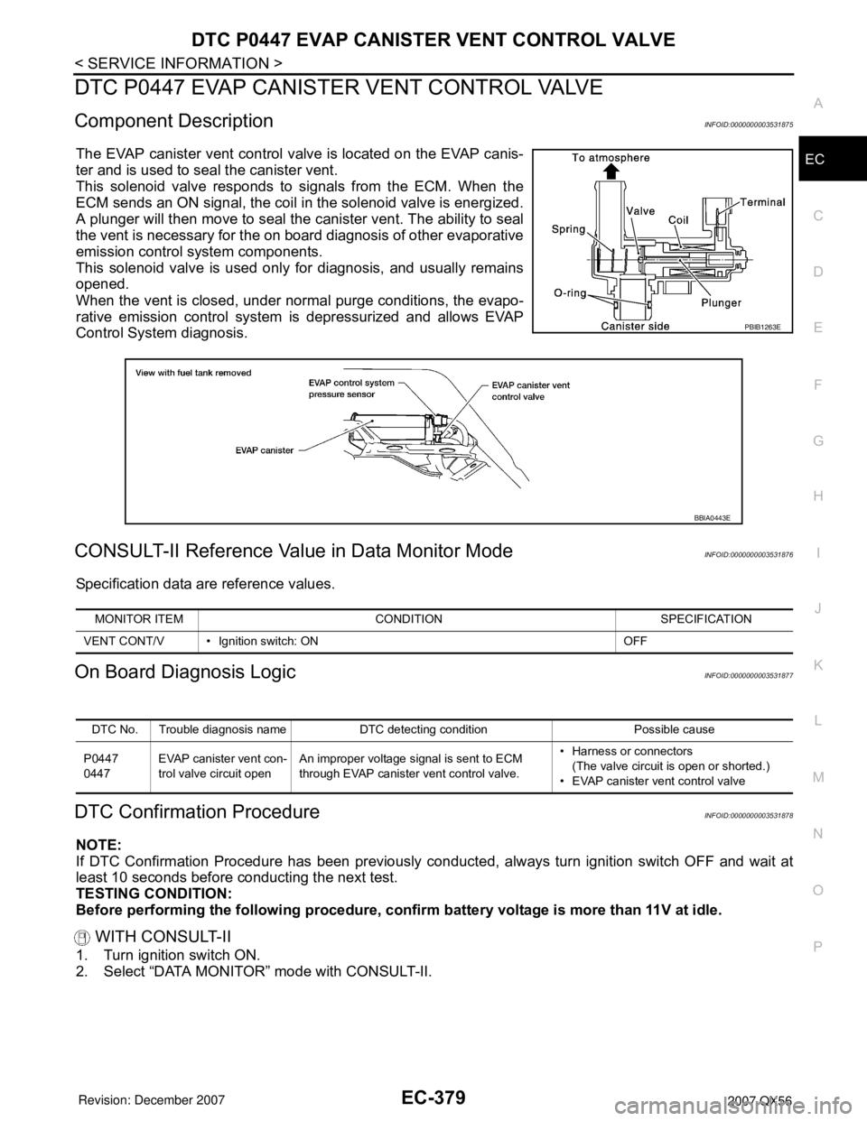
The EVAP canister vent control valve is located on the EVAP canis-
ter and is used to seal the canister vent.
This solenoid valve responds to signals from the ECM. When the
ECM sends an ON signal, the coil in the solenoid valve is energized.
A plunger will then move to seal the canister vent. The ability to seal
the vent is necessary for the on board diagnosis of other evaporative
emission control system components.
This solenoid valve is used only for diagnosis, and usually remains
opened.
When the vent is closed, under normal purge conditions, the evapo-
rative emission control system is depressurized and allows EVAP
Control System diagnosis.
CONSULT-II Reference Value in Data Monitor ModeINFOID:0000000003531876
Specification data are reference values.
On Board Diagnosis LogicINFOID:0000000003531877
DTC Confirmation ProcedureINFOID:0000000003531878
NOTE:
If DTC Confirmation Procedure has been previously conducted, always turn ignition switch OFF and wait at
least 10 seconds before conducting the next test.
TESTING CONDITION:
Before performing the following procedure, confirm battery voltage is more than 11V at idle.
WITH CONSULT-II
1. Turn ignition switch ON.
2. Select “DATA MONITOR” mode with CONSULT-II.
PBIB1263E
BBIA0443E
MONITOR ITEM CONDITION SPECIFICATION
VENT CONT/V • Ignition switch: ON OFF
DTC No. Trouble diagnosis name DTC detecting condition Possible cause
P0447
0447EVAP canister vent con-
trol valve circuit openAn improper voltage signal is sent to ECM
through EVAP canister vent control valve.• Harness or connectors
(The valve circuit is open or shorted.)
• EVAP canister vent control valve
Page 1469 of 3061
EC-386
< SERVICE INFORMATION >
DTC P0448 EVAP CANISTER VENT CONTROL VALVE
DTC P0448 EVAP CANISTER VENT CONTROL VALVE
Component DescriptionINFOID:0000000003531882
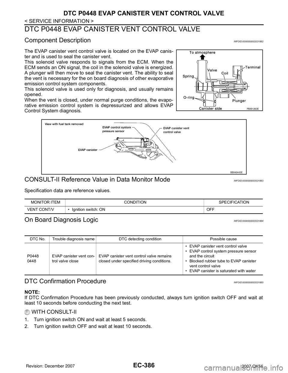
The EVAP canister vent control valve is located on the EVAP canis-
ter and is used to seal the canister vent.
This solenoid valve responds to signals from the ECM. When the
ECM sends an ON signal, the coil in the solenoid valve is energized.
A plunger will then move to seal the canister vent. The ability to seal
the vent is necessary for the on board diagnosis of other evaporative
emission control system components.
This solenoid valve is used only for diagnosis, and usually remains
opened.
When the vent is closed, under normal purge conditions, the evapo-
rative emission control system is depressurized and allows EVAP
Control System diagnosis.
CONSULT-II Reference Value in Data Monitor ModeINFOID:0000000003531883
Specification data are reference values.
On Board Diagnosis LogicINFOID:0000000003531884
DTC Confirmation ProcedureINFOID:0000000003531885
NOTE:
If DTC Confirmation Procedure has been previously conducted, always turn ignition switch OFF and wait at
least 10 seconds before conducting the next test.
WITH CONSULT-II
1. Turn ignition switch ON and wait at least 5 seconds.
2. Turn ignition switch OFF and wait at least 10 seconds.
PBIB1263E
BBIA0443E
MONITOR ITEM CONDITION SPECIFICATION
VENT CONT/V • Ignition switch: ON OFF
DTC No. Trouble diagnosis name DTC detecting condition Possible cause
P0448
0448EVAP canister vent con-
trol valve closeEVAP canister vent control valve remains
closed under specified driving conditions.• EVAP canister vent control valve
• EVAP control system pressure sensor
and the circuit
• Blocked rubber tube to EVAP canister
vent control valve
• EVAP canister is saturated with water