2007 INFINITI QX56 ESP
[x] Cancel search: ESPPage 1657 of 3061
EC-574
< SERVICE INFORMATION >
DTC P2135 TP SENSOR
DTC P2135 TP SENSOR
Component DescriptionINFOID:0000000003532125
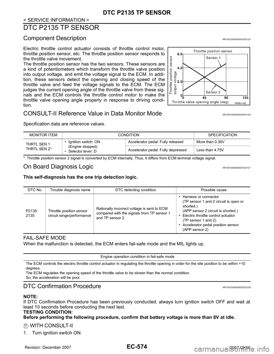
Electric throttle control actuator consists of throttle control motor,
throttle position sensor, etc. The throttle position sensor responds to
the throttle valve movement.
The throttle position sensor has the two sensors. These sensors are
a kind of potentiometers which transform the throttle valve position
into output voltage, and emit the voltage signal to the ECM. In addi-
tion, these sensors detect the opening and closing speed of the
throttle valve and feed the voltage signals to the ECM. The ECM
judges the current opening angle of the throttle valve from these sig-
nals and the ECM controls the throttle control motor to make the
throttle valve opening angle properly in response to driving condi-
tion.
CONSULT-II Reference Value in Data Monitor ModeINFOID:0000000003532126
Specification data are reference values.
*: Throttle position sensor 2 signal is converted by ECM internally. Thus, it differs from ECM terminal voltage signal.
On Board Diagnosis LogicINFOID:0000000003532127
This self-diagnosis has the one trip detection logic.
FA I L - S A F E M O D E
When the malfunction is detected, the ECM enters fail-safe mode and the MIL lights up.
DTC Confirmation ProcedureINFOID:0000000003532128
NOTE:
If DTC Confirmation Procedure has been previously conducted, always turn ignition switch OFF and wait at
least 10 seconds before conducting the next test.
TESTING CONDITION:
Before performing the following procedure, confirm that battery voltage is more than 8V at idle.
WITH CONSULT-II
1. Turn ignition switch ON.
PBIB0145E
MONITOR ITEM CONDITION SPECIFICATION
THRTL SEN 1
THRTL SEN 2*• Ignition switch: ON
(Engine stopped)
• Selector lever: DAccelerator pedal: Fully released More than 0.36V
Accelerator pedal: Fully depressed Less than 4.75V
DTC No. Trouble diagnosis name DTC detecting condition Possible cause
P2135
2135Throttle position sensor
circuit range/performanceRationally incorrect voltage is sent to ECM
compared with the signals from TP sensor 1
and TP sensor 2.• Harness or connector
(TP sensor 1 and 2 circuit is open or
shorted.)
(APP sensor 2 circuit is shorted.)
• Electric throttle control actuator
(TP sensor 1 and 2)
• Accelerator pedal position sensor
(APP sensor 2)
Engine operation condition in fail-safe mode
The ECM controls the electric throttle control actuator in regulating the throttle opening in order for the idle position to be within +10
degrees.
The ECM regulates the opening speed of the throttle valve to be slower than the normal condition.
So, the acceleration will be poor.
Page 1733 of 3061
EI-4
< SERVICE INFORMATION >
SQUEAK AND RATTLE TROUBLE DIAGNOSIS
SQUEAK AND RATTLE TROUBLE DIAGNOSIS
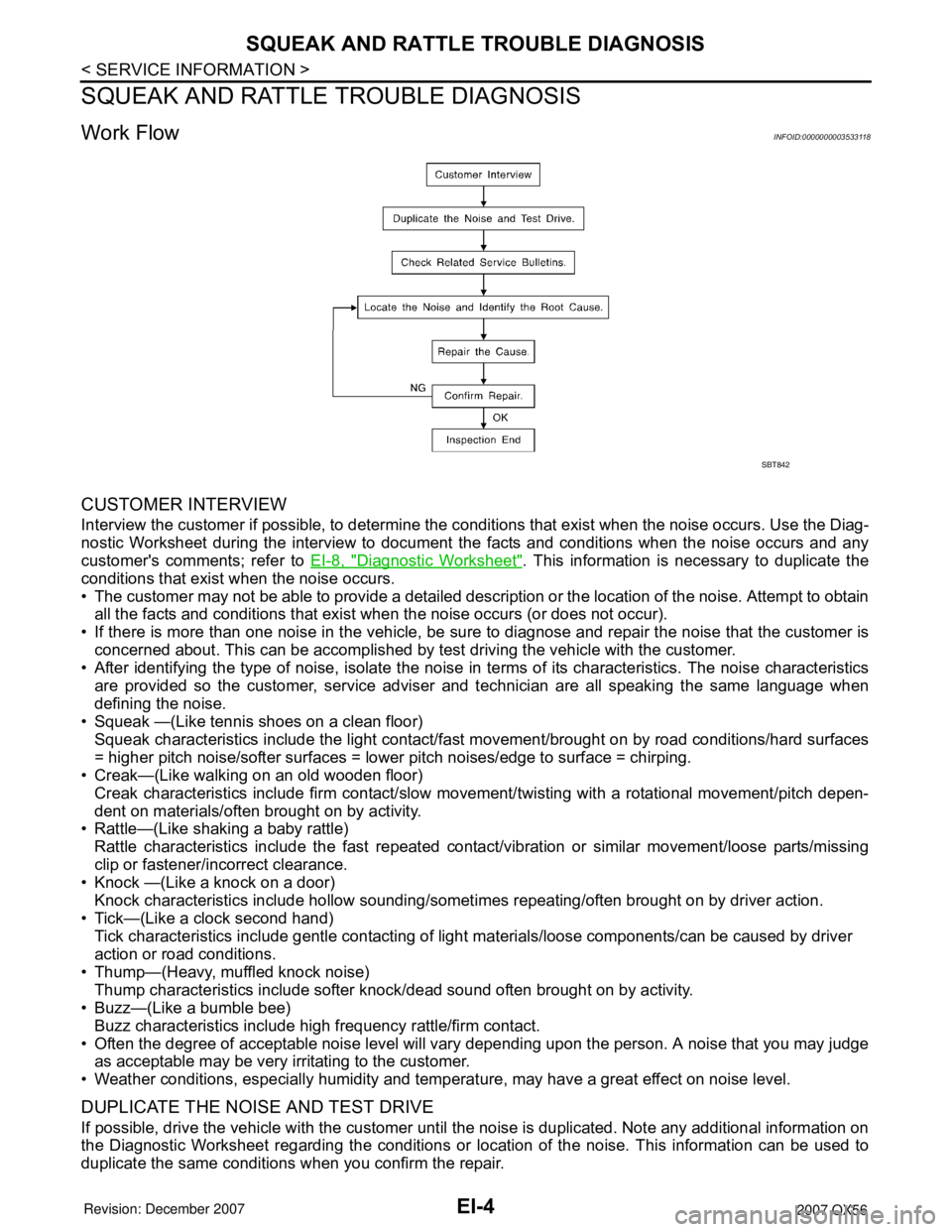
Work FlowINFOID:0000000003533118
CUSTOMER INTERVIEW
Interview the customer if possible, to determine the conditions that exist when the noise occurs. Use the Diag-
nostic Worksheet during the interview to document the facts and conditions when the noise occurs and any
customer's comments; refer to EI-8, "
Diagnostic Worksheet". This information is necessary to duplicate the
conditions that exist when the noise occurs.
• The customer may not be able to provide a detailed description or the location of the noise. Attempt to obtain
all the facts and conditions that exist when the noise occurs (or does not occur).
• If there is more than one noise in the vehicle, be sure to diagnose and repair the noise that the customer is
concerned about. This can be accomplished by test driving the vehicle with the customer.
• After identifying the type of noise, isolate the noise in terms of its characteristics. The noise characteristics
are provided so the customer, service adviser and technician are all speaking the same language when
defining the noise.
• Squeak —(Like tennis shoes on a clean floor)
Squeak characteristics include the light contact/fast movement/brought on by road conditions/hard surfaces
= higher pitch noise/softer surfaces = lower pitch noises/edge to surface = chirping.
• Creak—(Like walking on an old wooden floor)
Creak characteristics include firm contact/slow movement/twisting with a rotational movement/pitch depen-
dent on materials/often brought on by activity.
• Rattle—(Like shaking a baby rattle)
Rattle characteristics include the fast repeated contact/vibration or similar movement/loose parts/missing
clip or fastener/incorrect clearance.
• Knock —(Like a knock on a door)
Knock characteristics include hollow sounding/sometimes repeating/often brought on by driver action.
• Tick—(Like a clock second hand)
Tick characteristics include gentle contacting of light materials/loose components/can be caused by driver
action or road conditions.
• Thump—(Heavy, muffled knock noise)
Thump characteristics include softer knock/dead sound often brought on by activity.
• Buzz—(Like a bumble bee)
Buzz characteristics include high frequency rattle/firm contact.
• Often the degree of acceptable noise level will vary depending upon the person. A noise that you may judge
as acceptable may be very irritating to the customer.
• Weather conditions, especially humidity and temperature, may have a great effect on noise level.
DUPLICATE THE NOISE AND TEST DRIVE
If possible, drive the vehicle with the customer until the noise is duplicated. Note any additional information on
the Diagnostic Worksheet regarding the conditions or location of the noise. This information can be used to
duplicate the same conditions when you confirm the repair.
SBT842
Page 1759 of 3061

EI-30
< SERVICE INFORMATION >
SIDE GUARD MOLDING
2. Heat the panel and double-faced adhesive tape surface to 30° to 40°C (86° to 104°F).
3. Remove the backing sheet from the double-faced adhesive tape surface.
• Align the plastic clips into the holes in the outer door.
• Continue aligning the plastic clips into their corresponding holes in the outer door during installation.
4. Press ends by hand and use a roller to apply 5 kg-f (11 lbs-f) to press double-faced adhesive tape surface
on side guard molding to door surface.
• Apply even pressure along double-faced adhesive tape surface on side guard molding to insure proper
wet out.
CAUTION:
To secure contact of double-faced adhesive tape, do not wash vehicle for 24 hours after installation.
Page 1811 of 3061

TIMING CHAINEM-41
< SERVICE INFORMATION >
C
DE
F
G H
I
J
K L
M A
EM
NP
O
Check for cracks and any excessive wear
at link plates. Replace
chain if necessary.
• In the same way as for the LH bank, inspect the timing chain and associated parts on the RH bank.
INSTALLATION
NOTE:
• The above figure shows the relationship between the ma ting mark on each timing chain and that of the cor-
responding sprocket, with the components installed.
• To install the timing chain and associated parts, star t with those on the RH bank. The procedure for installing
parts on the LH bank is omitted because it is t he same as that for installation on the RH bank.
PBIC0282E
AWBIA0150ZZ
1. Camshaft sprocket RH bank INT
(VTC) 2. Camshaft sprocket RH bank EXH 3. Camshaft dowel pin RH bank
4. Timing chain RH bank 5. Timing chain slack guide RH bank 6. Chain tensioner (RH)
7. Crankshaft sprocket 8. Crankshaft key 9. Timing chain tension guide LH bank
10. Timing chain LH bank 11. Camshaft dowel pin LH bank 12. Camshaft sprocket LH bank EXH
13. Camshaft sprocket LH bank INT (VTC) 14. Chain tensioner LH 15. Timing chain tension guide RH bank
16. Timing chain slack guide LH bank A. LH bank B. RH bank
C. Alignment mark (Link color: copper) D . Alignment mark (Link color: copper) E. Alignment ma rk (Identification mark)
F. Alignment mark for LH bank (Notch) G. Alignment mark for LH bank (Link color: Yellow)H. Alignment mark for RH bank (Link
color: Yellow)
J. Alignment mark (Link color: copper) K. Alignment mark (Identification mark) L. Alignment mark (Identification mark)
M Alignment mark (Link color: copper) N. A lignment mark (Identification mark)
Page 1815 of 3061
TIMING CHAINEM-45
< SERVICE INFORMATION >
C
DE
F
G H
I
J
K L
M A
EM
NP
O
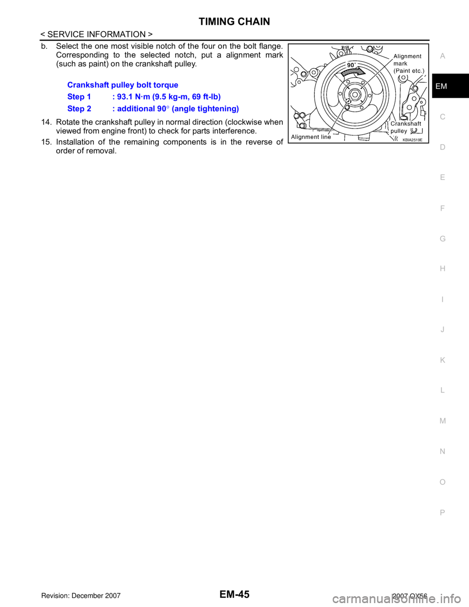
b. Select the one most visible notch of the four on the bolt flange.
Corresponding to the selected notch, put a alignment mark
(such as paint) on the crankshaft pulley.
14. Rotate the crankshaft pulley in normal direction (clockwise when viewed from engine front) to check for parts interference.
15. Installation of the remaining components is in the reverse of order of removal.Crankshaft pulley bolt torque
Step 1 : 93.1 N·m (9.5 kg-m, 69 ft-lb)
Step 2 : additional 90
° (angle tightening)
KBIA2519E
Page 1832 of 3061
EM-62
< SERVICE INFORMATION >
OIL SEAL
3. Remove the front oil seal using suitable tool.CAUTION:
Do not damage front cover and oil pump drive spacer.
INSTALLATION
1. Apply new engine oil to both the oil seal lip and dust seal lip of the new front oil seal.
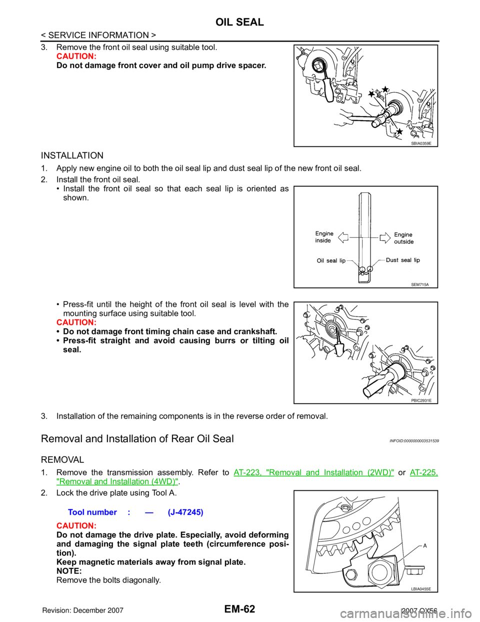
2. Install the front oil seal.• Install the front oil seal so that each seal lip is oriented as
shown.
• Press-fit until the height of the front oil seal is level with the mounting surface using suitable tool.
CAUTION:
• Do not damage front timing chain case and crankshaft.
• Press-fit straight and avoid causing burrs or tilting oil
seal.
3. Installation of the remaining components is in the reverse order of removal.
Removal and Installation of Rear Oil SealINFOID:0000000003531539
REMOVAL
1. Remove the transmission assembly. Refer to AT-223, "Removal and Installation (2WD)" or AT-225,
"Removal and Installation (4WD)".
2. Lock the drive plate using Tool A.
CAUTION:
Do not damage the drive plat e. Especially, avoid deforming
and damaging the signal plat e teeth (circumference posi-
tion).
Keep magnetic materials away from signal plate.
NOTE:
Remove the bolts diagonally.
SBIA0359E
SEM715A
PBIC2931E
Tool number : — (J-47245)
LBIA0455E
Page 1834 of 3061
EM-64
< SERVICE INFORMATION >
CYLINDER HEAD
CYLINDER HEAD
On-Vehicle ServiceINFOID:0000000003531540
CHECKING COMPRESSION PRESSURE
1. Warm up the engine thoroughly. Then stop the engine.
2. Release the fuel pressure. Refer to EC-80, "
Fuel Pressure Check".
CAUTION:
If CONSULT-II is not used to release fuel pressure leave the fu el pump fuse disconnected until
step 7.
3. Remove the spark plug from each cylinder. Refer to EM-29, "
Removal and Installation".
4. Connect the engine tachometer (not required in use of CONSULT-II).
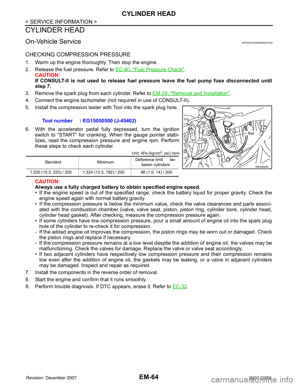
5. Install the compression tester with Tool into the spark plug hole.
6. With the accelerator pedal fully depressed, turn the ignition switch to “START” for cranking. When the gauge pointer stabi-
lizes, read the compression pressure and engine rpm. Perform
these steps to check each cylinder.
Unit: kPa (kg/cm2, psi) /rpm
CAUTION:
Always use a fully charged battery to obtain specified engine speed.
• If the engine speed is out of the specified range, che ck the battery liquid for proper gravity. Check the
engine speed again with normal battery gravity.
• If the compression pressure is below the minimum value, check the valve clearances and parts associ- ated with the combustion chamber (valve, valve seat , piston, piston ring, cylinder bore, cylinder head,
cylinder head gasket). After checking, measure the compression pressure again.
• If some cylinders have low compression pressure, pour a small amount of engine oil into the spark plug hole of the cylinder to re-check it for compression.
- If the added engine oil improves the compression, t he piston rings may be worn out or damaged. Check
the piston rings and replace if necessary.
- If the compression pressure remains at a low level despite the addition of engine oil, the valves may be
malfunctioning. Check the valves for damage. R eplace the valve or valve seat accordingly.
• If two adjacent cylinders have respectively low co mpression pressure and their compression remains
low even after the addition of engine oil, the gaskets may be leaking, or a valve in adjacent cylinders
may be damaged. Inspect and repair as required.
7. Install the components in the reverse order of removal.
8. Start the engine and confirm that it runs smoothly.
9. Perform trouble diagnosis. If DTC appears, erase it. Refer to EC-32
.
Tool number : EG15050500 (J-45402)
Standard Minimum
Deference limit be-
tween cylinders
1,520 (15.5, 220) / 200 1,324 (13.5, 192) / 200 98 (1.0, 14) / 200WBIA0605E
Page 1846 of 3061
EM-76
< SERVICE INFORMATION >
ENGINE ASSEMBLY
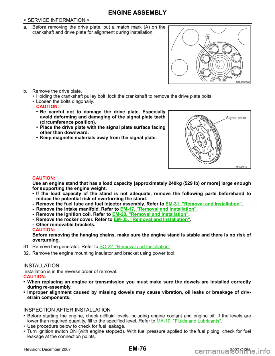
a. Before removing the drive plate, put a match mark (A) on the
crankshaft and drive plate for alignment during installation.
b. Remove the drive plate.
• Holding the crankshaft pulley bolt, lock the crankshaft to remove the drive plate bolts.
• Loosen the bolts diagonally.
CAUTION:
• Be careful not to damage the drive plate. Especially
avoid deforming and damaging of the signal plate teeth
(circumference position).
• Place the drive plate with the signal plate surface facing
other than downward.
• Keep magnetic materials away from the signal plate.
CAUTION:
Use an engine stand that has a load capacity [approximately 240kg (529 lb) or more] large enough
for supporting the engine weight.
• If the load capacity of the stand is not adequate, remove the following parts beforehand to
reduce the potential risk of overturning the stand.
- Remove the fuel tube and fuel injector assembly. Refer to EM-31, "
Removal and Installation".
- Remove the intake manifold. Refer to EM-17, "
Removal and Installation".
- Remove the ignition coil. Refer to EM-28, "
Removal and Installation".
- Remove the rocker cover. Refer to EM-35, "
Removal and Installation".
- Other removable brackets.
CAUTION:
Before removing the hanging chains, make sure the engine stand is stable and there is no risk of
overturning.
31. Remove the generator. Refer to SC-22, "
Removal and Installation".
32. Remove the engine mounting insulator and bracket using power tool.
INSTALLATION
Installation is in the reverse order of removal.
CAUTION:
• When replacing an engine or transmission you must make sure the dowels are installed correctly
during re-assembly.
• Improper alignment caused by missing dowels may cause vibration, oil leaks or breakage of driv-
etrain components.
INSPECTION AFTER INSTALLATION
• Before starting the engine, check oil/fluid levels including engine coolant and engine oil. If the levels are
lower than required quantity, fill to the specified level. Refer to MA-10, "
Fluids and Lubricants".
• Use procedure below to check for fuel leakage.
• Turn ignition switch ON (with engine stopped). With fuel pressure applied to the fuel piping, check for fuel
leakage at the connection points.
ALBIA0522ZZ
KBIA2491E