Page 2556 of 3061

RF-24
< SERVICE INFORMATION >
SUNROOF
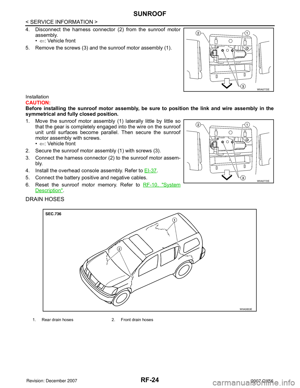
4. Disconnect the harness connector (2) from the sunroof motor
assembly.
•⇐: Vehicle front
5. Remove the screws (3) and the sunroof motor assembly (1).
Installation
CAUTION:
Before installing the sunroof motor assembly, be sure to position the link and wire assembly in the
symmetrical and fully closed position.
1. Move the sunroof motor assembly (1) laterally little by little so
that the gear is completely engaged into the wire on the sunroof
unit until surfaces become parallel. Then secure the sunroof
motor assembly with screws.
•⇐: Vehicle front
2. Secure the sunroof motor assembly (1) with screws (3).
3. Connect the harness connector (2) to the sunroof motor assem-
bly.
4. Install the overhead console assembly. Refer to EI-37
.
5. Connect the battery positive and negative cables.
6. Reset the sunroof motor memory. Refer to RF-10, "
System
Description".
DRAIN HOSES
WIIA0772E
WIIA0772E
1. Rear drain hoses 2. Front drain hoses
WIIA0853E
Page 2557 of 3061

SUNROOF
RF-25
< SERVICE INFORMATION >
C
D
E
F
G
H
J
K
L
MA
B
RF
N
O
P
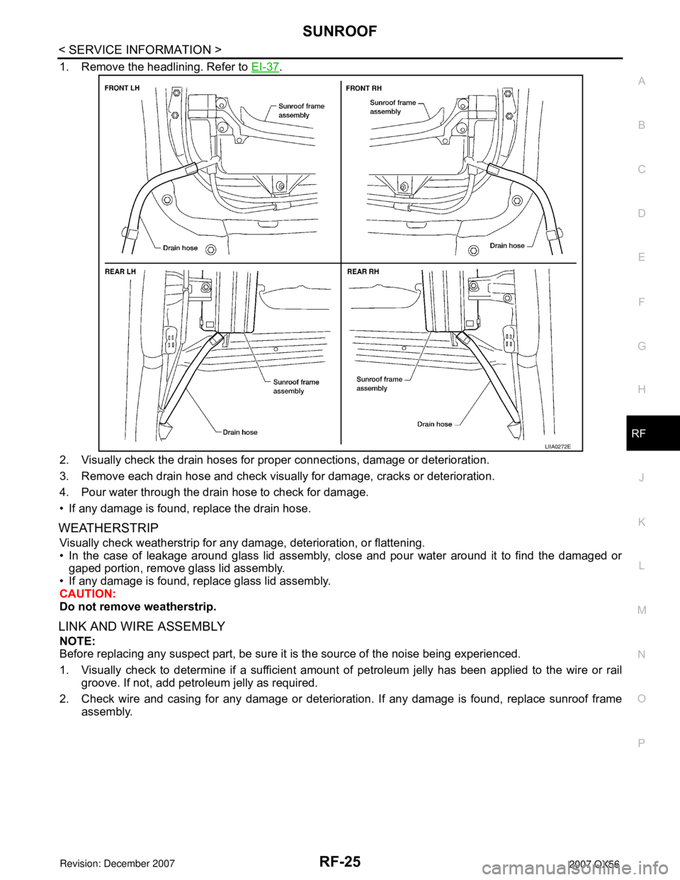
1. Remove the headlining. Refer to EI-37.
2. Visually check the drain hoses for proper connections, damage or deterioration.
3. Remove each drain hose and check visually for damage, cracks or deterioration.
4. Pour water through the drain hose to check for damage.
• If any damage is found, replace the drain hose.
WEATHERSTRIP
Visually check weatherstrip for any damage, deterioration, or flattening.
• In the case of leakage around glass lid assembly, close and pour water around it to find the damaged or
gaped portion, remove glass lid assembly.
• If any damage is found, replace glass lid assembly.
CAUTION:
Do not remove weatherstrip.
LINK AND WIRE ASSEMBLY
NOTE:
Before replacing any suspect part, be sure it is the source of the noise being experienced.
1. Visually check to determine if a sufficient amount of petroleum jelly has been applied to the wire or rail
groove. If not, add petroleum jelly as required.
2. Check wire and casing for any damage or deterioration. If any damage is found, replace sunroof frame
assembly.
LIIA0272E
Page 2559 of 3061

RFD-2
< SERVICE INFORMATION >
PRECAUTIONS
SERVICE INFORMATION
PRECAUTIONS
Precaution for Servicing Rear Final DriveINFOID:0000000003532597
• Before starting diagnosis of the vehicle, understand the symptoms well. Perform correct and systematic
operations.
• Check for the correct installation status prior to removal or disassembly. When matching marks are required,
be certain they do not interfere with the function of the parts they are applied to.
• Overhaul should be done in a clean work area, a dust proof area is recommended.
• Before disassembly, completely remove sand and mud from the exterior of the unit, preventing them from
entering into the unit during disassembly or assembly.
• Always use shop paper for cleaning the inside of components.
• Avoid using cotton gloves or a shop cloth to prevent the entering of lint.
• Check appearance of the disassembled parts for damage, deformation, and abnormal wear. Replace them
with new ones if necessary.
• Gaskets, seals and O-rings should be replaced any time the unit is disassembled.
• Clean and flush the parts sufficiently and blow them dry.
• Be careful not to damage sliding surfaces and mating surfaces.
• When applying sealant, remove the old sealant from the mating surface; then remove any moisture, oil, and
foreign materials from the application and mating surfaces.
• In principle, tighten nuts or bolts gradually in several steps working diagonally from inside to outside. If a
tightening sequence is specified, observe it.
• During assembly, observe the specified tightening torque.
• Add new differential gear oil, petroleum jelly, or multi-purpose grease, as specified.
Page 2643 of 3061
SEAT BELTS
SB-9
< SERVICE INFORMATION >
C
D
E
F
G
I
J
K
L
MA
B
SB
N
O
P
Third Row Center
REMOVAL
1. Remove the rear roof finisher. Refer to EI-39.
2. Lower the rear portion of the headliner.
3. Remove the seat belt retractor anchor bolts and retractor and belt assembly.
INSTALLATION
Installation is in the reverse order of removal.
THIRD ROW SEAT BELT BUCKLE
Removal
1. Place seatback RH/LH in the folded position.
2. Remove luggage floor board assembly and storage box. Refer to EI-39
.
3. Remove seat belt buckle bolt (2) from rear seat hinge (1).
•⇐: Vehicle front
WHIA0284E
Seat belt buckle bolt : 49 N·m (5.0 kg-m, 36 ft-lb)
LHIA0107E
Page 2680 of 3061

SE-8
< SERVICE INFORMATION >
SQUEAK AND RATTLE TROUBLE DIAGNOSIS
Most of these incidents can be repaired by adjusting, securing or insulating the item(s) or component(s) caus-
ing the noise.
SUNROOF/HEADLINING
Noises in the sunroof/headlining area can often be traced to one of the following:
1. Sunroof lid, rail, linkage or seals making a rattle or light knocking noise
2. Sun visor shaft shaking in the holder
3. Front or rear windshield touching headliner and squeaking
Again, pressing on the components to stop the noise while duplicating the conditions can isolate most of these
incidents. Repairs usually consist of insulating with felt cloth tape.
OVERHEAD CONSOLE (FRONT AND REAR)
Overhead console noises are often caused by the console panel clips not being engaged correctly. Most of
these incidents are repaired by pushing up on the console at the clip locations until the clips engage.
In addition look for:
1. Loose harness or harness connectors.
2. Front console map/reading lamp lense loose.
3. Loose screws at console attachment points.
SEATS
When isolating seat noise it's important to note the position the seat is in and the load placed on the seat when
the noise is present. These conditions should be duplicated when verifying and isolating the cause of the
noise.
Cause of seat noise include:
1. Headrest rods and holder
2. A squeak between the seat pad cushion and frame
3. The rear seatback lock and bracket
These noises can be isolated by moving or pressing on the suspected components while duplicating the con-
ditions under which the noise occurs. Most of these incidents can be repaired by repositioning the component
or applying urethane tape to the contact area.
UNDERHOOD
Some interior noise may be caused by components under the hood or on the engine wall. The noise is then
transmitted into the passenger compartment.
Causes of transmitted underhood noise include:
1. Any component mounted to the engine wall
2. Components that pass through the engine wall
3. Engine wall mounts and connectors
4. Loose radiator mounting pins
5. Hood bumpers out of adjustment
6. Hood striker out of adjustment
These noises can be difficult to isolate since they cannot be reached from the interior of the vehicle. The best
method is to secure, move or insulate one component at a time and test drive the vehicle. Also, engine RPM
or load can be changed to isolate the noise. Repairs can usually be made by moving, adjusting, securing, or
insulating the component causing the noise.