2007 INFINITI QX56 roof
[x] Cancel search: roofPage 1810 of 3061
EM-40
< SERVICE INFORMATION >
TIMING CHAIN
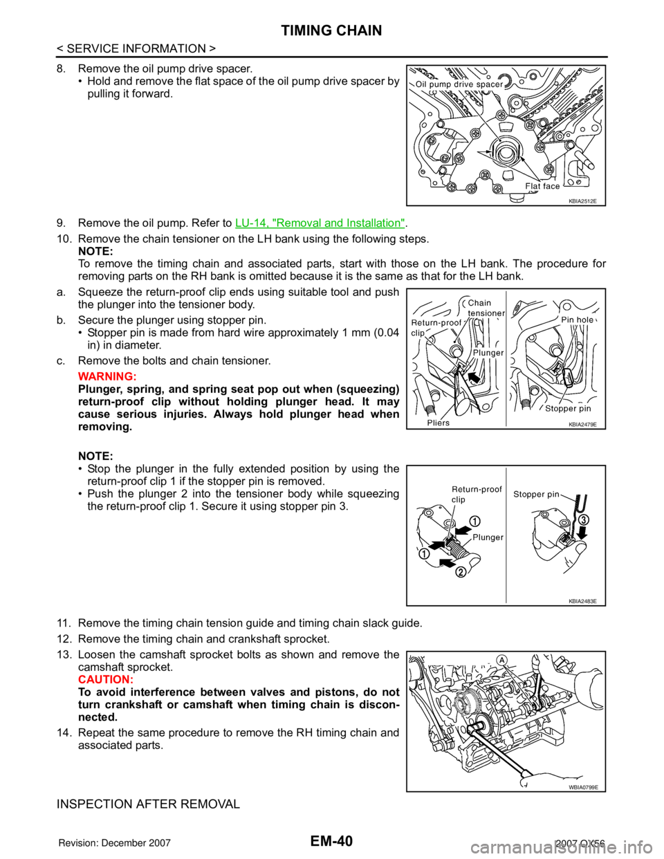
8. Remove the oil pump drive spacer.• Hold and remove the flat space of the oil pump drive spacer bypulling it forward.
9. Remove the oil pump. Refer to LU-14, "
Removal and Installation".
10. Remove the chain tensioner on the LH bank using the following steps. NOTE:
To remove the timing chain and associated parts, start with those on the LH bank. The procedure for
removing parts on the RH bank is omitted because it is the same as that for the LH bank.
a. Squeeze the return-proof clip ends using suitable tool and push the plunger into the tensioner body.
b. Secure the plunger using stopper pin. • Stopper pin is made from hard wire approximately 1 mm (0.04
in) in diameter.
c. Remove the bolts and chain tensioner.
WARNING:
Plunger, spring, and spring seat pop out when (squeezing)
return-proof clip without holding plunger head. It may
cause serious injuries. Alw ays hold plunger head when
removing.
NOTE:
• Stop the plunger in the fully extended position by using the return-proof clip 1 if the stopper pin is removed.
• Push the plunger 2 into the tensioner body while squeezing
the return-proof clip 1. Secure it using stopper pin 3.
11. Remove the timing chain tension guide and timing chain slack guide.
12. Remove the timing chain and crankshaft sprocket.
13. Loosen the camshaft sprocket bolts as shown and remove the camshaft sprocket.
CAUTION:
To avoid interference between valves and pistons, do not
turn crankshaft or camshaft wh en timing chain is discon-
nected.
14. Repeat the same procedure to remove the RH timing chain and associated parts.
INSPECTION AFTER REMOVAL
KBIA2512E
KBIA2479E
KBIA2483E
WBIA0799E
Page 1817 of 3061
CAMSHAFTEM-47
< SERVICE INFORMATION >
C
DE
F
G H
I
J
K L
M A
EM
NP
O
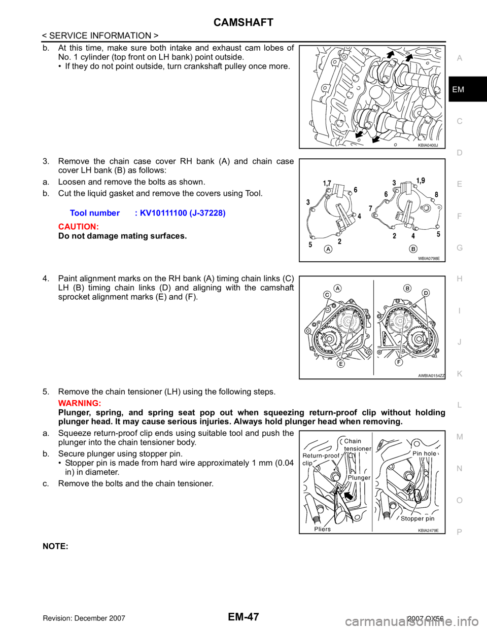
b. At this time, make sure both intake and exhaust cam lobes of
No. 1 cylinder (top front on LH bank) point outside.
• If they do not point outside, turn crankshaft pulley once more.
3. Remove the chain case cover RH bank (A) and chain case cover LH bank (B) as follows:
a. Loosen and remove the bolts as shown.
b. Cut the liquid gasket and remove the covers using Tool.
CAUTION:
Do not damage mating surfaces.
4. Paint alignment marks on the RH bank (A) timing chain links (C) LH (B) timing chain links (D) and aligning with the camshaft
sprocket alignment marks (E) and (F).
5. Remove the chain tensioner (LH) using the following steps. WARNING:
Plunger, spring, and spring seat pop out when squeezing return -proof clip without holding
plunger head. It may cause serious injuries. Always hold plunger head when removing.
a. Squeeze return-proof clip ends using suitable tool and push the plunger into the chain tensioner body.
b. Secure plunger using stopper pin. • Stopper pin is made from hard wire approximately 1 mm (0.04in) in diameter.
c. Remove the bolts and the chain tensioner.
NOTE:
KBIA0400J
Tool number : KV10111100 (J-37228)
WBIA0798E
AWBIA0154ZZ
KBIA2479E
Page 1818 of 3061
EM-48
< SERVICE INFORMATION >
CAMSHAFT
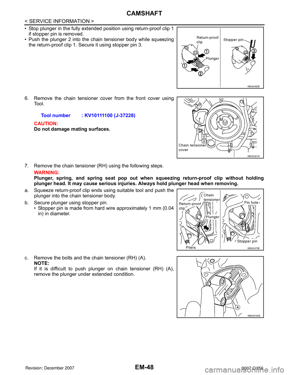
• Stop plunger in the fully extended position using return-proof clip 1if stopper pin is removed.
• Push the plunger 2 into the chain tensioner body while squeezing
the return-proof clip 1. Secure it using stopper pin 3.
6. Remove the chain tensioner cover from the front cover using Tool.
CAUTION:
Do not damage mating surfaces.
7. Remove the chain tensioner (RH) using the following steps. WARNING:
Plunger, spring, and spring seat pop out when squeezing return-proof clip without holding
plunger head. It may cause serious injuries. Always hold plunger head when removing.
a. Squeeze return-proof clip ends using suitable tool and push the plunger into the chain tensioner body.
b. Secure plunger using stopper pin. • Stopper pin is made from hard wire approximately 1 mm (0.04
in) in diameter.
c. Remove the bolts and the chain tensioner (RH) (A). NOTE:
If it is difficult to push plunger on chain tensioner (RH) (A),
remove the plunger under extended condition.
KBIA2483E
Tool number : KV10111100 (J-37228)
KBIA2521E
KBIA2479E
WBIA0705E
Page 1901 of 3061
FFD-2
< SERVICE INFORMATION >
PRECAUTIONS
SERVICE INFORMATION
PRECAUTIONS
Precaution for Servicing Front Final DriveINFOID:0000000003532584
• Before starting diagnosis of the vehicle, understand the symptoms well. Perform correct and systematic
operations.
• Check for the correct installation status prior to removal or disassembly. When matching marks are required,
be certain they do not interfere with the function of the parts they are applied to.
• Overhaul should be done in a clean work area, a dust proof area is recommended.
• Before disassembly, completely remove sand and mud from the exterior of the unit, preventing them from
entering into the unit during disassembly or assembly.
• Always use shop paper for cleaning the inside of components.
• Avoid using cotton gloves or a shop cloth to prevent the entering of lint.
• Check appearance of the disassembled parts for damage, deformation, and abnormal wear. Replace them
with new ones if necessary.
• Gaskets, seals and O-rings should be replaced any time the unit is disassembled.
• Clean and flush the parts sufficiently and blow them dry.
• Be careful not to damage sliding surfaces and mating surfaces.
• When applying sealant, remove the old sealant from the mating surface; then remove any moisture, oil, and
foreign materials from the application and mating surfaces.
• In principle, tighten nuts or bolts gradually in several steps working diagonally from inside to outside. If a
tightening sequence is specified, observe it.
• During assembly, observe the specified tightening torque.
• Add new differential gear oil, petroleum jelly, or multi-purpose grease, as specified.
Page 1935 of 3061
FL-4
< SERVICE INFORMATION >
FUEL SYSTEM
FUEL SYSTEM
Checking Fuel LineINFOID:0000000003532203
Inspect fuel lines, fuel filler cap and fuel tank for improper attach-
ment, leaks, cracks, damage, loose connections, chafing or deterio-
ration.
If necessary, repair or replace damaged parts.
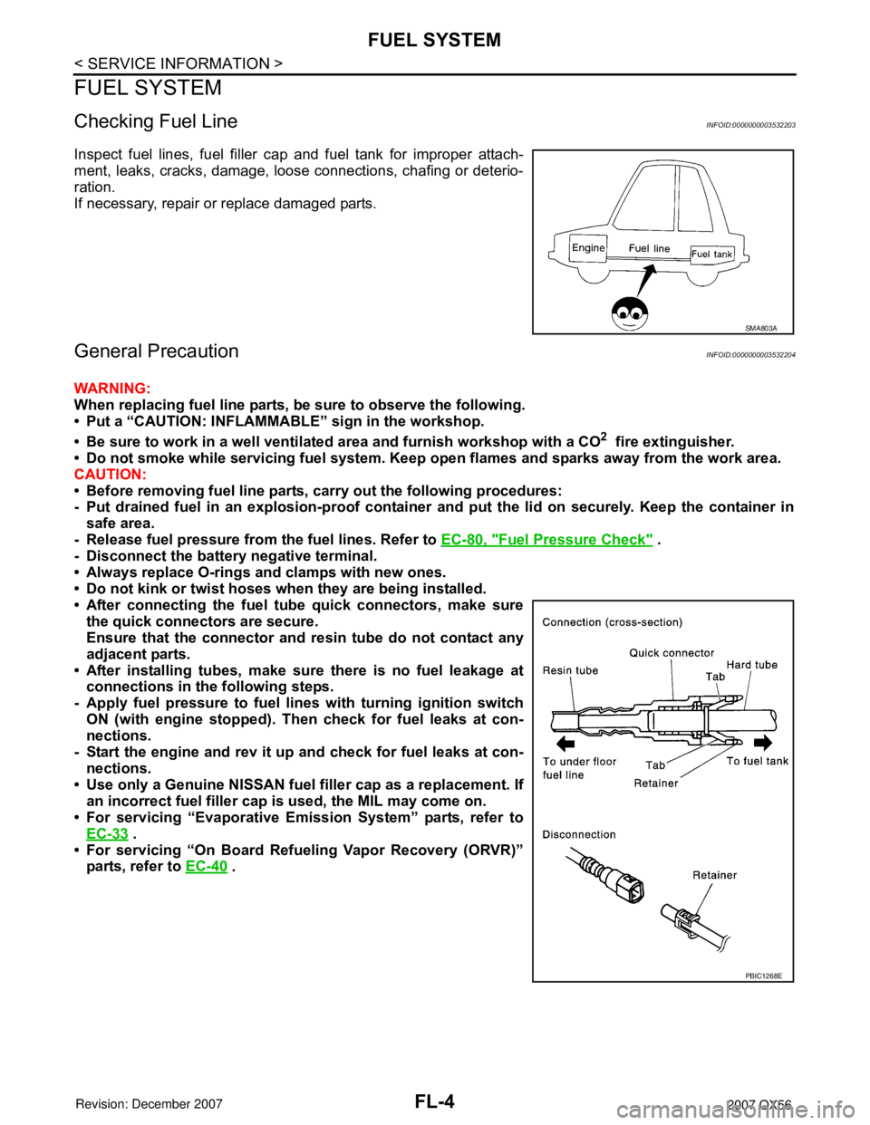
General PrecautionINFOID:0000000003532204
WARNING:
When replacing fuel line parts, be sure to observe the following.
• Put a “CAUTION: INFLAMMABLE” sign in the workshop.
• Be sure to work in a well ventilated area and furnish workshop with a CO
2 fire extinguisher.
• Do not smoke while servicing fuel system. Keep open flames and sparks away from the work area.
CAUTION:
• Before removing fuel line parts, carry out the following procedures:
- Put drained fuel in an explosion-proof container and put the lid on securely. Keep the container in
safe area.
- Release fuel pressure from the fuel lines. Refer to EC-80, "
Fuel Pressure Check" .
- Disconnect the battery negative terminal.
• Always replace O-rings and clamps with new ones.
• Do not kink or twist hoses when they are being installed.
• After connecting the fuel tube quick connectors, make sure
the quick connectors are secure.
Ensure that the connector and resin tube do not contact any
adjacent parts.
• After installing tubes, make sure there is no fuel leakage at
connections in the following steps.
- Apply fuel pressure to fuel lines with turning ignition switch
ON (with engine stopped). Then check for fuel leaks at con-
nections.
- Start the engine and rev it up and check for fuel leaks at con-
nections.
• Use only a Genuine NISSAN fuel filler cap as a replacement. If
an incorrect fuel filler cap is used, the MIL may come on.
• For servicing “Evaporative Emission System” parts, refer to
EC-33
.
• For servicing “On Board Refueling Vapor Recovery (ORVR)”
parts, refer to EC-40
.
SMA803A
PBIC1268E
Page 1988 of 3061
GI-22
< SERVICE INFORMATION >
SERVICE INFORMATION FOR ELECTRICAL INCIDENT
SERVICE INFORMATION FOR ELECTRICAL INCIDENT
How to Check TerminalINFOID:0000000003531487
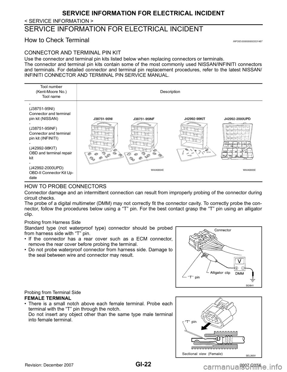
CONNECTOR AND TERMINAL PIN KIT
Use the connector and terminal pin kits listed below when replacing connectors or terminals.
The connector and terminal pin kits contain some of the most commonly used NISSAN/INFINITI connectors
and terminals. For detailed connector and terminal pin replacement procedures, refer to the latest NISSAN/
INFINITI CONNECTOR AND TERMINAL PIN SERVICE MANUAL.
HOW TO PROBE CONNECTORS
Connector damage and an intermittent connection can result from improperly probing of the connector during
circuit checks.
The probe of a digital multimeter (DMM) may not correctly fit the connector cavity. To correctly probe the con-
nector, follow the procedures below using a “T” pin. For the best contact grasp the “T” pin using an alligator
clip.
Probing from Harness Side
Standard type (not waterproof type) connector should be probed
from harness side with “T” pin.
• If the connector has a rear cover such as a ECM connector,
remove the rear cover before probing the terminal.
• Do not probe waterproof connector from harness side. Damage to
the seal between wire and connector may result.
Probing from Terminal Side
FEMALE TERMINAL
• There is a small notch above each female terminal. Probe each
terminal with the “T” pin through the notch.
Do not insert any object other than the same type male terminal
into female terminal.
Tool number
(Kent-Moore No.)
Tool nameDescription
-
(J38751-95NI)
Connector and terminal
pin kit (NISSAN)
-
(J38751-95INF)
Connector and terminal
pin kit (INFINITI)
-
(J42992-98KIT)
OBD and terminal repair
kit
-
(J42992-2000UPD)
OBD-II Connector Kit Up-
date
WAIA0004EWAIA0005E
SGI841
SEL265V
Page 1990 of 3061
GI-24
< SERVICE INFORMATION >
SERVICE INFORMATION FOR ELECTRICAL INCIDENT
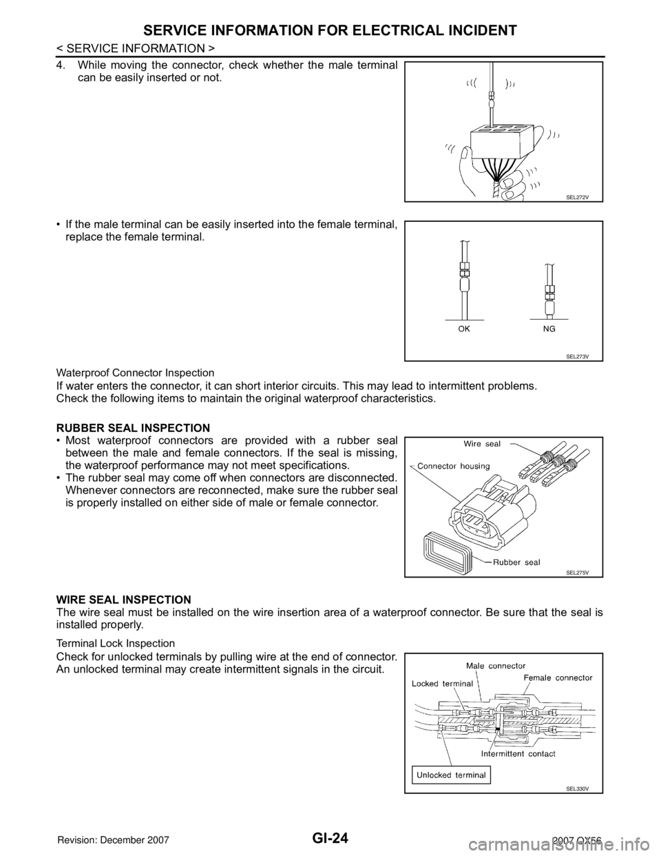
4. While moving the connector, check whether the male terminal
can be easily inserted or not.
• If the male terminal can be easily inserted into the female terminal,
replace the female terminal.
Waterproof Connector Inspection
If water enters the connector, it can short interior circuits. This may lead to intermittent problems.
Check the following items to maintain the original waterproof characteristics.
RUBBER SEAL INSPECTION
• Most waterproof connectors are provided with a rubber seal
between the male and female connectors. If the seal is missing,
the waterproof performance may not meet specifications.
• The rubber seal may come off when connectors are disconnected.
Whenever connectors are reconnected, make sure the rubber seal
is properly installed on either side of male or female connector.
WIRE SEAL INSPECTION
The wire seal must be installed on the wire insertion area of a waterproof connector. Be sure that the seal is
installed properly.
Terminal Lock Inspection
Check for unlocked terminals by pulling wire at the end of connector.
An unlocked terminal may create intermittent signals in the circuit.
SEL272V
SEL273V
SEL275V
SEL330V
Page 2014 of 3061
GI-48
< SERVICE INFORMATION >
IDENTIFICATION INFORMATION
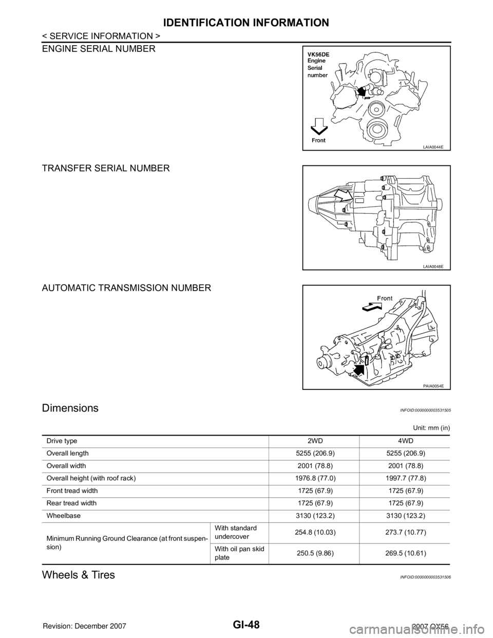
ENGINE SERIAL NUMBER
TRANSFER SERIAL NUMBER
AUTOMATIC TRANSMISSION NUMBER
DimensionsINFOID:0000000003531505
Unit: mm (in)
Wheels & TiresINFOID:0000000003531506
LAIA0044E
LAIA0048E
PAIA0054E
Drive type2WD 4WD
Overall length 5255 (206.9) 5255 (206.9)
Overall width 2001 (78.8) 2001 (78.8)
Overall height (with roof rack) 1976.8 (77.0) 1997.7 (77.8)
Front tread width 1725 (67.9) 1725 (67.9)
Rear tread width 1725 (67.9) 1725 (67.9)
Wheelbase 3130 (123.2) 3130 (123.2)
Minimum Running Ground Clearance (at front suspen-
sion)With standard
undercover254.8 (10.03) 273.7 (10.77)
With oil pan skid
plate250.5 (9.86) 269.5 (10.61)