2007 INFINITI QX56 roof
[x] Cancel search: roofPage 2533 of 3061
RF-1
BODY
C
D
E
F
G
H
J
K
L
M
SECTION RF
A
B
RF
N
O
P
CONTENTS
ROOF
SERVICE INFORMATION ............................2
PRECAUTIONS ...................................................2
Precaution for Supplemental Restraint System
(SRS) "AIR BAG" and "SEAT BELT PRE-TEN-
SIONER" ...................................................................
2
Precaution .................................................................2
PREPARATION ...................................................3
Special Service Tool .................................................3
Commercial Service Tool ..........................................3
SQUEAK AND RATTLE TROUBLE DIAGNO-
SIS .......................................................................
4
Work Flow .................................................................4
Generic Squeak and Rattle Troubleshooting ............6
Diagnostic Worksheet ...............................................8
SUNROOF ..........................................................10
Component Parts and Harness Connector Loca-
tion ..........................................................................
10
System Description .................................................10
CAN Communication System Description ...............11
Wiring Diagram - SROOF - ......................................12
Terminal and Reference Value for BCM ..................13
Sunroof Motor Assembly Harness Connector Ter-
minal Layout ............................................................
14
Terminal and Reference Value for Sunroof Motor
Assembly .................................................................
14
Work Flow ................................................................14
CONSULT-II Function (BCM) ..................................14
Work Support ...........................................................15
Active Test ...............................................................15
Data Monitor ............................................................15
Trouble Diagnosis Chart by Symptom .....................15
BCM Power Supply and Ground Circuit Inspection
....
16
Sunroof Switch System Inspection ..........................16
Sunroof Motor Assembly Power Supply and
Ground Circuit Inspection ........................................
16
Door Switch Check ..................................................18
Fitting Adjustment ....................................................20
Removal and Installation .........................................20
Page 2539 of 3061
SQUEAK AND RATTLE TROUBLE DIAGNOSIS
RF-7
< SERVICE INFORMATION >
C
D
E
F
G
H
J
K
L
MA
B
RF
N
O
P
Most of these incidents can be repaired by adjusting, securing or insulating the item(s) or component(s) caus-
ing the noise.
SUNROOF/HEADLINING
Noises in the sunroof/headlining area can often be traced to one of the following:
1. Sunroof lid, rail, linkage or seals making a rattle or light knocking noise
2. Sun visor shaft shaking in the holder
3. Front or rear windshield touching headliner and squeaking
Again, pressing on the components to stop the noise while duplicating the conditions can isolate most of these
incidents. Repairs usually consist of insulating with felt cloth tape.
OVERHEAD CONSOLE (FRONT AND REAR)
Overhead console noises are often caused by the console panel clips not being engaged correctly. Most of
these incidents are repaired by pushing up on the console at the clip locations until the clips engage.
In addition look for:
1. Loose harness or harness connectors.
2. Front console map/reading lamp lens loose.
3. Loose screws at console attachment points.
SEATS
When isolating seat noise it's important to note the position the seat is in and the load placed on the seat when
the noise is present. These conditions should be duplicated when verifying and isolating the cause of the
noise.
Cause of seat noise include:
1. Headrest rods and holder
2. A squeak between the seat pad cushion and frame
3. The rear seatback lock and bracket
These noises can be isolated by moving or pressing on the suspected components while duplicating the con-
ditions under which the noise occurs. Most of these incidents can be repaired by repositioning the component
or applying urethane tape to the contact area.
UNDERHOOD
Some interior noise may be caused by components under the hood or on the engine wall. The noise is then
transmitted into the passenger compartment.
Causes of transmitted underhood noise include:
1. Any component installed to the engine wall
2. Components that pass through the engine wall
3. Engine wall mounts and connectors
4. Loose radiator installation pins
5. Hood bumpers out of adjustment
6. Hood striker out of adjustment
These noises can be difficult to isolate since they cannot be reached from the interior of the vehicle. The best
method is to secure, move or insulate one component at a time and test drive the vehicle. Also, engine RPM
or load can be changed to isolate the noise. Repairs can usually be made by moving, adjusting, securing, or
insulating the component causing the noise.
Page 2542 of 3061
RF-10
< SERVICE INFORMATION >
SUNROOF
SUNROOF
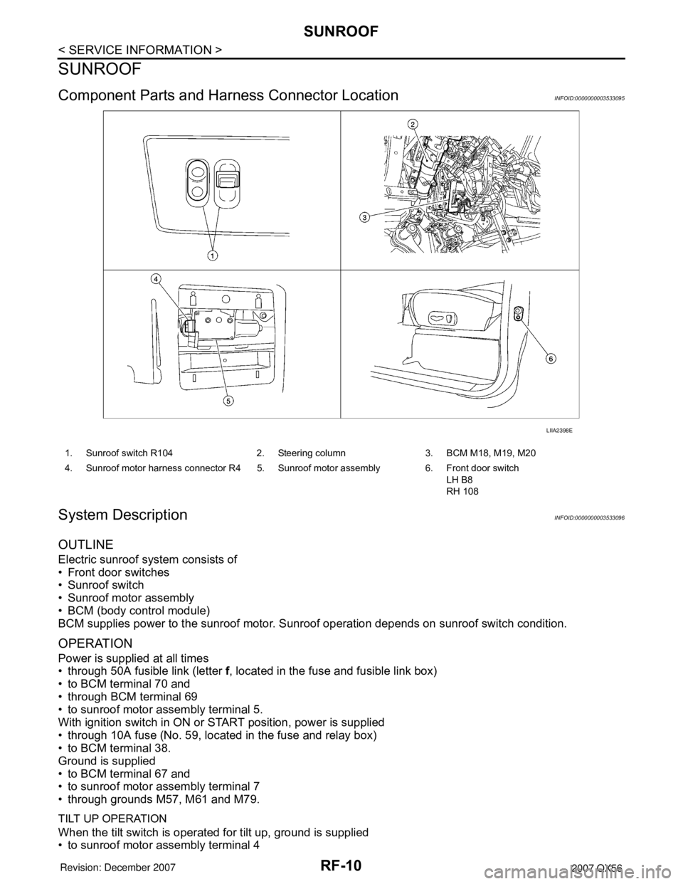
Component Parts and Harness Connector LocationINFOID:0000000003533095
System DescriptionINFOID:0000000003533096
OUTLINE
Electric sunroof system consists of
• Front door switches
• Sunroof switch
• Sunroof motor assembly
• BCM (body control module)
BCM supplies power to the sunroof motor. Sunroof operation depends on sunroof switch condition.
OPERATION
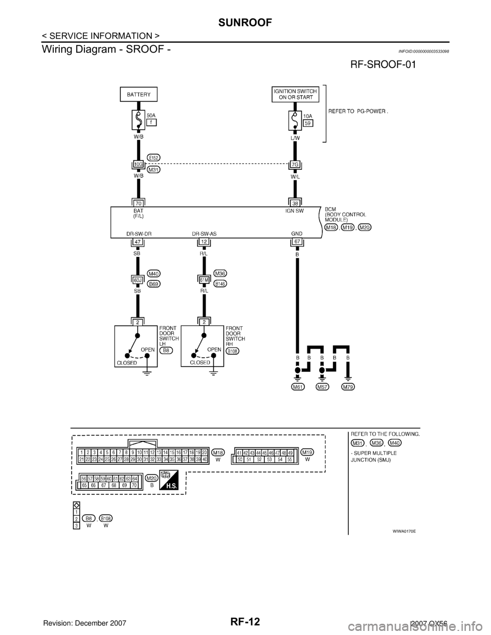
Power is supplied at all times
• through 50A fusible link (letter f, located in the fuse and fusible link box)
• to BCM terminal 70 and
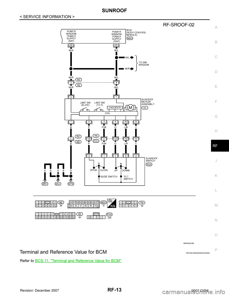
• through BCM terminal 69
• to sunroof motor assembly terminal 5.
With ignition switch in ON or START position, power is supplied
• through 10A fuse (No. 59, located in the fuse and relay box)
• to BCM terminal 38.
Ground is supplied
• to BCM terminal 67 and
• to sunroof motor assembly terminal 7
• through grounds M57, M61 and M79.
TILT UP OPERATION
When the tilt switch is operated for tilt up, ground is supplied
• to sunroof motor assembly terminal 4
LIIA2398E
1. Sunroof switch R104 2. Steering column 3. BCM M18, M19, M20
4. Sunroof motor harness connector R4 5. Sunroof motor assembly 6. Front door switch
LH B8
RH 108
Page 2543 of 3061
SUNROOF
RF-11
< SERVICE INFORMATION >
C
D
E
F
G
H
J
K
L
MA
B
RF
N
O
P
• through sunroof switch terminal 4
• through sunroof switch terminal 2
• through sunroof motor assembly terminal 8
• through grounds M57, M61 and M79.
Then, the sunroof will tilt up.
TILT DOWN OPERATION
When the tilt switch is operated for tilt down, ground is supplied
• to sunroof motor assembly terminal 10
• through sunroof switch terminal 6
• through sunroof switch terminal 2
• through sunroof motor assembly terminal 8
• through grounds M57, M61 and M79.
Then, the sunroof will tilt down.
SLIDE OPEN OPERATION
When the switch is operated for slide open, ground is supplied
• to sunroof motor assembly terminal 9
• through sunroof switch terminal 3
• through sunroof switch terminal 2
• through sunroof motor assembly terminal 8
• through grounds M57, M61 and M79.
Then, the sunroof will slide open.
SLIDE CLOSE OPERATION
When the switch is operated for slide close, ground is supplied
• to sunroof motor assembly terminal 3
• through sunroof switch terminal 1
• through sunroof switch terminal 2
• through sunroof motor assembly terminal 8
• through grounds M57, M61 and M79.
Then, the sunroof will slide closed.
RETAINED POWER OPERATION
When the ignition switch is turned to OFF position from ON or START position, power is supplied for 45 sec-
onds.
The retained power operation is canceled when the driver or passenger side door is opened.
RAP signal period can be changed by CONSULT-II. Refer to RF-14, "
CONSULT-II Function (BCM)".
MEMORY RESET PROCEDURE
To reset the sunroof motor memory from any sunroof position (full open, partially open, closed, partially
vented, and vented), push and hold the sunroof tilt switch in the forward (DOWN) position until the sunroof is
fully closed. After it has closed all the way, push and hold the tilt switch forward (DOWN) for more than 2 sec-
onds to re-establish the motor preset position. The sunroof should now operate normally.
INTERRUPTION DETECTION FUNCTION
The CPU (central processing unit) monitors the sunroof motor operation and the sunroof position (fully-closed
or other) by the signals from the sunroof motor.
When sunroof motor detects an interruption during the following sliding close operations, sunroof switch con-
trols the motor for open and the sunroof will operate until it reaches full open position.
• automatic close operation when ignition switch is in the ON position.
• automatic close operation during retained power operation.
CAN Communication System DescriptionINFOID:0000000003533097
Refer to LAN-4.
Page 2544 of 3061
RF-12
< SERVICE INFORMATION >
SUNROOF
Wiring Diagram - SROOF -
INFOID:0000000003533098
WIWA0170E
Page 2545 of 3061
SUNROOF
RF-13
< SERVICE INFORMATION >
C
D
E
F
G
H
J
K
L
MA
B
RF
N
O
P
Terminal and Reference Value for BCMINFOID:0000000003533099
Refer to BCS-11, "Terminal and Reference Value for BCM".
WIWA0318E
Page 2546 of 3061
RF-14
< SERVICE INFORMATION >
SUNROOF
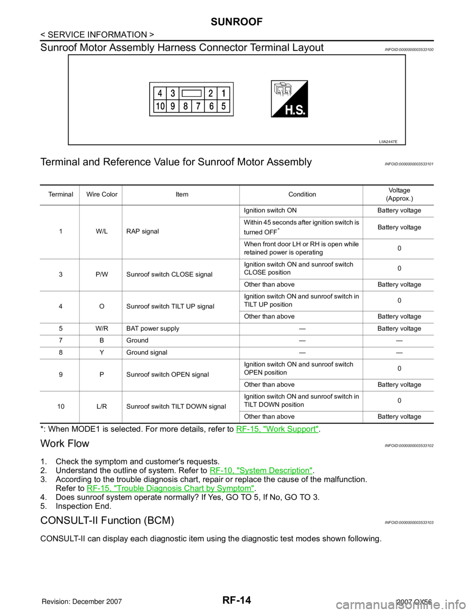
Sunroof Motor Assembly Harness Connector Terminal Layout
INFOID:0000000003533100
Terminal and Reference Value for Sunroof Motor AssemblyINFOID:0000000003533101
*: When MODE1 is selected. For more details, refer to RF-15, "Work Support".
Work FlowINFOID:0000000003533102
1. Check the symptom and customer's requests.
2. Understand the outline of system. Refer to RF-10, "
System Description".
3. According to the trouble diagnosis chart, repair or replace the cause of the malfunction.
Refer to RF-15, "
Trouble Diagnosis Chart by Symptom".
4. Does sunroof system operate normally? If Yes, GO TO 5, If No, GO TO 3.
5. Inspection End.
CONSULT-II Function (BCM)INFOID:0000000003533103
CONSULT-II can display each diagnostic item using the diagnostic test modes shown following.
LIIA2447E
Terminal Wire Color Item ConditionVol tag e
(Approx.)
1 W/L RAP signalIgnition switch ON Battery voltage
Within 45 seconds after ignition switch is
turned OFF
*Battery voltage
When front door LH or RH is open while
retained power is operating0
3 P/W Sunroof switch CLOSE signalIgnition switch ON and sunroof switch
CLOSE position0
Other than above Battery voltage
4 O Sunroof switch TILT UP signalIgnition switch ON and sunroof switch in
TILT UP position0
Other than above Battery voltage
5 W/R BAT power supply — Battery voltage
7 B Ground — —
8 Y Ground signal — —
9 P Sunroof switch OPEN signalIgnition switch ON and sunroof switch
OPEN position0
Other than above Battery voltage
10 L/R Sunroof switch TILT DOWN signalIgnition switch ON and sunroof switch in
TILT DOWN position0
Other than above Battery voltage
Page 2547 of 3061
SUNROOF
RF-15
< SERVICE INFORMATION >
C
D
E
F
G
H
J
K
L
MA
B
RF
N
O
P
CONSULT-II START PROCEDURE
Refer to GI-36, "CONSULT-II Start Procedure".
Work SupportINFOID:0000000003533104
Active TestINFOID:0000000003533105
Data MonitorINFOID:0000000003533106
Trouble Diagnosis Chart by SymptomINFOID:0000000003533107
BCM diagnostic
test itemDiagnostic mode Description
Inspection by partWORK SUPPORTSupports inspections and adjustments. Commands are transmitted to the BCM for
setting the status suitable for required operation, input/output signals are received
from the BCM and received data is displayed.
DATA MONITOR Displays BCM input/output data in real time.
ACTIVE TEST Operation of electrical loads can be checked by sending drive signal to them.
SELF-DIAG RESULTS Displays BCM self-diagnosis results.
CAN DIAG SUPPORT MNTR The result of transmit/receive diagnosis of CAN communication can be read.
ECU PART NUMBER BCM part number can be read.
CONFIGURATION Performs BCM configuration read/write functions.
Work item Description
RETAINED PWR SETRAP signal’s power supply period can be changed by mode setting. Selects RAP sig-
nal’s power supply period between the following three steps:
• MODE 1 (45 sec.) / MODE 2 (OFF) / MODE 3 (2 min.)
Test item Description
RETAINED PWRThis test is able to supply RAP signal (power) from BCM to power window system,
power sunroof system. Those systems can be operated when turning on "RETAINED
PWR" on CONSULT-II screen even if the ignition switch is turned OFF.
NOTE:
During this test, CONSULT-II can be operated with ignition switch in "OFF" posi-
tion. "RETAINED PWR" should be turned "ON" or "OFF" on CONSULT-II screen
when ignition switch ON. Then turn ignition switch OFF for checking retained
power operation. CONSULT-II might be stuck if "RETAINED PWR" is turned "ON"
or "OFF" on CONSULT-II screen when ignition switch is OFF.
Monitored item Description
IGN ON SW Indicates [ON/OFF] condition of ignition switch.
DOOR SW-DR Indicates [ON/OFF] condition of front door switch driver side.
DOOR SW-AS Indicates [ON/OFF] condition of front door switch passenger side.
Symptom Diagnostic procedure and repair order Refer to page
Sunroof does not operate.1. Sunroof motor assembly power supply and ground cir-
cuit checkRF-16
2. Sunroof switch system checkRF-16
3. BCM power supply and ground circuit checkBCS-15
4. Replace sunroof motor assemblyRF-20