2007 INFINITI QX56 tow
[x] Cancel search: towPage 2329 of 3061
LT-122
< SERVICE INFORMATION >
ILLUMINATION
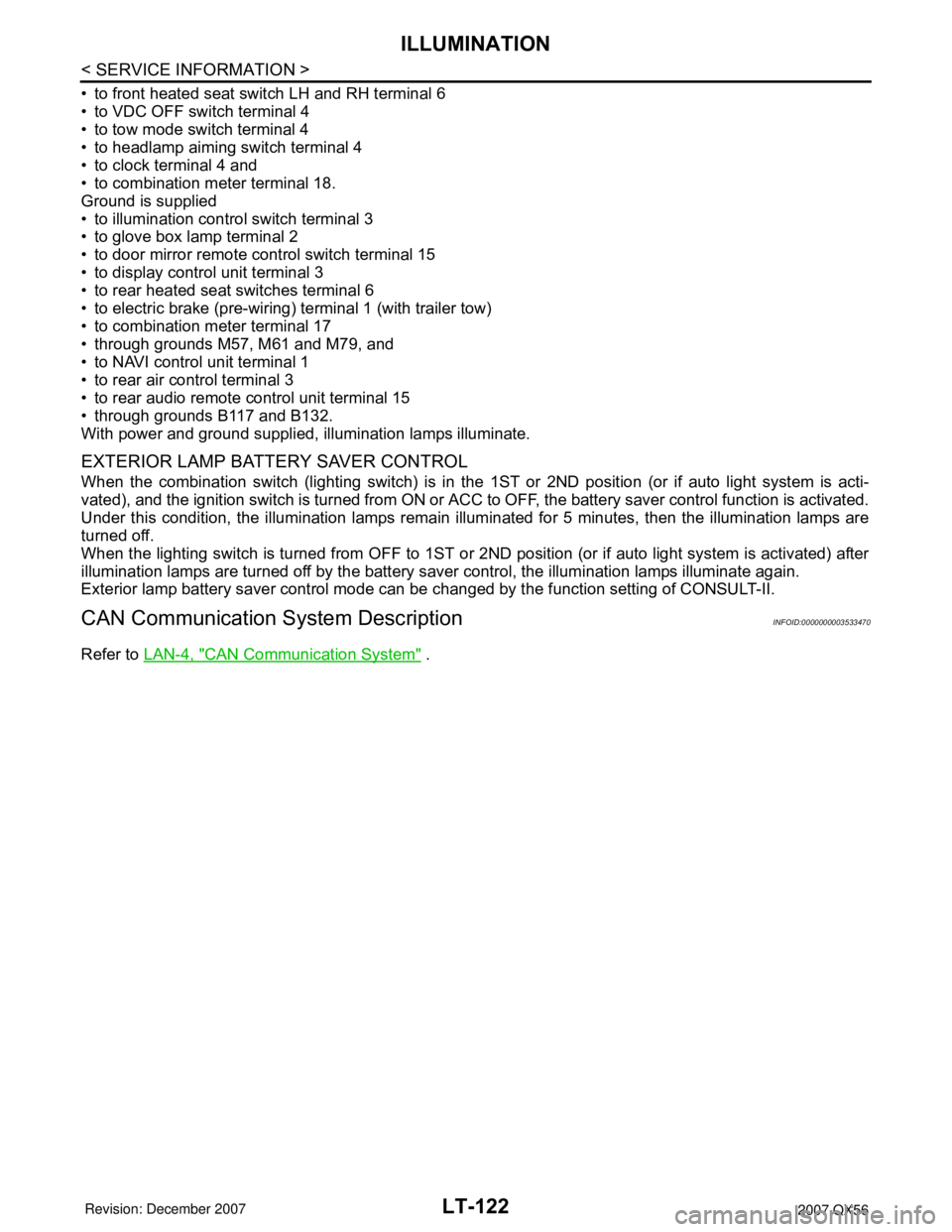
• to front heated seat switch LH and RH terminal 6
• to VDC OFF switch terminal 4
• to tow mode switch terminal 4
• to headlamp aiming switch terminal 4
• to clock terminal 4 and
• to combination meter terminal 18.
Ground is supplied
• to illumination control switch terminal 3
• to glove box lamp terminal 2
• to door mirror remote control switch terminal 15
• to display control unit terminal 3
• to rear heated seat switches terminal 6
• to electric brake (pre-wiring) terminal 1 (with trailer tow)
• to combination meter terminal 17
• through grounds M57, M61 and M79, and
• to NAVI control unit terminal 1
• to rear air control terminal 3
• to rear audio remote control unit terminal 15
• through grounds B117 and B132.
With power and ground supplied, illumination lamps illuminate.
EXTERIOR LAMP BATTERY SAVER CONTROL
When the combination switch (lighting switch) is in the 1ST or 2ND position (or if auto light system is acti-
vated), and the ignition switch is turned from ON or ACC to OFF, the battery saver control function is activated.
Under this condition, the illumination lamps remain illuminated for 5 minutes, then the illumination lamps are
turned off.
When the lighting switch is turned from OFF to 1ST or 2ND position (or if auto light system is activated) after
illumination lamps are turned off by the battery saver control, the illumination lamps illuminate again.
Exterior lamp battery saver control mode can be changed by the function setting of CONSULT-II.
CAN Communication System DescriptionINFOID:0000000003533470
Refer to LAN-4, "CAN Communication System" .
Page 2368 of 3061
MA-6
< SERVICE INFORMATION >
PERIODIC MAINTENANCE
PERIODIC MAINTENANCE
Introduction of Periodic MaintenanceINFOID:0000000003533860
Two different maintenance schedules are provided, and should be used, depending upon the conditions in
which the vehicle is mainly operated. After 60,000 miles (96,000 km) or 48 months, continue the periodic
maintenance at the same mileage or time intervals, whichever comes first.
Maintenance for Off-road Driving (4WD only)INFOID:0000000003533861
After driving the vehicle off-road through sand, mud, or water; more frequent maintenance may be required for
the following items:
Brake pads and rotors
Brake lines and hoses
Rear final drive oil, transmission fluid, and transfer fluid
Steering linkage
Drive shafts
Engine air cleaner filter
In-cabin microfilters
Schedule 1INFOID:0000000003533862
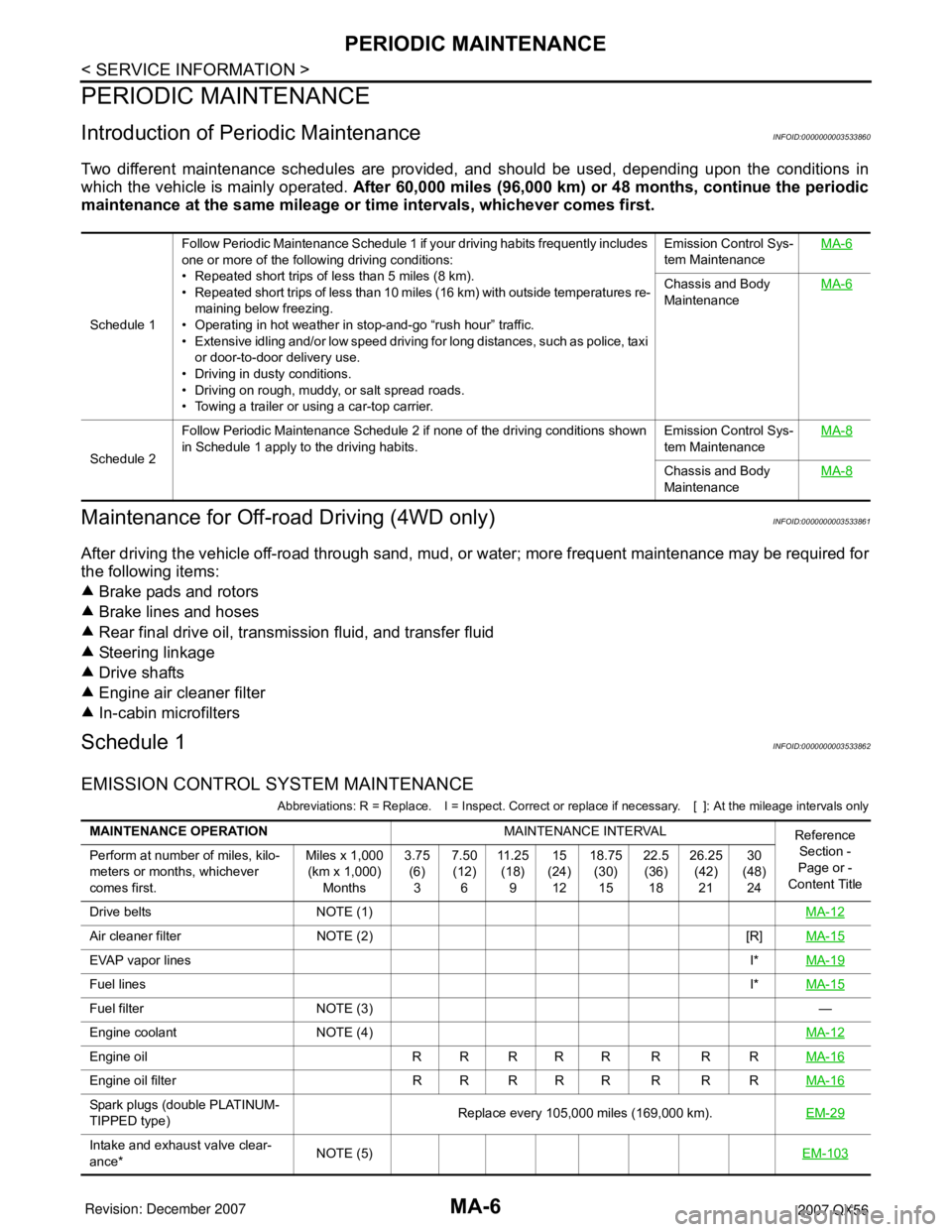
EMISSION CONTROL SYSTEM MAINTENANCE
Abbreviations: R = Replace. I = Inspect. Correct or replace if necessary. [ ]: At the mileage intervals only
Schedule 1Follow Periodic Maintenance Schedule 1 if your driving habits frequently includes
one or more of the following driving conditions:
• Repeated short trips of less than 5 miles (8 km).
• Repeated short trips of less than 10 miles (16 km) with outside temperatures re-
maining below freezing.
• Operating in hot weather in stop-and-go “rush hour” traffic.
• Extensive idling and/or low speed driving for long distances, such as police, taxi
or door-to-door delivery use.
• Driving in dusty conditions.
• Driving on rough, muddy, or salt spread roads.
• Towing a trailer or using a car-top carrier.Emission Control Sys-
tem MaintenanceMA-6
Chassis and Body
MaintenanceMA-6
Schedule 2Follow Periodic Maintenance Schedule 2 if none of the driving conditions shown
in Schedule 1 apply to the driving habits.Emission Control Sys-
tem MaintenanceMA-8Chassis and Body
MaintenanceMA-8
MAINTENANCE OPERATIONMAINTENANCE INTERVAL
Reference
Section -
Page or -
Content Title Perform at number of miles, kilo-
meters or months, whichever
comes first.Miles x 1,000
(km x 1,000)
Months3.75
(6)
37.50
(12)
611 . 2 5
(18)
915
(24)
1218.75
(30)
1522.5
(36)
1826.25
(42)
2130
(48)
24
Drive belts NOTE (1)MA-12
Air cleaner filter NOTE (2) [R]MA-15
EVAP vapor linesI*MA-19
Fuel linesI*MA-15
Fuel filter NOTE (3)—
Engine coolant NOTE (4)MA-12
Engine oil R R R R R R R RMA-16
Engine oil filter R R R R R R R RMA-16
Spark plugs (double PLATINUM-
TIPPED type)Replace every 105,000 miles (169,000 km).EM-29
Intake and exhaust valve clear-
ance*NOTE (5)EM-103
Page 2370 of 3061
MA-8
< SERVICE INFORMATION >
PERIODIC MAINTENANCE
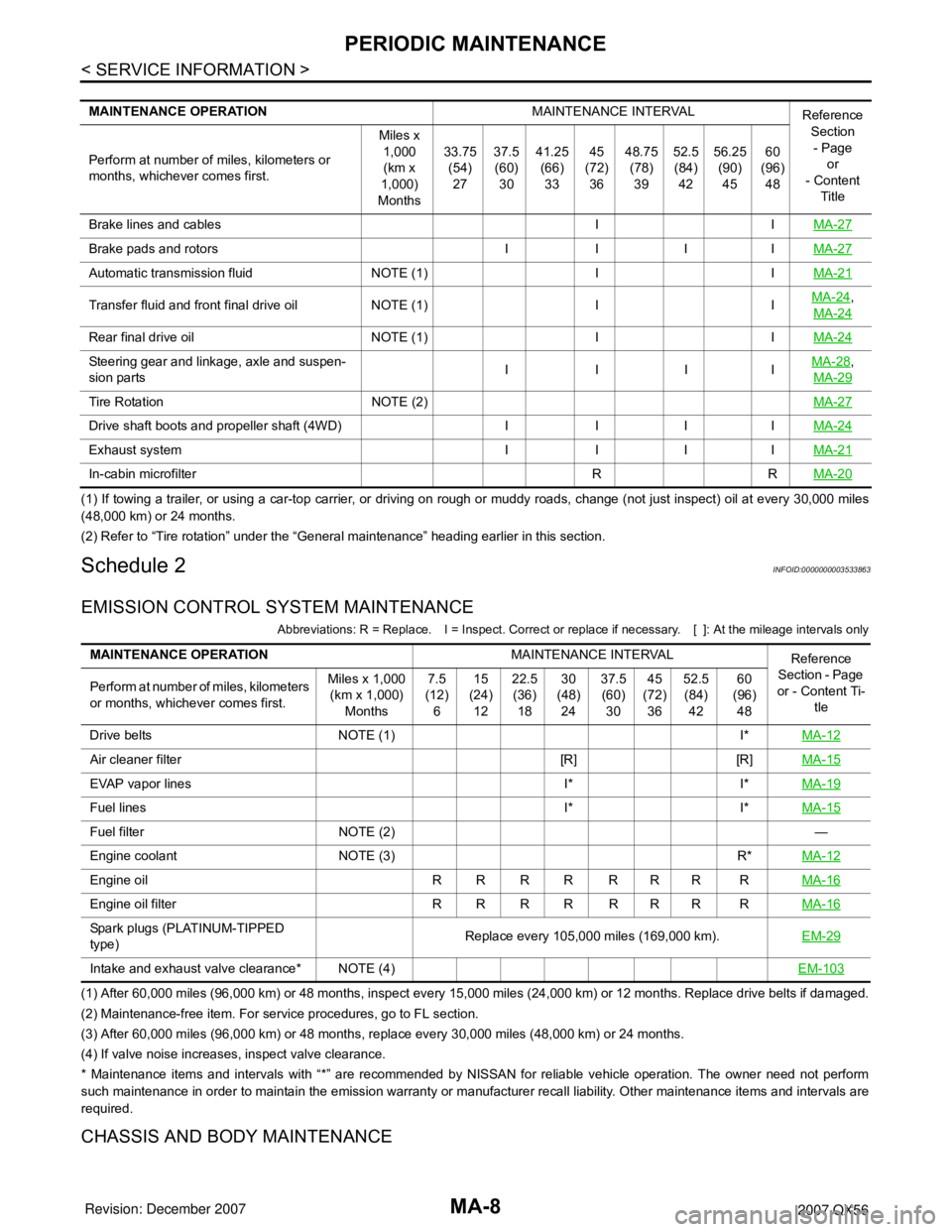
(1) If towing a trailer, or using a car-top carrier, or driving on rough or muddy roads, change (not just inspect) oil at every 30,000 miles
(48,000 km) or 24 months.
(2) Refer to “Tire rotation” under the “General maintenance” heading earlier in this section.
Schedule 2INFOID:0000000003533863
EMISSION CONTROL SYSTEM MAINTENANCE
Abbreviations: R = Replace. I = Inspect. Correct or replace if necessary. [ ]: At the mileage intervals only
(1) After 60,000 miles (96,000 km) or 48 months, inspect every 15,000 miles (24,000 km) or 12 months. Replace drive belts if damaged.
(2) Maintenance-free item. For service procedures, go to FL section.
(3) After 60,000 miles (96,000 km) or 48 months, replace every 30,000 miles (48,000 km) or 24 months.
(4) If valve noise increases, inspect valve clearance.
* Maintenance items and intervals with “*” are recommended by NISSAN for reliable vehicle operation. The owner need not perform
such maintenance in order to maintain the emission warranty or manufacturer recall liability. Other maintenance items and intervals are
required.
CHASSIS AND BODY MAINTENANCE
MAINTENANCE OPERATIONMAINTENANCE INTERVAL
Reference
Section
- Page
or
- Content
Title Perform at number of miles, kilometers or
months, whichever comes first.Miles x
1,000
(km x
1,000)
Months33.75
(54)
2737.5
(60)
3041.25
(66)
3345
(72)
3648.75
(78)
3952.5
(84)
4256.25
(90)
4560
(96)
48
Brake lines and cables I IMA-27
Brake pads and rotors I I I IMA-27
Automatic transmission fluid NOTE (1) I IMA-21
Transfer fluid and front final drive oil NOTE (1) I IMA-24,
MA-24
Rear final drive oil NOTE (1) I IMA-24
Steering gear and linkage, axle and suspen-
sion partsIIIIMA-28,
MA-29
Tire Rotation NOTE (2)MA-27
Drive shaft boots and propeller shaft (4WD) I I I IMA-24
Exhaust system I I I IMA-21
In-cabin microfilter R RMA-20
MAINTENANCE OPERATIONMAINTENANCE INTERVAL
Reference
Section - Page
or - Content Ti-
tle Perform at number of miles, kilometers
or months, whichever comes first.Miles x 1,000
(km x 1,000)
Months7.5
(12)
615
(24)
1222.5
(36)
1830
(48)
2437.5
(60)
3045
(72)
3652.5
(84)
4260
(96)
48
Drive belts NOTE (1) I*MA-12
Air cleaner filter [R] [R]MA-15
EVAP vapor lines I* I*MA-19
Fuel lines I* I*MA-15
Fuel filter NOTE (2) —
Engine coolant NOTE (3) R*MA-12
Engine oil R R R R R R R RMA-16
Engine oil filter R R R R R R R RMA-16
Spark plugs (PLATINUM-TIPPED
type)Replace every 105,000 miles (169,000 km).EM-29
Intake and exhaust valve clearance* NOTE (4)EM-103
Page 2426 of 3061

PG-24
< SERVICE INFORMATION >
IPDM E/R (INTELLIGENT POWER DISTRIBUTION MODULE ENGINE ROOM)
43 L/Y Wiper auto stop signal InputON or
STARTWiper switch OFF, LO, INT Battery voltage
44 BRDaytime light relay
controlInput ONDaytime light system active 0V
Daytime light system inactive Battery voltage
45 G/W Horn relay control Input ONWhen door locks are operated
using key fob (OFF → ON)*1Battery voltage → 0V
46 GRFuel pump relay con-
trolInput —Ignition switch ON or START 0V
Ignition switch OFF or ACC Battery voltage
47 OThrottle control motor
relay controlInput —Ignition switch ON or START 0V
Ignition switch OFF or ACC Battery voltage
48 B/RStarter relay (inhibit
switch)InputON or
STARTSelector lever in "P" or "N" 0V
Selector lever any other posi-
tionBattery voltage
49 R/L Trailer tow relay Output ONLighting
switch must
be in the 1st
positionOFF 0V
ON Battery voltage
50 W/R Front fog lamp (LH) OutputON or
STARTLighting
switch must
be in the 2nd
position
(LOW beam
is ON) and
the front fog
lamp switchOFF 0V
ON Battery voltage
51 W/R Front fog lamp (RH) OutputON or
STARTLighting
switch must
be in the 2nd
position
(LOW beam
is ON) and
the front fog
lamp switchOFF 0V
ON Battery voltage
52 LLH low beam head-
lampOutput — Lighting switch in 2nd position Battery voltage
54 R/YRH low beam head-
lampOutput — Lighting switch in 2nd position Battery voltage
55 GLH high beam head-
lampOutput —Lighting switch in 2nd position
and placed in HIGH or PASS
positionBattery voltage
56L/W*2
Y*3LH high beam head-
lampOutput —Lighting switch in 2nd position
and placed in HIGH or PASS
positionBattery voltage
57 R/LParking, license, and
tail lampOutput ONLighting
switch 1st po-
sitionOFF 0V
ON Battery voltage
59 B Ground Input — — 0V
60 B/WRear window defog-
ger relayOutputON or
STARTRear defogger switch ON Battery voltage
Rear defogger switch OFF 0V Te r m i n a lWire
colorSignal nameSignal
input/
outputMeasuring condition
Reference value
(Approx.) Igni-
tion
switchOperation or condition
Page 2463 of 3061
HARNESS
PG-61
< SERVICE INFORMATION >
C
D
E
F
G
H
I
J
L
MA
B
PG
N
O
P
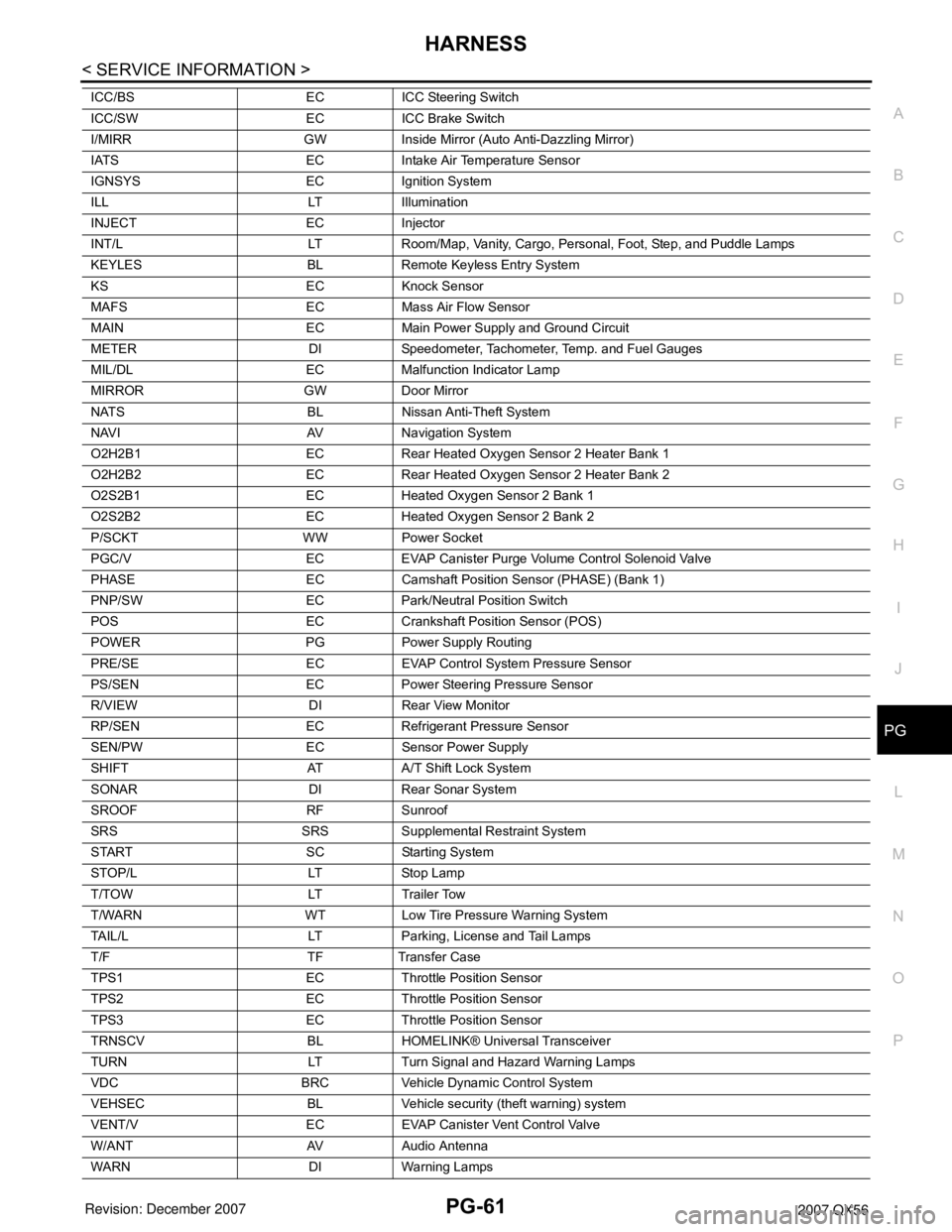
ICC/BS EC ICC Steering Switch
ICC/SW EC ICC Brake Switch
I/MIRR GW Inside Mirror (Auto Anti-Dazzling Mirror)
IATS EC Intake Air Temperature Sensor
IGNSYS EC Ignition System
ILL LT Illumination
INJECT EC Injector
INT/L LT Room/Map, Vanity, Cargo, Personal, Foot, Step, and Puddle Lamps
KEYLES BL Remote Keyless Entry System
KS EC Knock Sensor
MAFS EC Mass Air Flow Sensor
MAIN EC Main Power Supply and Ground Circuit
METER DI Speedometer, Tachometer, Temp. and Fuel Gauges
MIL/DL EC Malfunction Indicator Lamp
MIRROR GW Door Mirror
NATS BL Nissan Anti-Theft System
NAVI AV Navigation System
O2H2B1 EC Rear Heated Oxygen Sensor 2 Heater Bank 1
O2H2B2 EC Rear Heated Oxygen Sensor 2 Heater Bank 2
O2S2B1 EC Heated Oxygen Sensor 2 Bank 1
O2S2B2 EC Heated Oxygen Sensor 2 Bank 2
P/SCKT WW Power Socket
PGC/V EC EVAP Canister Purge Volume Control Solenoid Valve
PHASE EC Camshaft Position Sensor (PHASE) (Bank 1)
PNP/SW EC Park/Neutral Position Switch
POS EC Crankshaft Position Sensor (POS)
POWER PG Power Supply Routing
PRE/SE EC EVAP Control System Pressure Sensor
PS/SEN EC Power Steering Pressure Sensor
R/VIEW DI Rear View Monitor
RP/SEN EC Refrigerant Pressure Sensor
SEN/PW EC Sensor Power Supply
SHIFT AT A/T Shift Lock System
SONAR DI Rear Sonar System
SROOF RF Sunroof
SRS SRS Supplemental Restraint System
START SC Starting System
STOP/L LT Stop Lamp
T/TOW LT Trailer Tow
T/WARN WT Low Tire Pressure Warning System
TAIL/L LT Parking, License and Tail Lamps
T/F TF Transfer Case
TPS1 EC Throttle Position Sensor
TPS2 EC Throttle Position Sensor
TPS3 EC Throttle Position Sensor
TRNSCV BL HOMELINK® Universal Transceiver
TURN LT Turn Signal and Hazard Warning Lamps
VDC BRC Vehicle Dynamic Control System
VEHSEC BL Vehicle security (theft warning) system
VENT/V EC EVAP Canister Vent Control Valve
W/ANT AV Audio Antenna
WARN DI Warning Lamps
Page 2493 of 3061
PS-2
< SERVICE INFORMATION >
PRECAUTIONS
SERVICE INFORMATION
PRECAUTIONS
Precaution for Supplemental Restraint System (SRS) "AIR BAG" and "SEAT BELT
PRE-TENSIONER"
INFOID:0000000003532816
The Supplemental Restraint System such as “AIR BAG” and “SEAT BELT PRE-TENSIONER”, used along
with a front seat belt, helps to reduce the risk or severity of injury to the driver and front passenger for certain
types of collision. This system includes seat belt switch inputs and dual stage front air bag modules. The SRS
system uses the seat belt switches to determine the front air bag deployment, and may only deploy one front
air bag, depending on the severity of a collision and whether the front occupants are belted or unbelted.
Information necessary to service the system safely is included in the SRS and SB section of this Service Man-
ual.
WARNING:
• To avoid rendering the SRS inoperative, which could increase the risk of personal injury or death in
the event of a collision which would result in air bag inflation, all maintenance must be performed by
an authorized NISSAN/INFINITI dealer.
• Improper maintenance, including incorrect removal and installation of the SRS, can lead to personal
injury caused by unintentional activation of the system. For removal of Spiral Cable and Air Bag
Module, see the SRS section.
• Do not use electrical test equipment on any circuit related to the SRS unless instructed to in this
Service Manual. SRS wiring harnesses can be identified by yellow and/or orange harnesses or har-
ness connectors.
Precaution for Steering SystemINFOID:0000000003532817
• Before disassembly, thoroughly clean the outside of the unit.
• Disassembly should be done in a clean work area. It is important to prevent the internal parts from becoming
contaminated by dirt or other foreign matter.
• For easier and proper assembly, place disassembled parts in order on a parts rack.
• Use nylon cloth or paper towels to clean the parts; common shop rags can leave lint that might interfere with
their operation.
• Before inspection or reassembly, carefully clean all parts with a general purpose, non-flammable solvent.
• Before assembly, apply a coat of recommended Genuine NISSAN PSF or equivalent to hydraulic parts.
Petroleum jelly may be applied to O-rings and seals. Do not use any grease.
• Replace all gaskets, seals and O-rings. Avoid damaging O-rings, seals and gaskets during installation. Per-
form functional tests whenever designated.
Page 2527 of 3061
REAR DRIVE SHAFT
RAX-9
< SERVICE INFORMATION >
C
E
F
G
H
I
J
K
L
MA
B
RAX
N
O
P
When mounting the drive shaft in a vise, use copper or aluminum plates between the vise and the
drive shaft.
2. Remove the boot bands.
3. If the plug needs to be removed, move the boot to the wheel side, then drive the plug out using a suitable
plastic hammer.
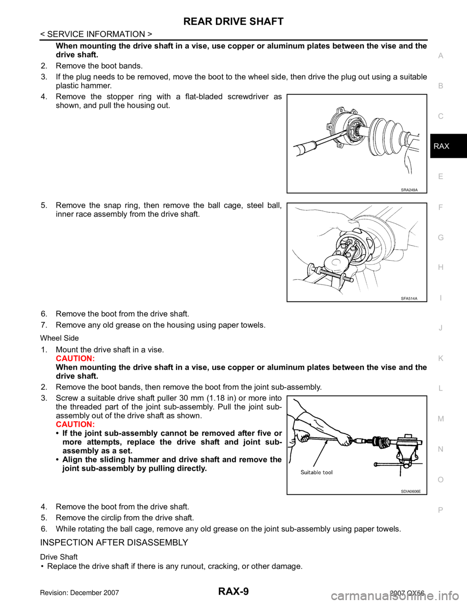
4. Remove the stopper ring with a flat-bladed screwdriver as
shown, and pull the housing out.
5. Remove the snap ring, then remove the ball cage, steel ball,
inner race assembly from the drive shaft.
6. Remove the boot from the drive shaft.
7. Remove any old grease on the housing using paper towels.
Wheel Side
1. Mount the drive shaft in a vise.
CAUTION:
When mounting the drive shaft in a vise, use copper or aluminum plates between the vise and the
drive shaft.
2. Remove the boot bands, then remove the boot from the joint sub-assembly.
3. Screw a suitable drive shaft puller 30 mm (1.18 in) or more into
the threaded part of the joint sub-assembly. Pull the joint sub-
assembly out of the drive shaft as shown.
CAUTION:
• If the joint sub-assembly cannot be removed after five or
more attempts, replace the drive shaft and joint sub-
assembly as a set.
• Align the sliding hammer and drive shaft and remove the
joint sub-assembly by pulling directly.
4. Remove the boot from the drive shaft.
5. Remove the circlip from the drive shaft.
6. While rotating the ball cage, remove any old grease on the joint sub-assembly using paper towels.
INSPECTION AFTER DISASSEMBLY
Drive Shaft
• Replace the drive shaft if there is any runout, cracking, or other damage.
SRA249A
SFA514A
SDIA0606E
Page 2619 of 3061
REAR SUSPENSION MEMBER
RSU-29
< SERVICE INFORMATION >
C
D
F
G
H
I
J
K
L
MA
B
RSU
N
O
P
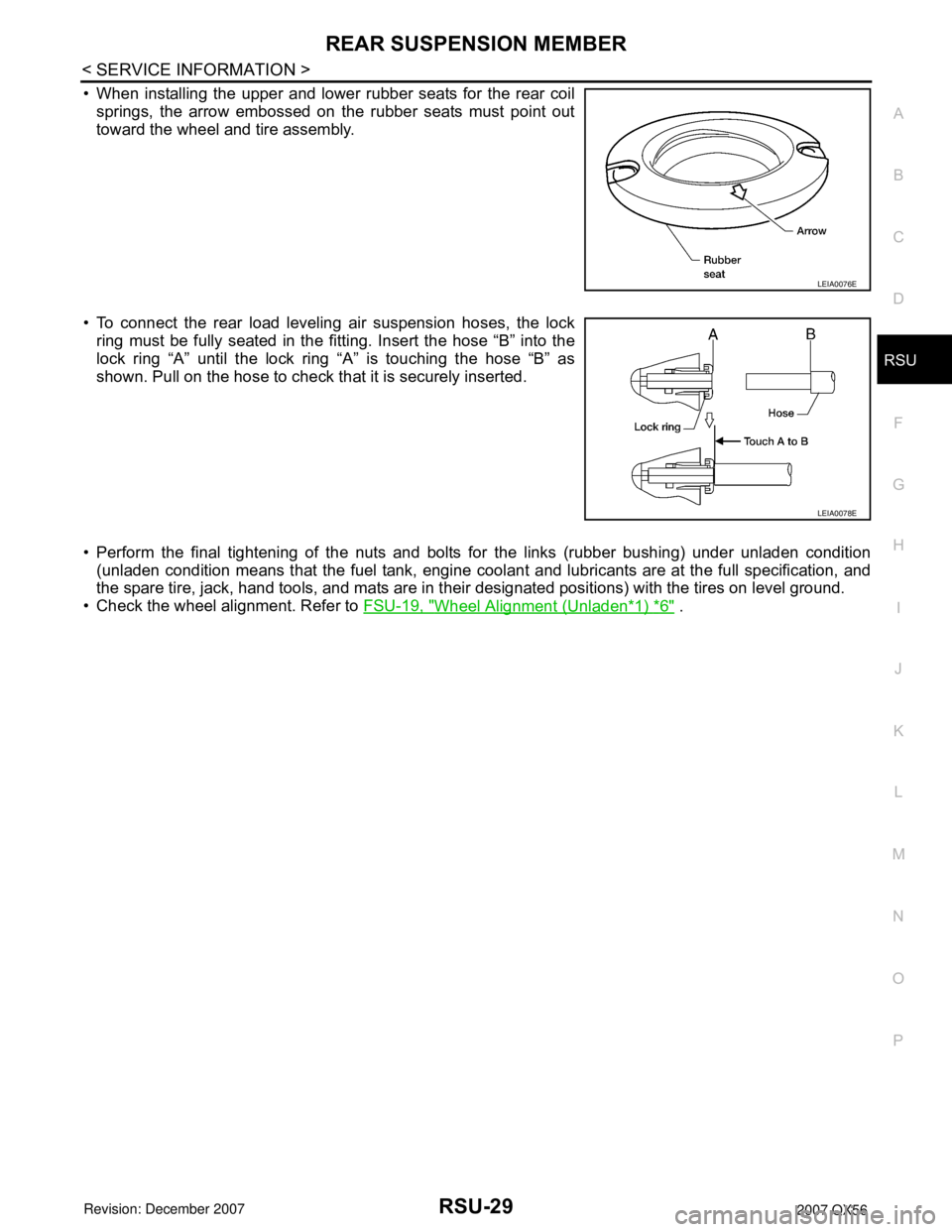
• When installing the upper and lower rubber seats for the rear coil
springs, the arrow embossed on the rubber seats must point out
toward the wheel and tire assembly.
• To connect the rear load leveling air suspension hoses, the lock
ring must be fully seated in the fitting. Insert the hose “B” into the
lock ring “A” until the lock ring “A” is touching the hose “B” as
shown. Pull on the hose to check that it is securely inserted.
• Perform the final tightening of the nuts and bolts for the links (rubber bushing) under unladen condition
(unladen condition means that the fuel tank, engine coolant and lubricants are at the full specification, and
the spare tire, jack, hand tools, and mats are in their designated positions) with the tires on level ground.
• Check the wheel alignment. Refer to FSU-19, "
Wheel Alignment (Unladen*1) *6" .
LEIA0076E
LEIA0078E