2007 INFINITI QX56 tow
[x] Cancel search: towPage 2078 of 3061

FRONT DOOR GLASS AND REGULATOR
GW-59
< SERVICE INFORMATION >
C
D
E
F
G
H
J
K
L
MA
B
GW
N
O
P
FRONT DOOR GLASS AND REGULATOR
Removal and InstallationINFOID:0000000003533061
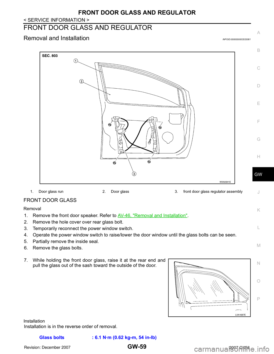
FRONT DOOR GLASS
Removal
1. Remove the front door speaker. Refer to AV-46, "Removal and Installation".
2. Remove the hole cover over rear glass bolt.
3. Temporarily reconnect the power window switch.
4. Operate the power window switch to raise/lower the door window until the glass bolts can be seen.
5. Partially remove the inside seal.
6. Remove the glass bolts.
7. While holding the front door glass, raise it at the rear end and
pull the glass out of the sash toward the outside of the door.
Installation
Installation is in the reverse order of removal.
1. Door glass run 2. Door glass 3. front door glass regulator assembly
WIIA0941E
LIIA1687E
Glass bolts : 6.1 N·m (0.62 kg-m, 54 in-lb)
Page 2112 of 3061

IDX-8
ALPHABETICAL INDEX
Three way catalyst ............................................ EM-21
Three way catalyst function (Bank 1) ............... EC-376
Three way catalyst function (Bank 2) ............... EC-376
Three way catalyst precautions ............................ GI-5
Throttle control motor ....................................... EC-601
Throttle control motor relay .............................. EC-589
Throttle position sensor (TPS) .. EC-224, EC-343, EC-
514, EC-516, EC-621
Throttle valve closed position learning ............... EC-80
Tie-rod ............................................................... PS-15
Timing chain ..................................................... EM-37
Tire rotation ....................................................... MA-28
Tire size .............................................................. GI-51
Torque converter installation AT-239, AT-240, AT-243,
AT-244
Torque convertor clutch solenoid valve ... AT-114, AT-
116
Tow truck towing ................................................. GI-44
Towing point ....................................................... GI-45
TPS1 - Wiring diagram .................................... EC-345
TPS2 - Wiring diagram .................................... EC-226
TPS3 - Wiring diagram .................................... EC-623
Traction control system - Wiring diagram ....... BRC-16
Transfer control device ............. TF-75, TF-79, TF-138
Transfer control unit inspection table ................. TF-35
Transfer dropping resistor .................................. TF-89
Transfer fluid temperature sensor TF-103, TF-154, TF-
167
Transfer motor .................................... TF-101, TF-142
Transfer motor relay ........................................ TF-101
Transfer oil replacement ................................... MA-24
Transfer serial number ........................................ GI-50
Transmission serial number ................................ GI-50
Tread-FR&RR (Dimensions) ............................... GI-51
Trim ..................................................................... EI-35
TRNSCV - Wiring diagram .................. BL-130, BL-146
Trouble diagnoses .............................................. GI-11
Turbine revolution sensor ................................ AT-105
TURN - Wiring diagram ...................................... LT-67
Turn signal lamp ................................................. LT-63
Two trip detection logic ...................................... EC-49
Two-pole lift ........................................................ GI-43
V
Vacuum hose (brake system) ............................ BR-20
Vacuum hose drawing (Engine control) ........... EC-106
Valve clearance ................................................ EM-55
Valve guide ....................................................... EM-69
Vanity mirror lamp ............................................. LT-110
VDC (vehicle dynamics control) ........................ BRC-7
VDC -Wiring diagram ...................................... BRC-16
Vehicle identification number .............................. GI-49
Vehicle recovery (freeing a stuck vehicle) .......... GI-45
Vehicle security (theft warning) system ............. BL-67
Vehicle speed sensor (VSS) ............................ EC-464
VEHSEC - Wiring diagram ................................. BL-71
VENT/V - Wiring diagram .................. EC-412, EC-419
VIN registration .................................................. EC-79
Viscosity number (SAE) .................................... MA-12
VSS A/T - Wiring diagram .................. AT-107, AT-109
W
W/ANT - Wiring diagram .................................... AV-59
Wait detection switch ......................................... TF-68
WARN - Wiring diagram ...................................... DI-29
Warning chime .................................................... DI-38
Warning lamps .................................................... DI-28
Washer, front ..................................................... WW-4
Washer, rear .................................................... WW-29
Water pump ...................................................... CO-19
Water temperature gauge ..................................... DI-5
Wheel alignment (front) ..................................... FSU-6
Wheel alignment (rear) ................................... RSU-25
Wheel bearing (front) ........................................ FAX-5
Wheel bearing (rear) ......................................... RAX-5
Wheel hub (rear) ............................................... RAX-5
Wheel size .......................................................... GI-51
Wheelbase (Dimensions) .................................... GI-51
Width (Dimensions) ............................................. GI-51
WINDOW - Wiring diagram .............................. GW-22
Window, door ...................................... GW-62, GW-65
Windshield ....................................................... GW-11
WIP/R - Wiring diagram ................................... WW-33
WIPER - Wiring diagram .................................... WW-8
Wiper, front ........................................................ WW-4
Wiper, rear ....................................................... WW-29
Wiring Diagram (Cell code) list ......................... PG-62
Wiring diagrams .................................................. GI-15
WT-T/WARN - Wiring diagram .......................... WT-11
Page 2177 of 3061
![INFINITI QX56 2007 Factory Service Manual LAN-46
< SERVICE INFORMATION >[CAN]
TROUBLE DIAGNOSIS
NOTE:
CAN data of the air bag diagnosis sensor unit is not used by usual service work, thus it is omitted.
TYPE 3/TYPE 4
NOTE:
Refer to LAN-37, " INFINITI QX56 2007 Factory Service Manual LAN-46
< SERVICE INFORMATION >[CAN]
TROUBLE DIAGNOSIS
NOTE:
CAN data of the air bag diagnosis sensor unit is not used by usual service work, thus it is omitted.
TYPE 3/TYPE 4
NOTE:
Refer to LAN-37, "](/manual-img/42/57029/w960_57029-2176.png)
LAN-46
< SERVICE INFORMATION >[CAN]
TROUBLE DIAGNOSIS
NOTE:
CAN data of the air bag diagnosis sensor unit is not used by usual service work, thus it is omitted.
TYPE 3/TYPE 4
NOTE:
Refer to LAN-37, "
Abbreviation List" for the abbreviations of the connecting units.
T: Transmit R: Receive
A/C switch/indicator signalTR
RT
1st position switch signal R T
4th position switch signal R T
Distance to empty signal R T
Fuel level low warning signal R T
Fuel level sensor signal R T
Parking brake switch signal R T
Stop lamp switch signal R T
Tow mode switch signal R T
Vehicle speed signalRR T
RRR RRR T
Steering angle sensor signalTR
ABS malfunction signal R T
ABS warning lamp signalRT
Brake pressure sensor signal R T
Brake warning lamp signalRT
SLIP indicator lamp signalRT
TCS malfunction signal R T
VDC malfunction signal R T
VDC OFF indicator lamp signal R R T
VDC operation signal R T
Front wiper stop position signal R T
High beam status signal RT
Hood switch signal R T
Low beam status signal RT
Rear window defogger control signal R R TSignal name/Connecting unit
ECM
TCM
LASER
ICC
ADP
BCM
DISP
HVAC
M&A
STRG
ABS
IPDM-E
Signal name/Connecting unitECM
TCM
LASER
ICC
ADP
BCM
DISP
HVAC
M&A
STRG
4WD
ABS
IPDM-E
A/C compressor request signal TR
Accelerator pedal position signal T R R R R
ASCD CRUISE lamp signal T R
ASCD OD cancel request signal T R
ASCD operation signal T R
ASCD SET lamp signal T R
Battery voltage signal T R
Closed throttle position signal T R R
Page 2179 of 3061
![INFINITI QX56 2007 Factory Service Manual LAN-48
< SERVICE INFORMATION >[CAN]
TROUBLE DIAGNOSIS
NOTE:
CAN data of the air bag diagnosis sensor unit is not used by usual service work, thus it is omitted.
Tire pressure signal T R R
Turn indica INFINITI QX56 2007 Factory Service Manual LAN-48
< SERVICE INFORMATION >[CAN]
TROUBLE DIAGNOSIS
NOTE:
CAN data of the air bag diagnosis sensor unit is not used by usual service work, thus it is omitted.
Tire pressure signal T R R
Turn indica](/manual-img/42/57029/w960_57029-2178.png)
LAN-48
< SERVICE INFORMATION >[CAN]
TROUBLE DIAGNOSIS
NOTE:
CAN data of the air bag diagnosis sensor unit is not used by usual service work, thus it is omitted.
Tire pressure signal T R R
Turn indicator signal T R
A/C switch/indicator signalTR
RT
1st position switch signal R T
4th position switch signal R T
Distance to empty signal R T
Fuel level low warning signal R T
Fuel level sensor signal R T
Parking brake switch signal R T
Stop lamp switch signal R T
Tow mode switch signal R T
Vehicle speed signalRR R T
RRR RRR T
Steering angle sensor signalTR
ABS malfunction signal R T
ABS warning lamp signalRT
Brake pressure sensor signal R T
Brake warning lamp signalRT
SLIP indicator lamp signalRT
TCS malfunction signal R T
VDC malfunction signal R T
VDC OFF indicator lamp signal R R T
VDC operation signal R T
Front wiper stop position signal R T
High beam status signal RT
Hood switch signal R T
Low beam status signal RT
Rear window defogger control signal R R TSignal name/Connecting unit
ECM
TCM
LASER
ICC
ADP
BCM
DISP
HVAC
M&A
STRG
4WD
ABS
IPDM-E
Page 2209 of 3061

LT-2
Wiring Diagram - F/FOG - ......................................51
Terminal and Reference Value for BCM .................52
Terminal and Reference Value for IPDM E/R .........52
How to Proceed with Trouble Diagnosis .................53
Preliminary Check ..................................................53
CONSULT-II Function for BCM ..............................53
CONSULT-II Function for IPDM E/R ......................53
Front Fog Lamps Do Not Illuminate (Both Sides) ...53
Front Fog Lamp Does Not Illuminate (One Side) ...54
Aiming Adjustment ..................................................55
Bulb Replacement ..................................................55
Removal and Installation ........................................56
TURN SIGNAL AND HAZARD WARNING
LAMPS ...............................................................
57
Component Parts and Harness Connector Loca-
tion ..........................................................................
57
System Description .................................................57
CAN Communication System Description ..............59
Schematic ...............................................................60
Wiring Diagram - TURN - ........................................61
Terminal and Reference Value for BCM .................63
How to Proceed with Trouble Diagnosis .................63
Preliminary Check ..................................................64
CONSULT-II Function (BCM) .................................64
Front Turn Signal Lamp Does Not Operate ............64
Door Mirror Turn Signal Lamp Does Not Operate ...65
Rear Turn Signal Lamp Does Not Operate ............66
Hazard Warning Lamp Does Not Operate But
Turn Signal Lamp Operatess ..................................
67
Turn Signal Indicator Lamp Does Not Operate ......68
Bulb Replacement ..................................................69
Removal and Installation ........................................69
LIGHTING AND TURN SIGNAL SWITCH .........70
Removal and Installation ........................................70
HAZARD SWITCH .............................................71
Removal and Installation ........................................71
COMBINATION SWITCH ..................................72
Wiring Diagram - COMBSW - .................................72
Combination Switch Reading Function ...................72
CONSULT-II Function (BCM) .................................73
Combination Switch Inspection ..............................73
Removal and Installation ........................................76
Switch Circuit Inspection ........................................76
STOP LAMP ......................................................77
System Description .................................................77
Wiring Diagram - STOP/L - .....................................78
Bulb Replacement ..................................................78
Removal and Installation ........................................79
BACK-UP LAMP ................................................80
Wiring Diagram - BACK/L - .....................................80
Bulb Replacement ..................................................80
Removal and Installation ........................................81
PARKING, LICENSE PLATE AND TAIL
LAMPS ...............................................................
82
Component Parts and Harness Connector Loca-
tion ..........................................................................
82
System Description .................................................82
CAN Communication System Description ..............83
Schematic ...............................................................84
Wiring Diagram - TAIL/L - .......................................85
Terminal and Reference Value for BCM .................87
Terminal and Reference Value for IPDM E/R .........87
How to Proceed with Trouble Diagnosis .................88
Preliminary Check ...................................................88
CONSULT-II Function for BCM ...............................88
CONSULT-II Function for IPDM E/R .......................88
Parking, License Plate and/or Tail Lamps Do Not
Illuminate .................................................................
88
Parking, License Plate and Tail Lamps Do Not
Turn OFF (After Approx. 10 Minutes) .....................
91
Bulb Replacement ...................................................91
Removal and Installation .........................................92
REAR COMBINATION LAMP ...........................93
Bulb Replacement ...................................................93
Removal and Installation .........................................93
TRAILER TOW ..................................................94
Component Parts and Harness Connector Loca-
tion ..........................................................................
94
System Description .................................................94
Schematic ...............................................................96
Wiring Diagram - T/TOW - ......................................97
INTERIOR ROOM LAMP ..................................101
Component Parts and Harness Connector Loca-
tion ........................................................................
101
System Description ...............................................101
Schematic .............................................................105
Wiring Diagram - INT/L - .......................................107
Terminal and Reference Value for BCM ...............113
How to Proceed with Trouble Diagnosis ...............113
Preliminary Check .................................................114
CONSULT-II Function (BCM) ...............................114
Room/Map Lamp Control Does Not Operate ........115
Personal Lamp Control Does Not Operate (Room/
Map Lamps Operate) ............................................
116
All Step/Foot/Puddle Lamps Do Not Operate .......117
All Interior Room Lamps Do Not Operate .............118
Ignition Keyhole Illumination Control Does Not
Operate .................................................................
118
ILLUMINATION ................................................120
Component Parts and Harness Connector Loca-
tion ........................................................................
120
System Description ...............................................120
CAN Communication System Description ............122
Schematic .............................................................123
Wiring Diagram - ILL - ...........................................126
Removal and Installation of Illumination Control
Switch ...................................................................
136
Page 2213 of 3061

LT-6
< SERVICE INFORMATION >
HEADLAMP (FOR USA)
• to BCM terminal 38.
Ground is supplied
• to BCM terminal 67
• through grounds M57, M61 and M79, and
• to IPDM E/R terminals 38 and 59
• through grounds E9, E15 and E24.
Low Beam Operation
With the lighting switch in 2ND position, the BCM receives input requesting the headlamps to illuminate. This
input is communicated to the IPDM E/R across the CAN communication lines. The CPU of the IPDM E/R con-
trols the headlamp low relay coil. When energized, this relay directs power
• through 15A fuse (No. 41, located in the IPDM E/R)
• through IPDM E/R terminal 54
• to front combination lamp RH terminal 5, and
• through 15A fuse (No. 40, located in the IPDM E/R)
• through IPDM E/R terminal 52
• to front combination lamp LH terminal 5.
Ground is supplied
• to front combination lamp LH and RH terminal 1
• through grounds E9, E15 and E24.
With power and ground supplied, low beam headlamps illuminate.
High Beam Operation/Flash-to-Pass Operation
With the lighting switch in 2ND position and placed in HIGH or PASS position, the BCM receives input request-
ing the headlamp high beams to illuminate. This input is communicated to the IPDM E/R across the CAN com-
munication lines. The CPU of the combination meter controls the ON/OFF status of the HIGH BEAM indicator.
The CPU of the IPDM E/R controls the headlamp high relay coil. When energized, this relay directs power
• through 10A fuse (No. 34, located in the IPDM E/R)
• through IPDM E/R terminal 56
• to front combination lamp RH terminal 6, and
• through 10A fuse (No. 35, located in the IPDM E/R)
• through IPDM E/R terminal 55
• to front combination lamp LH terminal 6.
Ground is supplied
• to front combination lamp LH and RH terminal 2
• through grounds E9, E15 and E24.
With power and ground supplied, the high beam headlamps illuminate.
XENON HEADLAMP
Xenon type headlamp is adopted to the low beam headlamps. Xenon bulbs do not use a filament. Instead,
they produce light when a high voltage current is passed between two tungsten electrodes through a mixture
of xenon (an inert gas) and certain other metal halides. In addition to added lighting power, electronic control
of the power supply gives the headlamps stable quality and tone color.
Following are some of the many advantages of the xenon type headlamp.
• The light produced by the headlamps is a white color comparable to sunlight that is easy on the eyes.
• Light output is nearly double that of halogen headlamps, affording increased area of illumination.
• The light features a high relative spectral distribution at wavelengths to which the human eye is most sensi-
tive. This means that even in the rain, more light is reflected back from the road surface toward the vehicle,
for added visibility.
• Power consumption is approximately 25 percent less than halogen headlamps, reducing battery load.
BATTERY SAVER CONTROL
When the combination switch (lighting switch) is in the 2ND position (ON), and the ignition switch is turned
from ON or ACC to OFF, the battery saver control feature is activated.
Under this condition, the headlamps remain illuminated for 5 minutes, unless the combination switch (lighting
switch) position is changed. If the combination switch (lighting switch) position is changed, then the headlamps
are turned off.
AUTO LIGHT OPERATION
Refer to LT-34, "System Description" for auto light operation.
VEHICLE SECURITY SYSTEM (PANIC ALARM)
Page 2228 of 3061

HEADLAMP (FOR USA)
LT-21
< SERVICE INFORMATION >
C
D
E
F
G
H
I
J
L
MA
B
LT
N
O
P
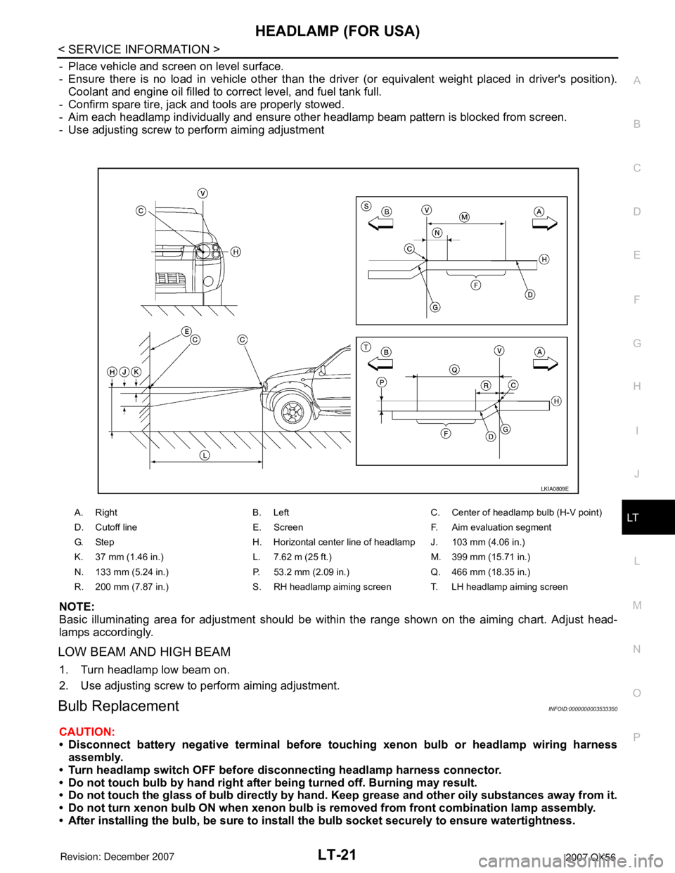
- Place vehicle and screen on level surface.
- Ensure there is no load in vehicle other than the driver (or equivalent weight placed in driver's position).
Coolant and engine oil filled to correct level, and fuel tank full.
- Confirm spare tire, jack and tools are properly stowed.
- Aim each headlamp individually and ensure other headlamp beam pattern is blocked from screen.
- Use adjusting screw to perform aiming adjustment
NOTE:
Basic illuminating area for adjustment should be within the range shown on the aiming chart. Adjust head-
lamps accordingly.
LOW BEAM AND HIGH BEAM
1. Turn headlamp low beam on.
2. Use adjusting screw to perform aiming adjustment.
Bulb ReplacementINFOID:0000000003533350
CAUTION:
• Disconnect battery negative terminal before touching xenon bulb or headlamp wiring harness
assembly.
• Turn headlamp switch OFF before disconnecting headlamp harness connector.
• Do not touch bulb by hand right after being turned off. Burning may result.
• Do not touch the glass of bulb directly by hand. Keep grease and other oily substances away from it.
• Do not turn xenon bulb ON when xenon bulb is removed from front combination lamp assembly.
• After installing the bulb, be sure to install the bulb socket securely to ensure watertightness.
A. Right B. Left C. Center of headlamp bulb (H-V point)
D. Cutoff line E. Screen F. Aim evaluation segment
G. Step H. Horizontal center line of headlamp J. 103 mm (4.06 in.)
K. 37 mm (1.46 in.) L. 7.62 m (25 ft.) M. 399 mm (15.71 in.)
N. 133 mm (5.24 in.) P. 53.2 mm (2.09 in.) Q. 466 mm (18.35 in.)
R. 200 mm (7.87 in.) S. RH headlamp aiming screen T. LH headlamp aiming screen
LKIA0809E
Page 2277 of 3061

LT-70
< SERVICE INFORMATION >
LIGHTING AND TURN SIGNAL SWITCH
LIGHTING AND TURN SIGNAL SWITCH
Removal and InstallationINFOID:0000000003533419
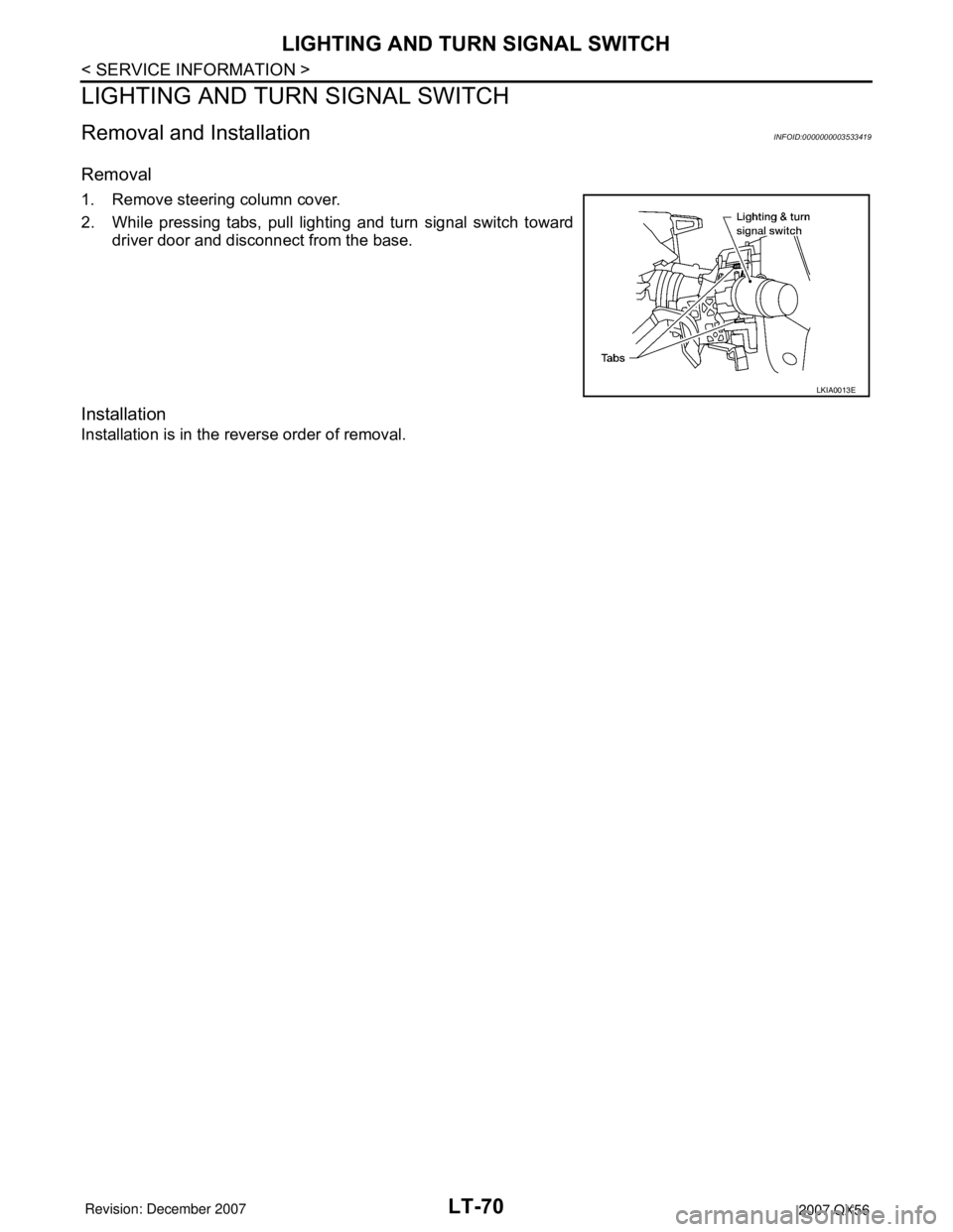
Removal
1. Remove steering column cover.
2. While pressing tabs, pull lighting and turn signal switch toward
driver door and disconnect from the base.
Installation
Installation is in the reverse order of removal.
LKIA0013E