Page 2626 of 3061
RSU-36
< SERVICE INFORMATION >
REAR LOWER LINK & COIL SPRING
8. Remove the rear lower link adjusting bolt and nut from the rear
suspension member using power tool, then remove the rear
lower link.
INSPECTION AFTER REMOVAL
Check the coil spring and rubber seats for deformation, cracks, or other damage and replace if necessary.
INSTALLATION
Installation is in the reverse order of removal.
• Tighten the nuts and bolts to specification. Refer to RSU-21, "
Component" .
• When installing the upper and lower rubber seats for the rear coil
springs, the arrow embossed on the rubber seats must point out
toward the wheel and tire assembly.
• After installing the rear lower link and coil spring, check the wheel
alignment and adjust if necessary. Refer to RSU-23, "
Wheel Align-
mentInspection"
LEIA0009E
LEIA0076E
Page 2772 of 3061

SRS-2
< SERVICE INFORMATION >
PRECAUTIONS
SERVICE INFORMATION
PRECAUTIONS
Precaution for Supplemental Restraint System (SRS) "AIR BAG" and "SEAT BELT
PRE-TENSIONER"
INFOID:0000000003532849
The Supplemental Restraint System such as “AIR BAG” and “SEAT BELT PRE-TENSIONER”, used along
with a front seat belt, helps to reduce the risk or severity of injury to the driver and front passenger for certain
types of collision. This system includes seat belt switch inputs and dual stage front air bag modules. The SRS
system uses the seat belt switches to determine the front air bag deployment, and may only deploy one front
air bag, depending on the severity of a collision and whether the front occupants are belted or unbelted.
Information necessary to service the system safely is included in the SRS and SB section of this Service Man-
ual.
WARNING:
• To avoid rendering the SRS inoperative, which could increase the risk of personal injury or death in
the event of a collision which would result in air bag inflation, all maintenance must be performed by
an authorized NISSAN/INFINITI dealer.
• Improper maintenance, including incorrect removal and installation of the SRS, can lead to personal
injury caused by unintentional activation of the system. For removal of Spiral Cable and Air Bag
Module, see the SRS section.
• Do not use electrical test equipment on any circuit related to the SRS unless instructed to in this
Service Manual. SRS wiring harnesses can be identified by yellow and/or orange harnesses or har-
ness connectors.
Precaution for SRS "AIR BAG" and "SEAT BELT PRE-TENSIONER" Service
INFOID:0000000003532850
• Do not use electrical test equipment to check SRS circuits unless instructed to in this Service Manual.
• Before servicing the SRS, turn ignition switch OFF, disconnect both battery cables and wait at least 3 min-
utes.
For approximately 3 minutes after the cables are removed, it is still possible for the air bags and seat belt
pre-tensioners to deploy. Therefore, do not work on any SRS connectors or wires until at least 3 minutes
have passed.
• The air diagnosis sensor unit must always be installed with the arrow mark “⇐” pointing toward the front of
the vehicle for proper operation. Also check air bag diagnosis sensor unit for cracks, deformities or rust
before installation and replace as required.
• The spiral cable must be aligned with the neutral position since its rotations are limited. Do not attempt to
turn steering wheel or column after removal of steering gear.
• Handle air bag module carefully. Always place driver and front passenger air bag modules with the pad side
facing upward and seat mounted front side air bag module standing with the stud bolt side facing down.
• Conduct self-diagnosis to check entire SRS for proper function after replacing any components.
• After air bag inflates, the front instrument panel assembly should be replaced if damaged.
Occupant Classification System PrecautionINFOID:0000000003532851
Replace control unit and passenger front seat cushion as an assembly.
Page 2807 of 3061
SPIRAL CABLE
SRS-37
< SERVICE INFORMATION >
C
D
E
F
G
I
J
K
L
MA
B
SRS
N
O
P
SPIRAL CABLE
Removal and InstallationINFOID:0000000003532874
REMOVAL
CAUTION:
• Before servicing the SRS, turn ignition switch OFF, disconnect both battery cables and wait at least
3 minutes.
• When servicing the SRS, do not work from directly in front of air bag module.
1. Remove the steering wheel. Refer to PS-7
.
2. Remove the column cover upper and lower.
3. Remove wiper and washer switch connector, then pinch the tabs
at wiper and washer switch base and slide away from steering
column to remove.
4. While pressing tabs, pull lighting and turn signal switch toward
driver door and disconnect from base.
WHIA0233E
1. Steering wheel 2. Lighting and turn signal switch 3. Wiper and washer switch
4. Spiral cable 5. Driver air bag module connector 6. Column cover upper
7. Column assembly 8. Column cover lower 9. Screw (Do not remove)
10. Screw
LHIA0034E
LHIA0035E
Page 2817 of 3061

DIAGNOSIS SENSOR UNIT
SRS-47
< SERVICE INFORMATION >
C
D
E
F
G
I
J
K
L
MA
B
SRS
N
O
P
DIAGNOSIS SENSOR UNIT
Removal and InstallationINFOID:0000000003532880
REMOVAL
CAUTION:
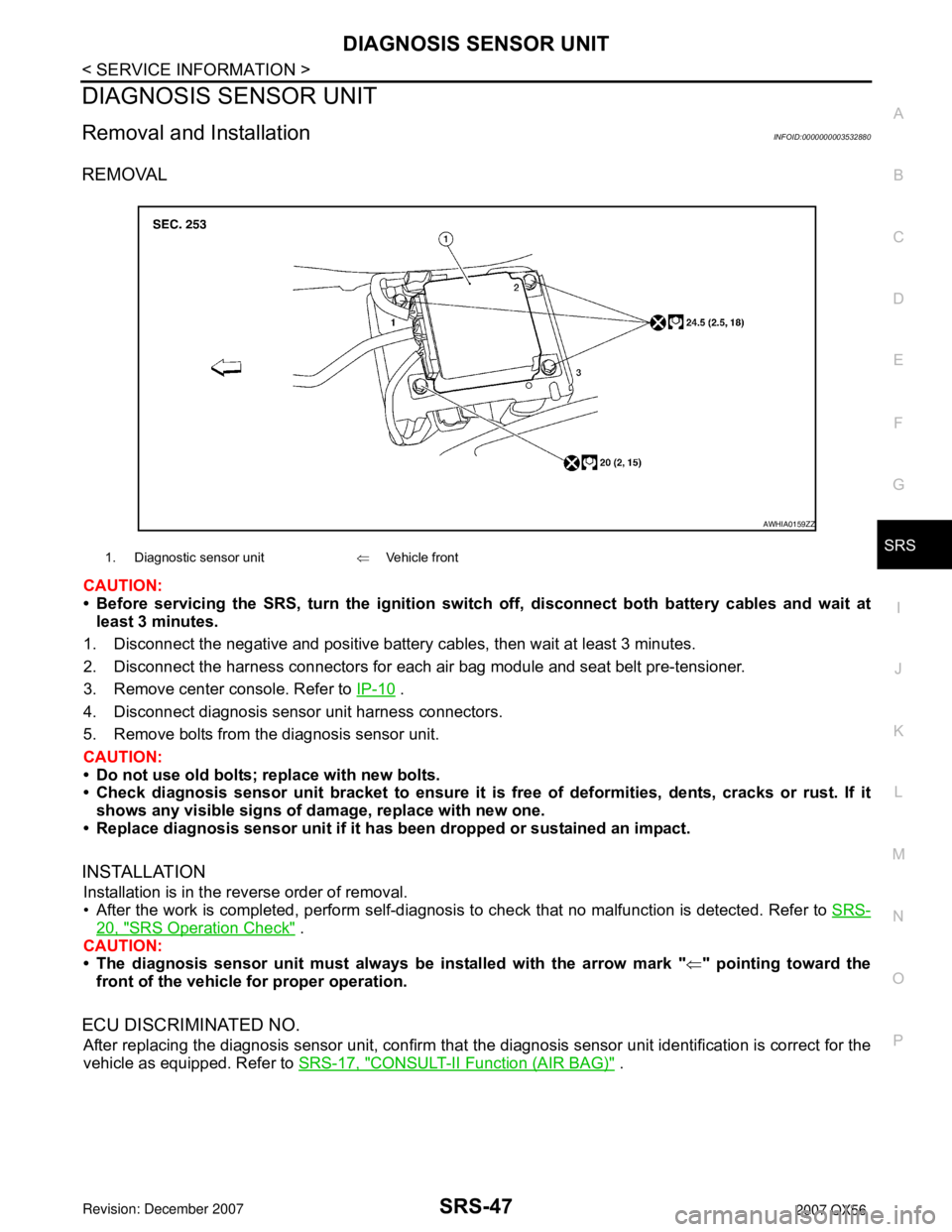
• Before servicing the SRS, turn the ignition switch off, disconnect both battery cables and wait at
least 3 minutes.
1. Disconnect the negative and positive battery cables, then wait at least 3 minutes.
2. Disconnect the harness connectors for each air bag module and seat belt pre-tensioner.
3. Remove center console. Refer to IP-10
.
4. Disconnect diagnosis sensor unit harness connectors.
5. Remove bolts from the diagnosis sensor unit.
CAUTION:
• Do not use old bolts; replace with new bolts.
• Check diagnosis sensor unit bracket to ensure it is free of deformities, dents, cracks or rust. If it
shows any visible signs of damage, replace with new one.
• Replace diagnosis sensor unit if it has been dropped or sustained an impact.
INSTALLATION
Installation is in the reverse order of removal.
• After the work is completed, perform self-diagnosis to check that no malfunction is detected. Refer to SRS-
20, "SRS Operation Check" .
CAUTION:
• The diagnosis sensor unit must always be installed with the arrow mark "⇐" pointing toward the
front of the vehicle for proper operation.
ECU DISCRIMINATED NO.
After replacing the diagnosis sensor unit, confirm that the diagnosis sensor unit identification is correct for the
vehicle as equipped. Refer to SRS-17, "
CONSULT-II Function (AIR BAG)" .
1. Diagnostic sensor unit⇐Vehicle front
AWHIA0159ZZ
Page 2827 of 3061
PRECAUTIONS
TF-5
< SERVICE INFORMATION >
C
E
F
G
H
I
J
K
L
MA
B
TF
N
O
P
• Use lint-free cloth or towels for wiping parts clean. Common shop rags can leave fibers that could interfere
with the operation of the transfer.
Page 3055 of 3061

WW-38
< SERVICE INFORMATION >
REAR WIPER AND WASHER SYSTEM
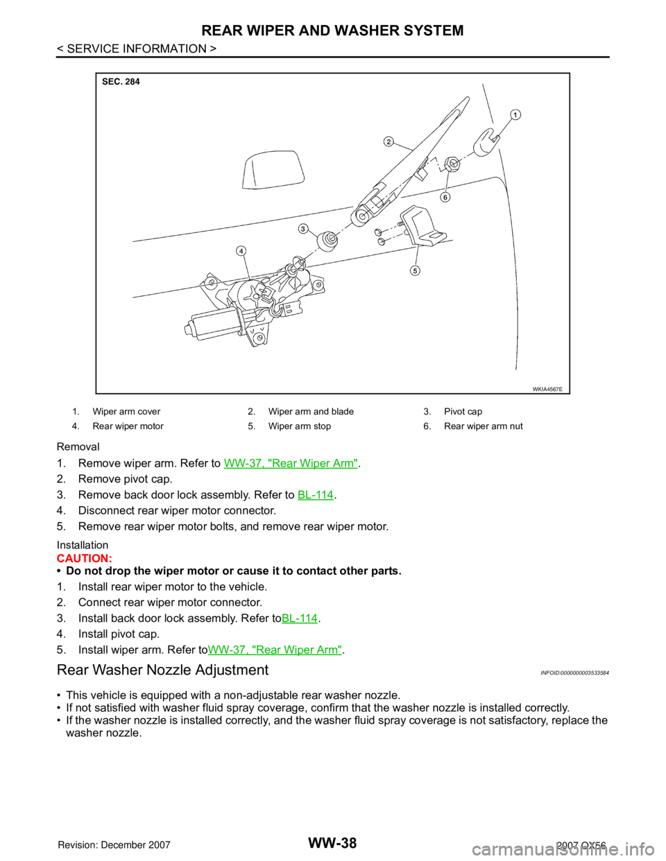
Removal
1. Remove wiper arm. Refer to WW-37, "Rear Wiper Arm".
2. Remove pivot cap.
3. Remove back door lock assembly. Refer to BL-114
.
4. Disconnect rear wiper motor connector.
5. Remove rear wiper motor bolts, and remove rear wiper motor.
Installation
CAUTION:
• Do not drop the wiper motor or cause it to contact other parts.
1. Install rear wiper motor to the vehicle.
2. Connect rear wiper motor connector.
3. Install back door lock assembly. Refer toBL-114
.
4. Install pivot cap.
5. Install wiper arm. Refer toWW-37, "
Rear Wiper Arm".
Rear Washer Nozzle AdjustmentINFOID:0000000003533584
• This vehicle is equipped with a non-adjustable rear washer nozzle.
• If not satisfied with washer fluid spray coverage, confirm that the washer nozzle is installed correctly.
• If the washer nozzle is installed correctly, and the washer fluid spray coverage is not satisfactory, replace the
washer nozzle.
WKIA4567E
1. Wiper arm cover 2. Wiper arm and blade 3. Pivot cap
4. Rear wiper motor 5. Wiper arm stop 6. Rear wiper arm nut
Page 3056 of 3061
REAR WIPER AND WASHER SYSTEM
WW-39
< SERVICE INFORMATION >
C
D
E
F
G
H
I
J
L
MA
B
WW
N
O
P
Rear Washer Tube LayoutINFOID:0000000003533585
NOTE:
Connect the check valve (2) to the washer fluid reservoir tube (1) so
that the directional arrow on the check valve (2) points towards the
washer nozzle tube (3).
Rear Washer NozzleINFOID:0000000003533586
REMOVAL AND INSTALLATION
Removal
1. Remove the rear spoiler. Refer to EI-25.
2. Release retaining clips, and remove washer nozzle.
Installation
Installation is in the reverse order of removal.
Rear Wiper and Washer SwitchINFOID:0000000003533587
REMOVAL AND INSTALLATION
Refer to IP-10, "Removal and Installation".
WKIA4566E
1. Rear washer nozzle 2. Washer fluid reservoir 3. Check valve
WKIA4242E
LKIA0418E