2007 INFINITI QX56 check engine light
[x] Cancel search: check engine lightPage 1459 of 3061
EC-376
< SERVICE INFORMATION >
DTC P0444, P0445 EVAP CANISTER PURGE VOLUME CONTROL SOLENOID
VALVE
Do not use ECM ground terminals when measuring input/output voltage. Doing so may result in dam-
age to the ECM's transistor. Use a ground other than ECM terminals, such as the ground.
: Average voltage for pulse signal (Actual pulse signal can be confirmed by oscilloscope.)
Diagnosis ProcedureINFOID:0000000003531872
1.CHECK EVAP CANISTER PURGE VOLUME CONTROL SOLENOID VALVE POWER SUPPLY CIRCUIT
1. Turn ignition switch OFF.
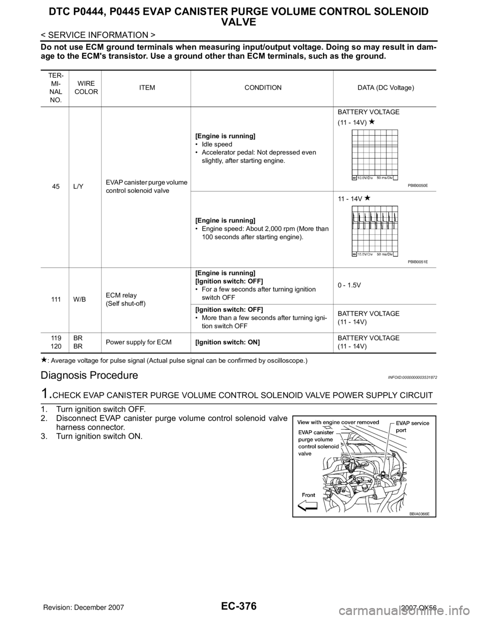
2. Disconnect EVAP canister purge volume control solenoid valve
harness connector.
3. Turn ignition switch ON.
TER-
MI-
NAL
NO.WIRE
COLORITEM CONDITION DATA (DC Voltage)
45 L/YEVAP canister purge volume
control solenoid valve[Engine is running]
• Idle speed
• Accelerator pedal: Not depressed even
slightly, after starting engine.BATTERY VOLTAGE
(11 - 14V)
[Engine is running]
• Engine speed: About 2,000 rpm (More than
100 seconds after starting engine).11 - 1 4 V
111 W / BECM relay
(Self shut-off)[Engine is running]
[Ignition switch: OFF]
• For a few seconds after turning ignition
switch OFF0 - 1.5V
[Ignition switch: OFF]
• More than a few seconds after turning igni-
tion switch OFFBATTERY VOLTAGE
(11 - 14V)
11 9
120BR
BRPower supply for ECM[Ignition switch: ON]BATTERY VOLTAGE
(11 - 14V)
PBIB0050E
PBIB0051E
BBIA0366E
Page 1476 of 3061
DTC P0451 EVAP CONTROL SYSTEM PRESSURE SENSOR
EC-393
< SERVICE INFORMATION >
C
D
E
F
G
H
I
J
K
L
MA
EC
N
P O
2. Turn ignition switch ON and select “DATA MONITOR” mode with
CONSULT-II.
3. Start engine and wait at least 40 seconds.
NOTE:
Do not depress accelerator pedal even slightly.
If 1st trip DTC is detected, go to EC-393, "
Diagnosis Procedure".
WITH GST
Follow the procedure “WITH CONSULT-II” above.
Diagnosis ProcedureINFOID:0000000003531893
1.CHECK GROUND CONNECTIONS
1. Turn ignition switch OFF.
2. Loosen and retighten three ground screws on the body.
Refer to EC-143, "
Ground Inspection".
OK or NG
OK >> GO TO 2.
NG >> Repair or replace ground connections.
2.CHECK EVAP CONTROL SYSTEM PRESSURE SENSOR CONNECTOR FOR WATER
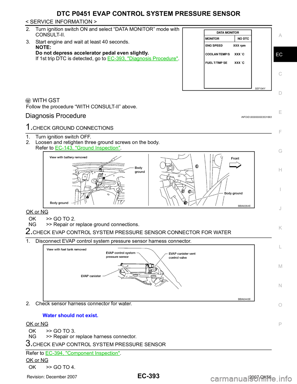
1. Disconnect EVAP control system pressure sensor harness connector.
2. Check sensor harness connector for water.
OK or NG
OK >> GO TO 3.
NG >> Repair or replace harness connector.
3.CHECK EVAP CONTROL SYSTEM PRESSURE SENSOR
Refer to EC-394, "
Component Inspection".
OK or NG
OK >> GO TO 4.
SEF194Y
BBIA0354E
Water should not exist.
BBIA0443E
Page 1584 of 3061
DTC P1554 BATTERY CURRENT SENSOR
EC-501
< SERVICE INFORMATION >
C
D
E
F
G
H
I
J
K
L
MA
EC
N
P O
DTC P1554 BATTERY CURRENT SENSOR
Component DescriptionINFOID:0000000003532032
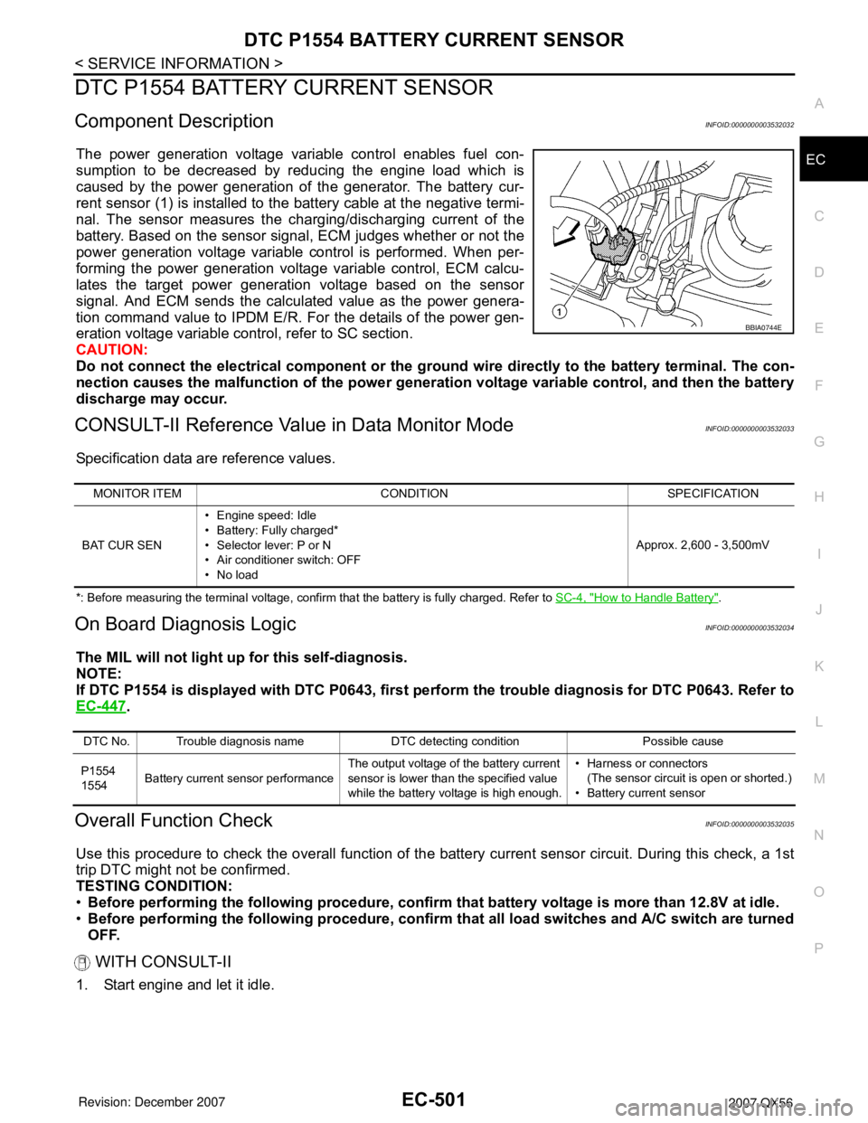
The power generation voltage variable control enables fuel con-
sumption to be decreased by reducing the engine load which is
caused by the power generation of the generator. The battery cur-
rent sensor (1) is installed to the battery cable at the negative termi-
nal. The sensor measures the charging/discharging current of the
battery. Based on the sensor signal, ECM judges whether or not the
power generation voltage variable control is performed. When per-
forming the power generation voltage variable control, ECM calcu-
lates the target power generation voltage based on the sensor
signal. And ECM sends the calculated value as the power genera-
tion command value to IPDM E/R. For the details of the power gen-
eration voltage variable control, refer to SC section.
CAUTION:
Do not connect the electrical component or the ground wire directly to the battery terminal. The con-
nection causes the malfunction of the power generation voltage variable control, and then the battery
discharge may occur.
CONSULT-II Reference Value in Data Monitor ModeINFOID:0000000003532033
Specification data are reference values.
*: Before measuring the terminal voltage, confirm that the battery is fully charged. Refer to SC-4, "How to Handle Battery".
On Board Diagnosis LogicINFOID:0000000003532034
The MIL will not light up for this self-diagnosis.
NOTE:
If DTC P1554 is displayed with DTC P0643, first perform the trouble diagnosis for DTC P0643. Refer to
EC-447
.
Overall Function CheckINFOID:0000000003532035
Use this procedure to check the overall function of the battery current sensor circuit. During this check, a 1st
trip DTC might not be confirmed.
TESTING CONDITION:
•Before performing the following procedure, confirm that battery voltage is more than 12.8V at idle.
•Before performing the following procedure, confirm that all load switches and A/C switch are turned
OFF.
WITH CONSULT-II
1. Start engine and let it idle.
BBIA0744E
MONITOR ITEM CONDITION SPECIFICATION
BAT CUR SEN• Engine speed: Idle
• Battery: Fully charged*
• Selector lever: P or N
• Air conditioner switch: OFF
•No loadApprox. 2,600 - 3,500mV
DTC No. Trouble diagnosis name DTC detecting condition Possible cause
P1554
1554Battery current sensor performanceThe output voltage of the battery current
sensor is lower than the specified value
while the battery voltage is high enough.• Harness or connectors
(The sensor circuit is open or shorted.)
• Battery current sensor
Page 1689 of 3061
EC-606
< SERVICE INFORMATION >
ELECTRICAL LOAD SIGNAL
ELECTRICAL LOAD SIGNAL
DescriptionINFOID:0000000003532157
The electrical load signal (Headlamp switch signal, rear window defogger switch signal, etc.) is transferred
through the CAN communication line from BCM to ECM via IPDM E/R.
CONSULT-II Reference Value in Data Monitor ModeINFOID:0000000003532158
Specification data are reference values.
Diagnosis ProcedureINFOID:0000000003532159
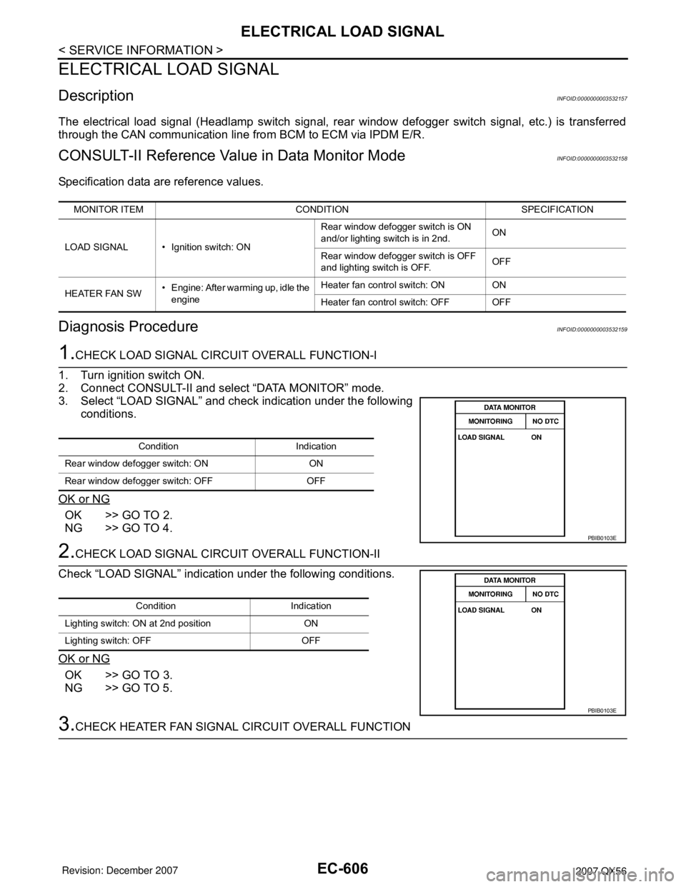
1.CHECK LOAD SIGNAL CIRCUIT OVERALL FUNCTION-I
1. Turn ignition switch ON.
2. Connect CONSULT-II and select “DATA MONITOR” mode.
3. Select “LOAD SIGNAL” and check indication under the following
conditions.
OK or NG
OK >> GO TO 2.
NG >> GO TO 4.
2.CHECK LOAD SIGNAL CIRCUIT OVERALL FUNCTION-II
Check “LOAD SIGNAL” indication under the following conditions.
OK or NG
OK >> GO TO 3.
NG >> GO TO 5.
3.CHECK HEATER FAN SIGNAL CIRCUIT OVERALL FUNCTION
MONITOR ITEM CONDITION SPECIFICATION
LOAD SIGNAL • Ignition switch: ONRear window defogger switch is ON
and/or lighting switch is in 2nd.ON
Rear window defogger switch is OFF
and lighting switch is OFF.OFF
HEATER FAN SW• Engine: After warming up, idle the
engineHeater fan control switch: ON ON
Heater fan control switch: OFF OFF
Condition Indication
Rear window defogger switch: ON ON
Rear window defogger switch: OFF OFF
PBIB0103E
Condition Indication
Lighting switch: ON at 2nd position ON
Lighting switch: OFF OFF
PBIB0103E
Page 1734 of 3061
SQUEAK AND RATTLE TROUBLE DIAGNOSIS
EI-5
< SERVICE INFORMATION >
C
D
E
F
G
H
J
K
L
MA
B
EI
N
O
P
If the noise can be duplicated easily during the test drive, to help identify the source of the noise, try to dupli-
cate the noise with the vehicle stopped by doing one or all of the following:
1) Close a door.
2) Tap or push/pull around the area where the noise appears to be coming from.
3) Rev the engine.
4) Use a floor jack to recreate vehicle “twist”.
5) At idle, apply engine load (electrical load, half-clutch on M/T model, drive position on A/T model).
6) Raise the vehicle on a hoist and hit a tire with a rubber hammer.
• Drive the vehicle and attempt to duplicate the conditions the customer states exist when the noise occurs.
• If it is difficult to duplicate the noise, drive the vehicle slowly on an undulating or rough road to stress the
vehicle body.
CHECK RELATED SERVICE BULLETINS
After verifying the customer concern or symptom, check ASIST for Technical Service Bulletins (TSBs) related
to that concern or symptom.
If a TSB relates to the symptom, follow the procedure to repair the noise.
LOCATE THE NOISE AND IDENTIFY THE ROOT CAUSE
1. Narrow down the noise to a general area.To help pinpoint the source of the noise, use a listening tool
(Chassis Ear: J-39570, Engine Ear: J-39565 and mechanic's stethoscope).
2. Narrow down the noise to a more specific area and identify the cause of the noise by:
• removing the components in the area that you suspect the noise is coming from.
Do not use too much force when removing clips and fasteners, otherwise clips and fasteners can be broken
or lost during the repair, resulting in the creation of new noise.
• tapping or pushing/pulling the component that you suspect is causing the noise.
Do not tap or push/pull the component with excessive force, otherwise the noise will be eliminated only tem-
porarily.
• feeling for a vibration with your hand by touching the component(s) that you suspect is (are) causing the
noise.
• placing a piece of paper between components that you suspect are causing the noise.
• looking for loose components and contact marks.
Refer to EI-6, "
Generic Squeak and Rattle Troubleshooting".
REPAIR THE CAUSE
• If the cause is a loose component, tighten the component securely.
• If the cause is insufficient clearance between components:
- separate components by repositioning or loosening and retightening the component, if possible.
- insulate components with a suitable insulator such as urethane pads, foam blocks, felt cloth tape or urethane
tape. A NISSAN Squeak and Rattle Kit (J-43980) is available through your authorized NISSAN Parts Depart-
ment.
CAUTION:
Do not use excessive force as many components are constructed of plastic and may be damaged.
Always check with the Parts Department for the latest parts information.
The following materials are contained in the NISSAN Squeak and Rattle Kit (J-43980). Each item can be
ordered separately as needed.
URETHANE PADS [1.5 mm (0.059 in) thick]
Insulates connectors, harness, etc.
76268-9E005: 100×135 mm (3.94×5.31 in)/76884-71L01: 60×85 mm (2.36×3.35 in)/76884-71L02: 15×25
mm (0.59×0.98 in)
INSULATOR (Foam blocks)
Insulates components from contact. Can be used to fill space behind a panel.
73982-9E000: 45 mm (1.77 in) thick, 50×50 mm (1.97×1.97 in)/73982-50Y00: 10 mm (0.39 in) thick,
50×50 mm (1.97×1.97 in)
INSULATOR (Light foam block)
80845-71L00: 30 mm (1.18 in) thick, 30×50 mm (1.18×1.97 in)
FELT CLOTH TAPE
Used to insulate where movement does not occur. Ideal for instrument panel applications.
68370-4B000: 15×25 mm (0.59×0.98 in) pad/68239-13E00: 5 mm (0.20 in) wide tape roll. The following
materials not found in the kit can also be used to repair squeaks and rattles.
UHMW (TEFLON) TAPE
Insulates where slight movement is present. Ideal for instrument panel applications.
Page 1774 of 3061
EM-4
< SERVICE INFORMATION >
PRECAUTIONS
• Release air within route when refilling after draining engine coolant.
• Before starting engine, apply fuel pressure to fuel lines with turning ignition switch ON (with engine stopped).
Then make sure that there are no leaks at fuel line connections.
• After repairing, start engine and increase engine s peed to check engine coolant, fuel, oil, and exhaust sys-
tems for leakage.
Parts Requiring Angular TighteningINFOID:0000000003531514
• For final tightening of the following engine parts use Tool:
- Cylinder head bolts
- Main bearing cap bolts
- Connecting rod cap bolts
- Crankshaft pulley bolt (No angle wrench is required as the bolt flange is provided with notches for angle tightening)
• Do not use a torque value for final tightening.
• The torque value for these parts are for a preliminary step.
• Ensure thread and seat surfaces are clean and lightly coated with engine oil.
Precaution for Liquid GasketINFOID:0000000003531515
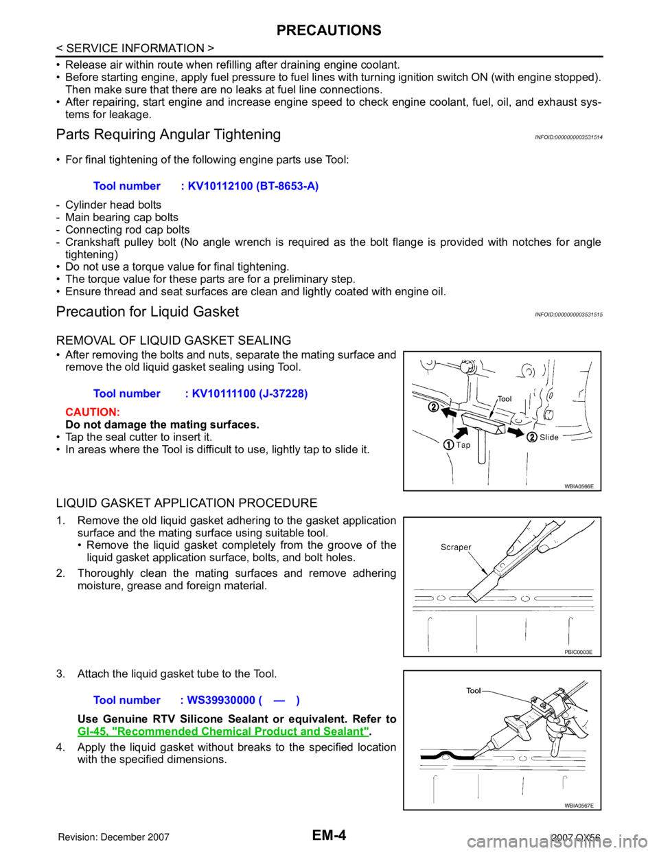
REMOVAL OF LIQUID GASKET SEALING
• After removing the bolts and nuts, separate the mating surface and
remove the old liquid gasket sealing using Tool.
CAUTION:
Do not damage the mating surfaces.
• Tap the seal cutter to insert it.
• In areas where the Tool is difficult to use, lightly tap to slide it.
LIQUID GASKET APPLICATION PROCEDURE
1. Remove the old liquid gasket adhering to the gasket application surface and the mating surface using suitable tool.
• Remove the liquid gasket completely from the groove of theliquid gasket application surface, bolts, and bolt holes.
2. Thoroughly clean the mating surfaces and remove adhering moisture, grease and foreign material.
3. Attach the liquid gasket tube to the Tool. Use Genuine RTV Silicone Seal ant or equivalent. Refer to
GI-45, "
Recommended Chemical Product and Sealant".
4. Apply the liquid gasket without breaks to the specified location with the specified dimensions.Tool number : KV10112100 (BT-8653-A)
Tool number : KV10111100 (J-37228)
WBIA0566E
PBIC0003E
Tool number : WS39930000 ( — )
WBIA0567E
Page 1814 of 3061
EM-44
< SERVICE INFORMATION >
TIMING CHAIN
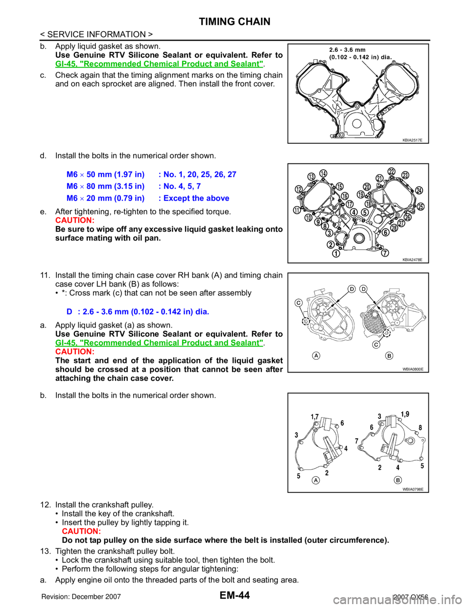
b. Apply liquid gasket as shown.Use Genuine RTV Silicone Seal ant or equivalent. Refer to
GI-45, "
Recommended Chemical Product and Sealant".
c. Check again that the timing alignment marks on the timing chain and on each sprocket are aligned. Then install the front cover.
d. Install the bolts in the numerical order shown.
e. After tightening, re-tighten to the specified torque. CAUTION:
Be sure to wipe off any excessive liquid gasket leaking onto
surface mating with oil pan.
11. Install the timing chain case cover RH bank (A) and timing chain case cover LH bank (B) as follows:
• *: Cross mark (c) that can not be seen after assembly
a. Apply liquid gasket (a) as shown. Use Genuine RTV Silicone Seal ant or equivalent. Refer to
GI-45, "
Recommended Chemical Product and Sealant".
CAUTION:
The start and end of the appl ication of the liquid gasket
should be crossed at a position that cannot be seen after
attaching the chain case cover.
b. Install the bolts in the numerical order shown.
12. Install the crankshaft pulley. • Install the key of the crankshaft.
• Insert the pulley by lightly tapping it.
CAUTION:
Do not tap pulley on the side surface where th e belt is installed (outer circumference).
13. Tighten the crankshaft pulley bolt. • Lock the crankshaft using suitable tool, then tighten the bolt.
• Perform the following steps for angular tightening:
a. Apply engine oil onto the threaded parts of the bolt and seating area.
KBIA2517E
M6 × 50 mm (1.97 in) : No. 1, 20, 25, 26, 27
M6 × 80 mm (3.15 in) : No. 4, 5, 7
M6 × 20 mm (0.79 in) : Except the above
KBIA2478E
D : 2.6 - 3.6 mm (0.102 - 0.142 in) dia.
WBIA0800E
WBIA0798E
Page 1853 of 3061
CYLINDER BLOCK
EM-83
< SERVICE INFORMATION >
C
D
E
F
G
H
I
J
K
L
MA
EM
N
P O
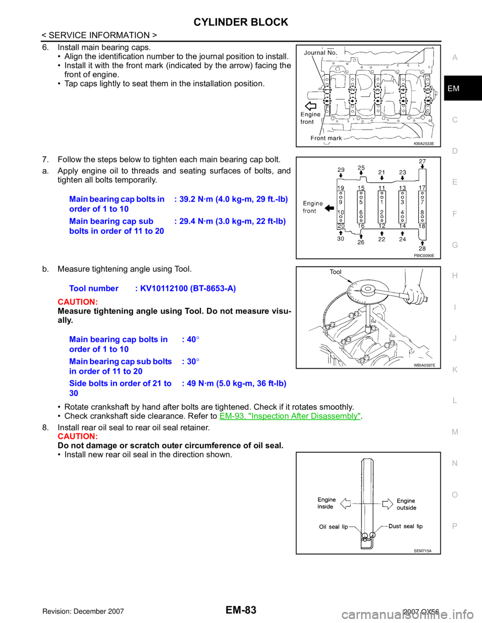
6. Install main bearing caps.
• Align the identification number to the journal position to install.
• Install it with the front mark (indicated by the arrow) facing the
front of engine.
• Tap caps lightly to seat them in the installation position.
7. Follow the steps below to tighten each main bearing cap bolt.
a. Apply engine oil to threads and seating surfaces of bolts, and
tighten all bolts temporarily.
b. Measure tightening angle using Tool.
CAUTION:
Measure tightening angle using Tool. Do not measure visu-
ally.
• Rotate crankshaft by hand after bolts are tightened. Check if it rotates smoothly.
• Check crankshaft side clearance. Refer to EM-93, "
Inspection After Disassembly".
8. Install rear oil seal to rear oil seal retainer.
CAUTION:
Do not damage or scratch outer circumference of oil seal.
• Install new rear oil seal in the direction shown.
KBIA2533E
Main bearing cap bolts in
order of 1 to 10: 39.2 N·m (4.0 kg-m, 29 ft.-lb)
Main bearing cap sub
bolts in order of 11 to 20: 29.4 N·m (3.0 kg-m, 22 ft-lb)
PBIC0090E
Tool number : KV10112100 (BT-8653-A)
Main bearing cap bolts in
order of 1 to 10: 40°
Main bearing cap sub bolts
in order of 11 to 20: 30°
Side bolts in order of 21 to
30: 49 N·m (5.0 kg-m, 36 ft-lb)
WBIA0597E
SEM715A