2007 INFINITI QX56 check engine light
[x] Cancel search: check engine lightPage 2359 of 3061
LU-14
< SERVICE INFORMATION >
OIL PUMP
OIL PUMP
Removal and InstallationINFOID:0000000003531559
REMOVAL
1. Remove front cover. Refer to EM-38, "Removal and Installation".
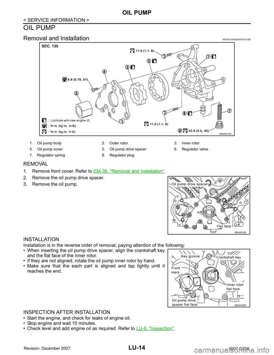
2. Remove the oil pump drive spacer.
3. Remove the oil pump.
INSTALLATION
Installation is in the reverse order of removal, paying attention of the following:
• When inserting the oil pump drive spacer, align the crankshaft key
and the flat face of the inner rotor.
• If they are not aligned, rotate the oil pump inner rotor by hand.
• Make sure that the each part is aligned and tap lightly until it
reaches the end.
INSPECTION AFTER INSTALLATION
• Start the engine, and check for leaks of engine oil.
• Stop engine and wait 10 minutes.
• Check level and add engine oil as required. Refer to LU-8, "
Inspection".
WBIA0415E
1. Oil pump body 2. Outer rotor 3. Inner rotor
4. Oil pump cover 5. Oil pump drive spacer 6. Regulator valve
7. Regulator spring 8. Regulator plug
KBIA2512E
KBIA2490E
Page 2376 of 3061
MA-14
< SERVICE INFORMATION >
ENGINE MAINTENANCE
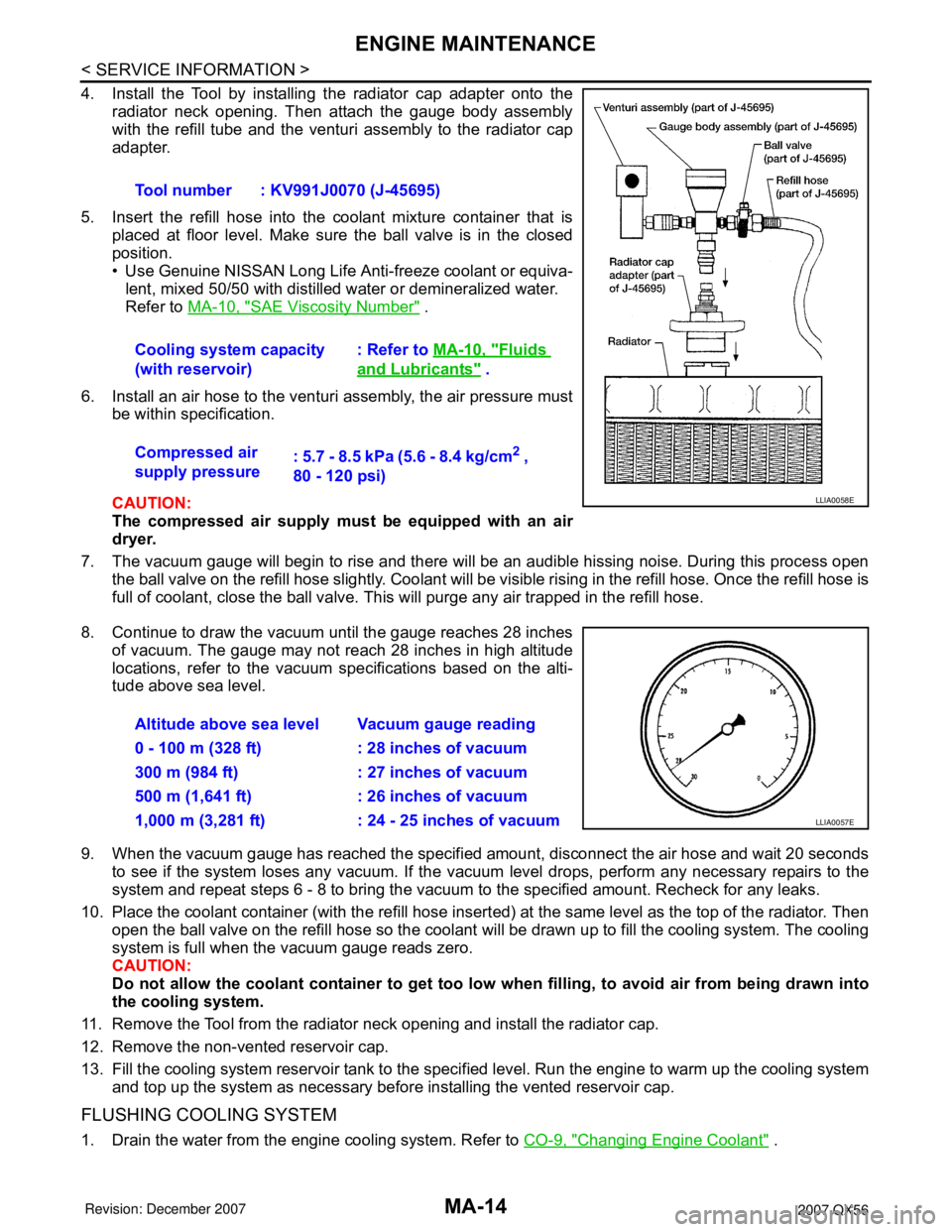
4. Install the Tool by installing the radiator cap adapter onto the
radiator neck opening. Then attach the gauge body assembly
with the refill tube and the venturi assembly to the radiator cap
adapter.
5. Insert the refill hose into the coolant mixture container that is
placed at floor level. Make sure the ball valve is in the closed
position.
• Use Genuine NISSAN Long Life Anti-freeze coolant or equiva-
lent, mixed 50/50 with distilled water or demineralized water.
Refer to MA-10, "
SAE Viscosity Number" .
6. Install an air hose to the venturi assembly, the air pressure must
be within specification.
CAUTION:
The compressed air supply must be equipped with an air
dryer.
7. The vacuum gauge will begin to rise and there will be an audible hissing noise. During this process open
the ball valve on the refill hose slightly. Coolant will be visible rising in the refill hose. Once the refill hose is
full of coolant, close the ball valve. This will purge any air trapped in the refill hose.
8. Continue to draw the vacuum until the gauge reaches 28 inches
of vacuum. The gauge may not reach 28 inches in high altitude
locations, refer to the vacuum specifications based on the alti-
tude above sea level.
9. When the vacuum gauge has reached the specified amount, disconnect the air hose and wait 20 seconds
to see if the system loses any vacuum. If the vacuum level drops, perform any necessary repairs to the
system and repeat steps 6 - 8 to bring the vacuum to the specified amount. Recheck for any leaks.
10. Place the coolant container (with the refill hose inserted) at the same level as the top of the radiator. Then
open the ball valve on the refill hose so the coolant will be drawn up to fill the cooling system. The cooling
system is full when the vacuum gauge reads zero.
CAUTION:
Do not allow the coolant container to get too low when filling, to avoid air from being drawn into
the cooling system.
11. Remove the Tool from the radiator neck opening and install the radiator cap.
12. Remove the non-vented reservoir cap.
13. Fill the cooling system reservoir tank to the specified level. Run the engine to warm up the cooling system
and top up the system as necessary before installing the vented reservoir cap.
FLUSHING COOLING SYSTEM
1. Drain the water from the engine cooling system. Refer to CO-9, "Changing Engine Coolant" . Tool number : KV991J0070 (J-45695)
Cooling system capacity
(with reservoir): Refer to MA-10, "
Fluids
and Lubricants" .
Compressed air
supply pressure: 5.7 - 8.5 kPa (5.6 - 8.4 kg/cm
2 ,
80 - 120 psi)
LLIA0058E
Altitude above sea level Vacuum gauge reading
0 - 100 m (328 ft) : 28 inches of vacuum
300 m (984 ft) : 27 inches of vacuum
500 m (1,641 ft) : 26 inches of vacuum
1,000 m (3,281 ft) : 24 - 25 inches of vacuum
LLIA0057E
Page 2498 of 3061
STEERING WHEEL
PS-7
< SERVICE INFORMATION >
C
D
E
F
H
I
J
K
L
MA
B
PS
N
O
P
STEERING WHEEL
On-Vehicle Inspection and ServiceINFOID:0000000003532824
CHECKING CONDITION OF INSTALLATION
• Check installation condition of steering gear assembly, front suspension, axle and steering column.
• Check if movement exists when steering wheel is moved up and down, to the left and right and to the axial
direction.
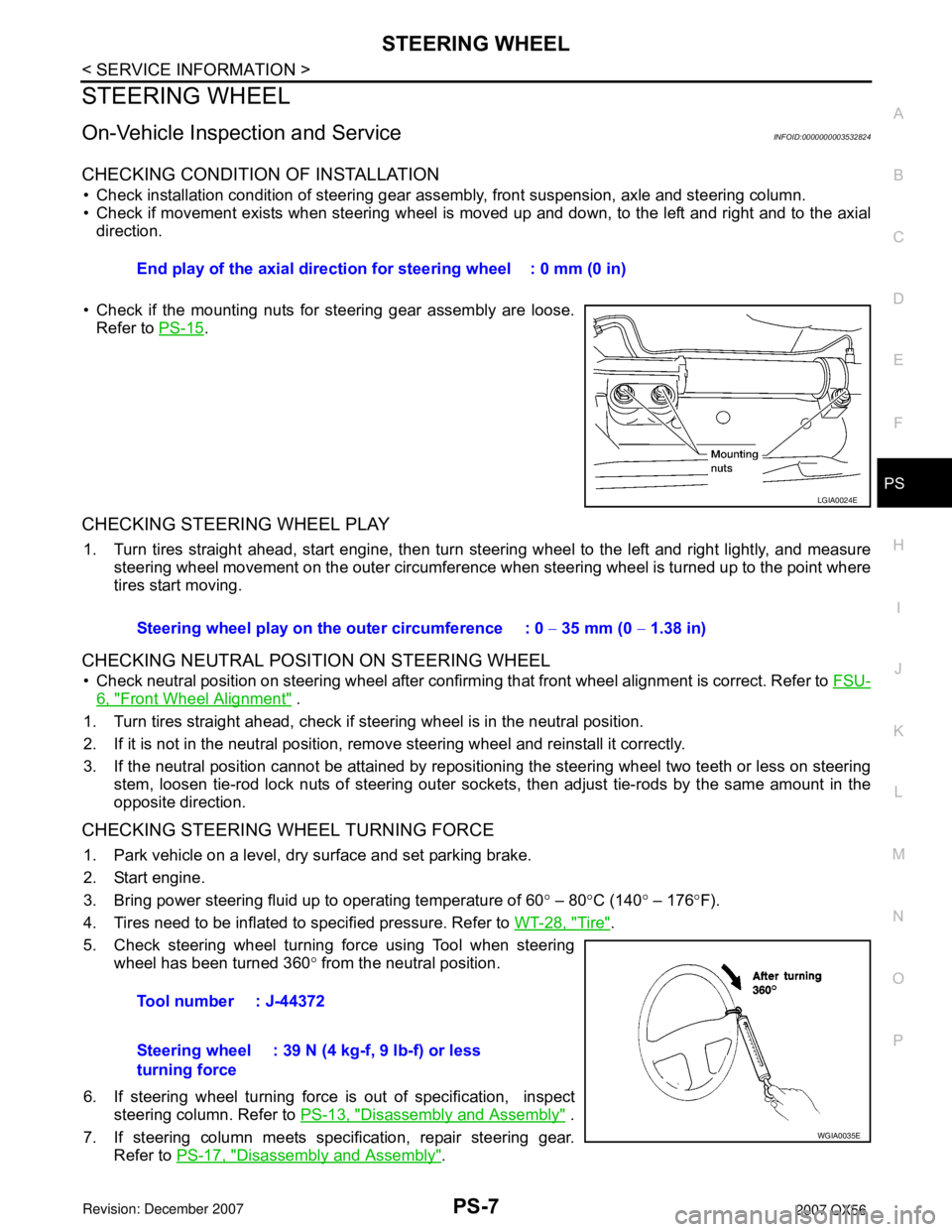
• Check if the mounting nuts for steering gear assembly are loose.
Refer to PS-15
.
CHECKING STEERING WHEEL PLAY
1. Turn tires straight ahead, start engine, then turn steering wheel to the left and right lightly, and measure
steering wheel movement on the outer circumference when steering wheel is turned up to the point where
tires start moving.
CHECKING NEUTRAL POSITION ON STEERING WHEEL
• Check neutral position on steering wheel after confirming that front wheel alignment is correct. Refer to FSU-
6, "Front Wheel Alignment" .
1. Turn tires straight ahead, check if steering wheel is in the neutral position.
2. If it is not in the neutral position, remove steering wheel and reinstall it correctly.
3. If the neutral position cannot be attained by repositioning the steering wheel two teeth or less on steering
stem, loosen tie-rod lock nuts of steering outer sockets, then adjust tie-rods by the same amount in the
opposite direction.
CHECKING STEERING WHEEL TURNING FORCE
1. Park vehicle on a level, dry surface and set parking brake.
2. Start engine.
3. Bring power steering fluid up to operating temperature of 60° – 80°C (140° – 176°F).
4. Tires need to be inflated to specified pressure. Refer to WT-28, "
Tire".
5. Check steering wheel turning force using Tool when steering
wheel has been turned 360° from the neutral position.
6. If steering wheel turning force is out of specification, inspect
steering column. Refer to PS-13, "
Disassembly and Assembly" .
7. If steering column meets specification, repair steering gear.
Refer to PS-17, "
Disassembly and Assembly". End play of the axial direction for steering wheel : 0 mm (0 in)
LGIA0024E
Steering wheel play on the outer circumference : 0 − 35 mm (0 − 1.38 in)
Tool number : J-44372
Steering wheel
turning force: 39 N (4 kg-f, 9 lb-f) or less
WGIA0035E
Page 2537 of 3061
SQUEAK AND RATTLE TROUBLE DIAGNOSIS
RF-5
< SERVICE INFORMATION >
C
D
E
F
G
H
J
K
L
MA
B
RF
N
O
P
If the noise can be duplicated easily during the test drive, to help identify the source of the noise, try to dupli-
cate the noise with the vehicle stopped by doing one or all of the following:
1) Close a door.
2) Tap or push/pull around the area where the noise appears to be coming from.
3) Rev the engine.
4) Use a floor jack to recreate vehicle "twist".
5) At idle, apply engine load (electrical load, half-clutch on M/T model, drive position on A/T model).
6) Raise the vehicle on a hoist and hit a tire with a rubber hammer.
• Drive the vehicle and attempt to duplicate the conditions the customer states exist when the noise occurs.
• If it is difficult to duplicate the noise, drive the vehicle slowly on an undulating or rough road to stress the
vehicle body.
CHECK RELATED SERVICE BULLETINS
After verifying the customer concern or symptom, check ASIST for Technical Service Bulletins (TSBs) related
to that concern or symptom.
If a TSB relates to the symptom, follow the procedure to repair the noise.
LOCATE THE NOISE AND IDENTIFY THE ROOT CAUSE
1. Narrow down the noise to a general area. To help pinpoint the source of the noise, use a listening tool
(Chassis Ear: J-39570, Engine Ear: J-39565 and mechanic's stethoscope).
2. Narrow down the noise to a more specific area and identify the cause of the noise by:
• Removing the components in the area that you suspect the noise is coming from.
Do not use too much force when removing clips and fasteners, otherwise clips and fastener can be broken
or lost during the repair, resulting in the creation of new noise.
• Tapping or pushing/pulling the component that you suspect is causing the noise.
Do not tap or push/pull the component with excessive force, otherwise the noise will be eliminated only tem-
porarily.
• Feeling for a vibration with your hand by touching the component(s) that you suspect is (are) causing the
noise.
• Placing a piece of paper between components that you suspect are causing the noise.
• Looking for loose components and contact marks.
Refer to RF-6, "
Generic Squeak and Rattle Troubleshooting" .
REPAIR THE CAUSE
• If the cause is a loose component, tighten the component securely.
• If the cause is insufficient clearance between components:
- Separate components by repositioning or loosening and retightening the component, if possible.
- Insulate components with a suitable insulator such as urethane pads, foam blocks, felt cloth tape or ure-
thane tape. A NISSAN Squeak and Rattle Kit (J-43980) is available through your authorized NISSAN Parts
Department.
CAUTION:
Do not use excessive force as many components are constructed of plastic and may be damaged.
Always check with the Parts Department for the latest parts information.
The following materials are contained in the NISSAN Squeak and Rattle Kit (J-43980). Each item can be
ordered separately as needed.
URETHANE PADS [1.5 mm (0.059 in) thick]
Insulates connectors, harness, etc.
76268-9E005: 100×135 mm (3.94×5.31 in)
76884-71L01: 60×85 mm (2.36×3.35 in)
76884-71L02: 15×25 mm (0.59×0.98 in)
INSULATOR (Foam blocks)
Insulates components from contact. Can be used to fill space behind a panel.
73982-9E000: 45 mm (1.77 in) thick, 50×50 mm (1.97×1.97 in)
73982-50Y00: 10 mm (0.39 in) thick, 50×50 mm (1.97×1.97 in)
INSULATOR (Light foam block)
80845-71L00: 30 mm (1.18 in) thick, 30×50 mm (1.18×1.97 in)
FELT CLOTH TAPE
Used to insulate where movement does not occur. Ideal for instrument panel applications.
68370-4B000: 15×25 mm (0.59×0.98 in) pad/68239-13E00: 5 mm (0.20 in) wide tape roll.
The following materials, not found in the kit, can also be used to repair squeaks and rattles.
UHMW (TEFLON) TAPE
Page 2678 of 3061
SE-6
< SERVICE INFORMATION >
SQUEAK AND RATTLE TROUBLE DIAGNOSIS
If the noise can be duplicated easily during the test drive, to help identify the source of the noise, try to dupli-
cate the noise with the vehicle stopped by doing one or all of the following:
1) Close a door.
2) Tap or push/pull around the area where the noise appears to be coming from.
3) Rev the engine.
4) Use a floor jack to recreate vehicle “twist”.
5) At idle, apply engine load (electrical load, half-clutch on M/T model, drive position on A/T model).
6) Raise the vehicle on a hoist and hit a tire with a rubber hammer.
• Drive the vehicle and attempt to duplicate the conditions the customer states exist when the noise occurs.
• If it is difficult to duplicate the noise, drive the vehicle slowly on an undulating or rough road to stress the
vehicle body.
CHECK RELATED SERVICE BULLETINS
After verifying the customer concern or symptom, check ASIST for Technical Service Bulletins (TSBs) related
to that concern or symptom.
If a TSB relates to the symptom, follow the procedure to repair the noise.
LOCATE THE NOISE AND IDENTIFY THE ROOT CAUSE
1. Narrow down the noise to a general area.To help pinpoint the source of the noise, use a listening tool
(Chassis Ear: J-39570, Engine Ear: J-39565 and mechanic's stethoscope).
2. Narrow down the noise to a more specific area and identify the cause of the noise by:
• removing the components in the area that you suspect the noise is coming from.
Do not use too much force when removing clips and fasteners, otherwise clips and fasteners can be broken
or lost during the repair, resulting in the creation of new noise.
• tapping or pushing/pulling the component that you suspect is causing the noise.
Do not tap or push/pull the component with excessive force, otherwise the noise will be eliminated only tem-
porarily.
• feeling for a vibration with your hand by touching the component(s) that you suspect is (are) causing the
noise.
• placing a piece of paper between components that you suspect are causing the noise.
• looking for loose components and contact marks.
Refer to SE-7, "
Generic Squeak and Rattle Troubleshooting" .
REPAIR THE CAUSE
• If the cause is a loose component, tighten the component securely.
• If the cause is insufficient clearance between components:
- separate components by repositioning or loosening and retightening the component, if possible.
- insulate components with a suitable insulator such as urethane pads, foam blocks, felt cloth tape or urethane
tape. A NISSAN Squeak and Rattle Kit (J-43980) is available through your authorized NISSAN Parts Depart-
ment.
CAUTION:
Do not use excessive force as many components are constructed of plastic and may be damaged.
Always check with the Parts Department for the latest parts information.
The following materials are contained in the NISSAN Squeak and Rattle Kit (J-43980). Each item can be
ordered separately as needed.
URETHANE PADS [1.5 mm (0.059 in) thick]
Insulates connectors, harness, etc.
76268-9E005: 100×135 mm (3.94×5.31 in)/76884-71L01: 60×85 mm (2.36×3.35 in)/76884-71L02: 15×25
mm (0.59×0.98 in)
INSULATOR (Foam blocks)
Insulates components from contact. Can be used to fill space behind a panel.
73982-9E000: 45 mm (1.77 in) thick, 50×50 mm (1.97×1.97 in)/73982-50Y00: 10 mm (0.39 in) thick,
50×50 mm (1.97×1.97 in)
INSULATOR (Light foam block)
80845-71L00: 30 mm (1.18 in) thick, 30×50 mm (1.18×1.97 in)
FELT CLOTH TAPE
Used to insulate where movement does not occur. Ideal for instrument panel applications.
68370-4B000: 15×25 mm (0.59×0.98 in) pad/68239-13E00: 5 mm (0.20 in) wide tape roll. The following
materials not found in the kit can also be used to repair squeaks and rattles.
UHMW (TEFLON) TAPE
Insulates where slight movement is present. Ideal for instrument panel applications.
Page 2856 of 3061
TF-34
< SERVICE INFORMATION >
TROUBLE DIAGNOSIS
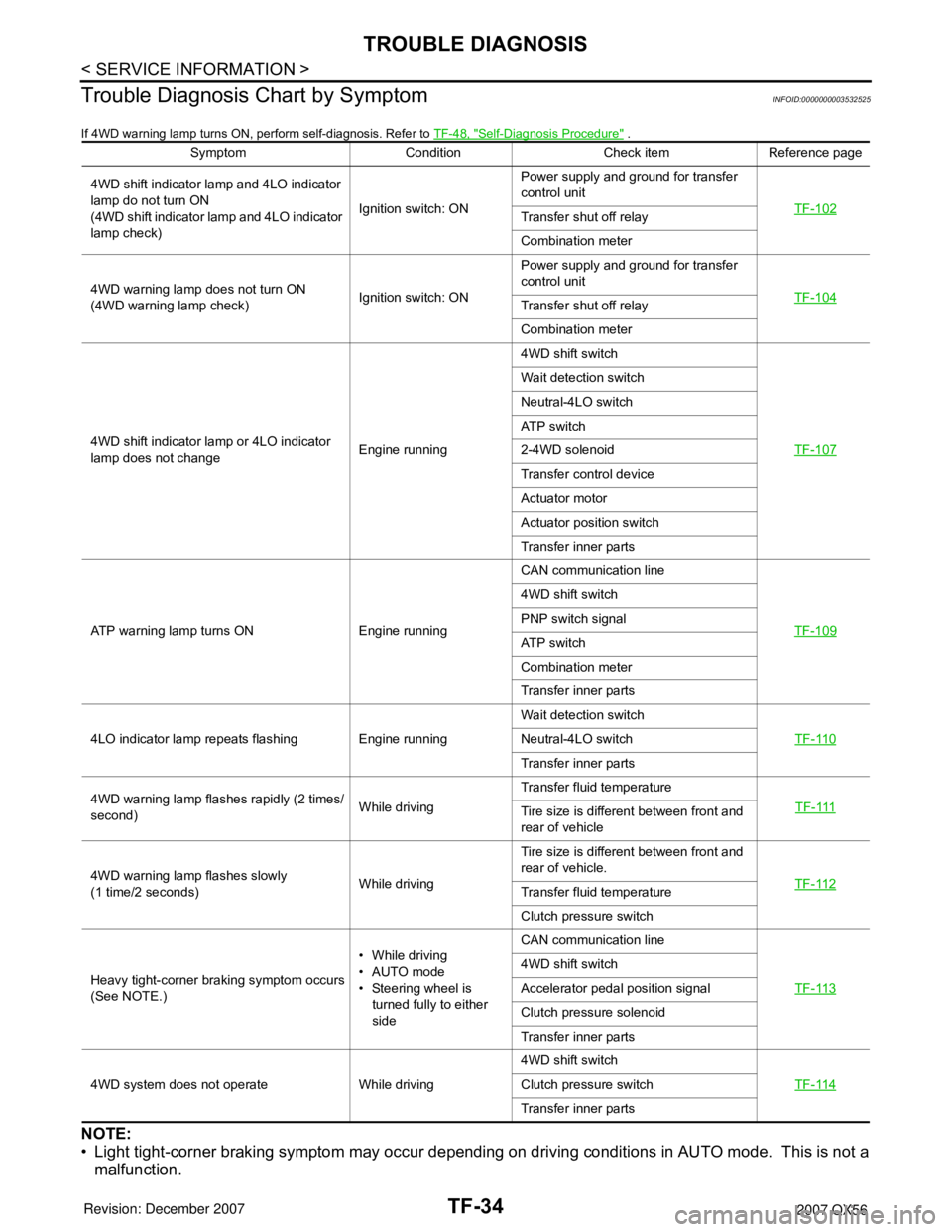
Trouble Diagnosis Chart by Symptom
INFOID:0000000003532525
If 4WD warning lamp turns ON, perform self-diagnosis. Refer to TF-48, "Self-Diagnosis Procedure" .
NOTE:
• Light tight-corner braking symptom may occur depending on driving conditions in AUTO mode. This is not a
malfunction.
Symptom Condition Check item Reference page
4WD shift indicator lamp and 4LO indicator
lamp do not turn ON
(4WD shift indicator lamp and 4LO indicator
lamp check)Ignition switch: ONPower supply and ground for transfer
control unit
TF-102
Transfer shut off relay
Combination meter
4WD warning lamp does not turn ON
(4WD warning lamp check)Ignition switch: ONPower supply and ground for transfer
control unit
TF-104
Transfer shut off relay
Combination meter
4WD shift indicator lamp or 4LO indicator
lamp does not changeEngine running4WD shift switch
TF-107
Wait detection switch
Neutral-4LO switch
ATP switch
2-4WD solenoid
Transfer control device
Actuator motor
Actuator position switch
Transfer inner parts
ATP warning lamp turns ON Engine runningCAN communication line
TF-109
4WD shift switch
PNP switch signal
ATP switch
Combination meter
Transfer inner parts
4LO indicator lamp repeats flashing Engine runningWait detection switch
TF-110
Neutral-4LO switch
Transfer inner parts
4WD warning lamp flashes rapidly (2 times/
second)While drivingTransfer fluid temperature
TF-111
Tire size is different between front and
rear of vehicle
4WD warning lamp flashes slowly
(1 time/2 seconds)While drivingTire size is different between front and
rear of vehicle.
TF-112
Transfer fluid temperature
Clutch pressure switch
Heavy tight-corner braking symptom occurs
(See NOTE.)• While driving
•AUTO mode
• Steering wheel is
turned fully to either
sideCAN communication line
TF-113
4WD shift switch
Accelerator pedal position signal
Clutch pressure solenoid
Transfer inner parts
4WD system does not operate While driving4WD shift switch
TF-114
Clutch pressure switch
Transfer inner parts
Page 2935 of 3061
TROUBLE DIAGNOSIS FOR SYMPTOMS
TF-113
< SERVICE INFORMATION >
C
E
F
G
H
I
J
K
L
MA
B
TF
N
O
P
NG >> GO TO 5.
5.CHECK TRANSFER CONTROL UNIT
Check transfer control unit input/output signal. Refer to TF-35, "
Transfer Control Unit Input/Output Signal Ref-
erence Value".
OK or NG
OK >> Inspection End.
NG >> Check transfer control unit pin terminals for damage or loose connection with harness connector.
If any items are damaged, repair or replace damaged parts.
Heavy Tight-corner Braking Symptom OccursINFOID:0000000003532560
SYMPTOM:
Heavy tight-corner braking symptom occurs when vehicle is driven in AUTO mode and steering wheel
is turned fully to either side.
DIAGNOSTIC PROCEDURE
NOTE:
• Light tight-corner braking symptom may occur depending on driving conditions in AUTO mode. This is not a
malfunction.
• Heavy tight-corner braking symptom occurs when vehicle is driven in the following conditions: 4WD shift
switch is "4H" or "4LO", steering wheel is turned fully to either side.
1.CHECK SYSTEM FOR CAN COMMUNICATION LINE
Perform self-diagnosis. Refer to TF-48, "
Self-Diagnosis Procedure".
Is "CAN COMM CIRCUIT [U1000]" displayed?
YES >> Perform trouble diagnosis for CAN communication line. Refer to TF-99, "CAN Communication
Line" .
NO >> GO TO 2.
2.CHECK SYSTEM FOR 4WD SHIFT SWITCH
Perform trouble diagnosis for 4WD shift switch system. Refer to TF-57, "
4WD Shift Switch".
OK or NG
OK >> GO TO 3.
NG >> Repair or replace damaged parts.
3.CHECK ACCELERATOR PEDAL POSITION SIGNAL CIRCUIT
Perform self diagnosis for ECM. Refer to E C - 111 , "
CONSULT-II Function (ENGINE)".
Is any malfunction deteced by self-diagnosis?
YES >> Check the malfunctioning system.
NO >> GO TO 4.
4.CHECK SYSTEM FOR CLUTCH PRESSURE SOLENOID
Perform trouble diagnosis for clutch pressure solenoid system. Refer toTF-92, "
Clutch Pressure Switch" .
OK or NG
OK >> GO TO 5.
NG >> Repair or replace damaged parts.
5.SYMPTOM CHECK
Check again.
OK or NG
OK >> Inspection End.
NG >> GO TO 6.
6.CHECK TRANSFER CONTROL UNIT
Check transfer control unit input/output signal. Refer to TF-35, "
Transfer Control Unit Input/Output Signal Ref-
erence Value".
OK or NG