2007 INFINITI QX56 Parking brake
[x] Cancel search: Parking brakePage 1022 of 3061
COMBINATION METERSDI-11
< SERVICE INFORMATION >
C
DE
F
G H
I
J
L
M A
B
DI
N
O P
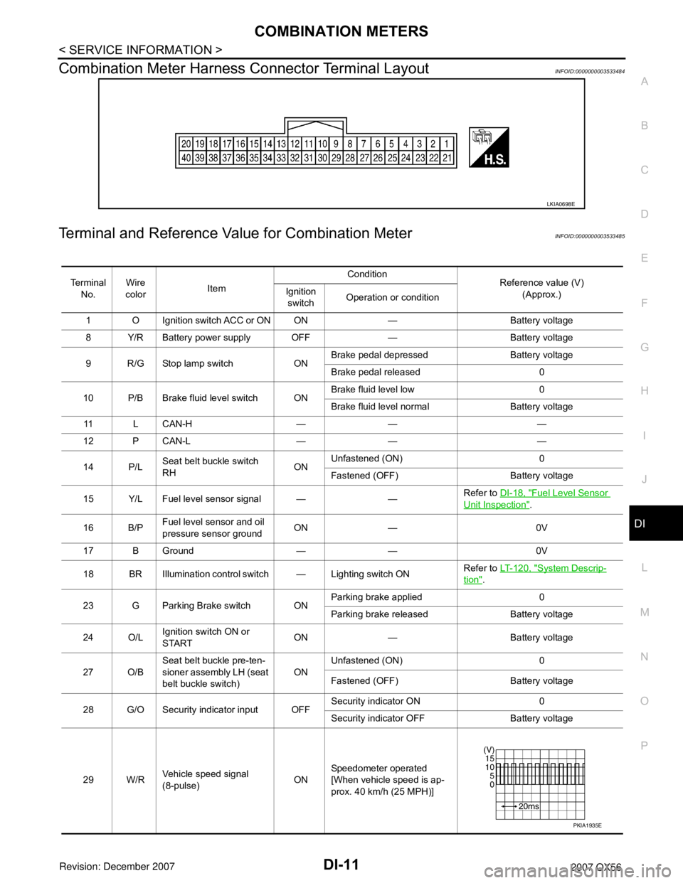
Combination Meter Harness Connector Terminal LayoutINFOID:0000000003533484
Terminal and Reference Va lue for Combination MeterINFOID:0000000003533485
LKIA0698E
Te r m i n a l
No. Wire
color Item Condition
Reference value (V)
(Approx.)
Ignition
switch Operation or condition
1 O Ignition switch ACC or ON ON — Battery voltage
8 Y/R Battery power supply OFF — Battery voltage
9 R/G Stop lamp switch ON Brake pedal depressed Battery voltage
Brake pedal released 0
10 P/B Brake fluid level switch ON Brake fluid level low 0
Brake fluid level normal Battery voltage
11 L C A N - H — — —
12 P CAN-L — — —
14 P/L Seat belt buckle switch
RH ONUnfastened (ON) 0
Fastened (OFF) Battery voltage
15 Y/L Fuel level sensor signal — — Refer to
DI-18, "
Fuel Level Sensor
Unit Inspection".
16 B/P Fuel level sensor and oil
pressure sensor ground ON — 0V
17 B Ground — — 0V
18 BR Illumination control switch — Lighting switch ON Refer to
LT- 1 2 0 , "
System Descrip-
tion".
23 G Parking Brake switch ON Parking brake applied 0
Parking brake released Battery voltage
24 O/L Ignition switch ON or
START ON — Battery voltage
27 O/B Seat belt buckle pre-ten-
sioner assembly LH (seat
belt buckle switch) ON
Unfastened (ON) 0
Fastened (OFF) Battery voltage
28 G/O Security indicator input OFF Security indicator ON 0
Security indicator
OFF Battery voltage
29 W/R Vehicle speed signal
(8-pulse) ONSpeedometer operated
[When vehicle speed is ap-
prox. 40 km/h (25 MPH)]
PKIA1935E
Page 1161 of 3061
EC-78
< SERVICE INFORMATION >
BASIC SERVICE PROCEDURE
3. Turn ignition switch OFF wait at least 10 seconds.
Make sure that throttle valve moves during above 10 seconds by confirming the operating sound.
Idle Air Volume LearningINFOID:0000000003531615
DESCRIPTION
Idle Air Volume Learning is an operation to learn the idle air volume that keeps each engine within the specific
range. It must be performed under any of the following conditions:
• Each time electric throttle control actuator or ECM is replaced.
• Idle speed or ignition timing is out of specification.
PREPARATION
Before performing Idle Air Volume Learning, make sure that all of the following conditions are satisfied.
Learning will be cancelled if any of the following conditions are missed for even a moment.
• Battery voltage: More than 12.9V (At idle)
• Engine coolant temperature: 70 - 100°C (158 - 212°F)
• Park/Neutral position (PNP) switch: ON
• Electric load switch: OFF
(Air conditioner, headlamp, rear window defogger)
On vehicles equipped with daytime light systems, if the parking brake is applied before the engine is
start the headlamp will not be illuminated.
• Steering wheel: Neutral (Straight-ahead position)
• Vehicle speed: Stopped
• Transmission: Warmed-up
- With CONSULT-II: Drive vehicle until “ATF TEMP SE 1” in “DATA MONITOR” mode of “A/T” system indi-
cates less than 0.9V.
- Without CONSULT-II: Drive vehicle for 10 minutes.
OPERATION PROCEDURE
With CONSULT-II
1. Perform EC-77, "Accelerator Pedal Released Position Learning" .
2. Perform EC-77, "
Throttle Valve Closed Position Learning" .
3. Start engine and warm it up to normal operating temperature.
4. Check that all items listed under the topic PREPARATION (previously mentioned) are in good order.
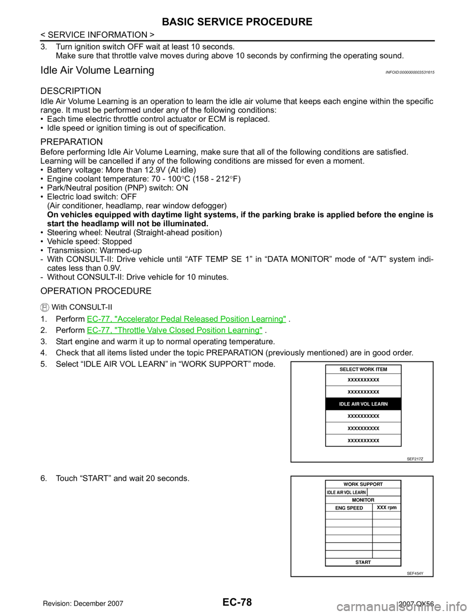
5. Select “IDLE AIR VOL LEARN” in “WORK SUPPORT” mode.
6. Touch “START” and wait 20 seconds.
SEF217Z
SEF454Y
Page 1984 of 3061
GI-18
< SERVICE INFORMATION >
HOW TO USE THIS MANUAL
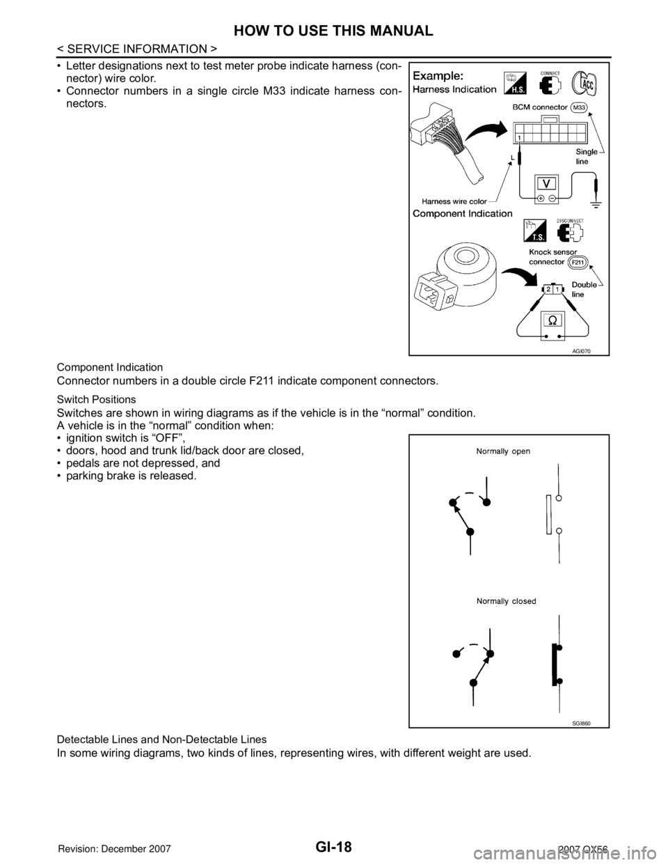
• Letter designations next to test meter probe indicate harness (con-
nector) wire color.
• Connector numbers in a single circle M33 indicate harness con-
nectors.
Component Indication
Connector numbers in a double circle F211 indicate component connectors.
Switch Positions
Switches are shown in wiring diagrams as if the vehicle is in the “normal” condition.
A vehicle is in the “normal” condition when:
• ignition switch is “OFF”,
• doors, hood and trunk lid/back door are closed,
• pedals are not depressed, and
• parking brake is released.
Detectable Lines and Non-Detectable Lines
In some wiring diagrams, two kinds of lines, representing wires, with different weight are used.
AGI070
SGI860
Page 2110 of 3061
IDX-6
ALPHABETICAL INDEX
Line pressure solenoid valve ........................... AT-118
Line pressure switch (Transfer) .......... TF-154, TF-167
Line pressure test (A/T) ..................................... AT-52
Location of electrical units ................................. PG-65
Low coast brake solenoid valve ......... AT-151, AT-153
Low tire pressure warning system ...................... WT-8
Low tire pressure warning system - trouble diagnoses .
WT-11
Low tire pressure warning system - Wiring diagram .....
WT-11
Lubricant (R134a) A/C ..................................... ATC-22
Lubricants ......................................................... MA-11
Lubrication circuit (engine) ................................... LU-6
Lubrication oil A/C ............................................ ATC-22
Lubrication-locks, hinges and hood latches ...... MA-31
M
MAFS - Wiring diagram ..................... EC-200
, EC-208
Magnet clutch ............................... ATC-115, ATC-180
MAIN - Wiring diagram ...................... EC-150, AT-163
Main oil pump (Transfer) ..................... TF-154, TF-167
Mainshaft (Transfer) ........................... TF-154, TF-167
Maintenance (engine)Schedule 1 ....................... MA-7
Maintenance (engine)Schedule 2 ....................... MA-9
Major overhaul (Final drive) ............................. FFD-14
Major overhaul (Transfer) ................................ TF-146
Malfunction indicator lamp (MIL) ........................ EC-65
Map lamp .......................................................... LT-111
Mass air flow sensor (MAFS) ............. EC-197, EC-206
Meter ..................................................................... DI-5
METER - Wiring diagram ...................................... DI-9
MIL data link connectors circuit ....................... EC-697
MIL/DL - Wiring diagram .................................. EC-697
MIRROR - Wiring diagram ................................ GW-87
Misfire .............................................................. EC-350
Mode door control linkage adjustment ............. ATC-65
Mode door motor ............................ ATC-62, ATC-165
Model variation ................................................... GI-48
Multiport fuel injection (MFI) system .................. EC-25
Multiport fuel injection precautions ....................... GI-6
Multi-remote control system - See Remote keyless entry
system ............................................................... BL-40
N
NATS - Wiring diagram .................................... BL-130
NAVI - Wiring diagram ....................................... AV-86
NAVI Control Unit .............................................. AV-83
Navigation system ............................................. AV-81
Neutral-4LO switch ............................................ TF-61
NONDTC - Wiring diagram .............................. AT-172
NVH troubleshooting (AX) ................................. FAX-4
NVH troubleshooting (EM) ................................ EM-10
NVH troubleshooting (Final drive) ..................... RFD-7
NVH troubleshooting (Propeller shaft) ................. PR-3
NVH troubleshooting (RAX) .............................. RAX-4
NVH troubleshooting (RSU) .............................. RSU-5
NVH troubleshooting (ST) .................................... PS-5
NVH troubleshooting (Transfer) ......................... TF-10
NVH troubleshooting (WT)NVH troubleshooting (WT) ..
WT-4
NVIS (Nissan vehicle immobilizer system) precautions
GI-3
O
O2H2B1 - Wiring diagram ............................... EC-183
O2H2B2 - Wiring diagram ............................... EC-185
O2S2B1 - Wiring diagram ... EC-279, EC-290, EC-303
O2S2B2 - Wiring diagram ... EC-281, EC-292, EC-305
Oil cooler (engine) .............................................. LU-12
Oil filter ............................................................... LU-11
Oil filter (Transfer) ............................................ TF-143
Oil pan (engine) ................................................ EM-24
Oil pressure (engine) ........................................... LU-8
Oil pressure relief valve (engine) ......................... LU-6
Oil pump (engine) .............................................. LU-14
Oil seal replacement (engine) ........................... EM-60
Oil seal replacement (front of final drive) FFD-8, RFD-9
Oil seal replacement (side of final drive) ......... RFD-11
On board diagnostic system ............................. EC-49
ORVR (On-board Refueling Vapor Recovery) .. EC-40
Overheat ......................................................... EC-504
P
P/SCKT - Wiring diagram ................................. WW-46
Pantograph jack .................................................. GI-42
Park/Neutral position switch ............................ EC-487
Parking brake control ........................................... PB-4
PCV (positive crankcase ventilation) ................ EC-46
Periodic maintenance ......................................... MA-7
Personal lamp .................................................. LT-111
PGC/V - Wiring diagram ................... EC-397, EC-405
PHASE - Wiring diagram ................................ EC-371
PHONE - Wiring diagram ................................... AV-65
Pinion bearing preload diff. ............................. RFD-26
Piston pin inspection ......................................... EM-94
Piston ring inspection ........................................ EM-95
Piston to bore clearance ................................... EM-99
Planetary carrier (Transfer) ................. TF-149, TF-176
PNP/SW - Wiring diagram ... EC-489, AT-101, AT-102
POS - Wiring diagram ..................................... EC-364
POWER - Wiring diagram ................................... PG-6
Power door lock ................................................. BL-16
Power seat ......................................................... SE-81
Power steering fluid level .................................. MA-29
Power steering gear ........................................... PS-15
Power steering oil pump .................................... PS-22
Power steering pressure (PSP) sensor ........... EC-470
Power steering system bleeding .......................... PS-6
Power supply routing .......................................... PG-4
Power window .................................................. GW-15
PRE/SE - Wiring diagram ................. EC-429, EC-435
Precautions (General) ........................................... GI-4
Precautions in repairing high strength steel ..... BL-182
Pressure switch 1 ............................... AT-141, AT-155
Page 2177 of 3061
![INFINITI QX56 2007 Factory Service Manual LAN-46
< SERVICE INFORMATION >[CAN]
TROUBLE DIAGNOSIS
NOTE:
CAN data of the air bag diagnosis sensor unit is not used by usual service work, thus it is omitted.
TYPE 3/TYPE 4
NOTE:
Refer to LAN-37, " INFINITI QX56 2007 Factory Service Manual LAN-46
< SERVICE INFORMATION >[CAN]
TROUBLE DIAGNOSIS
NOTE:
CAN data of the air bag diagnosis sensor unit is not used by usual service work, thus it is omitted.
TYPE 3/TYPE 4
NOTE:
Refer to LAN-37, "](/manual-img/42/57029/w960_57029-2176.png)
LAN-46
< SERVICE INFORMATION >[CAN]
TROUBLE DIAGNOSIS
NOTE:
CAN data of the air bag diagnosis sensor unit is not used by usual service work, thus it is omitted.
TYPE 3/TYPE 4
NOTE:
Refer to LAN-37, "
Abbreviation List" for the abbreviations of the connecting units.
T: Transmit R: Receive
A/C switch/indicator signalTR
RT
1st position switch signal R T
4th position switch signal R T
Distance to empty signal R T
Fuel level low warning signal R T
Fuel level sensor signal R T
Parking brake switch signal R T
Stop lamp switch signal R T
Tow mode switch signal R T
Vehicle speed signalRR T
RRR RRR T
Steering angle sensor signalTR
ABS malfunction signal R T
ABS warning lamp signalRT
Brake pressure sensor signal R T
Brake warning lamp signalRT
SLIP indicator lamp signalRT
TCS malfunction signal R T
VDC malfunction signal R T
VDC OFF indicator lamp signal R R T
VDC operation signal R T
Front wiper stop position signal R T
High beam status signal RT
Hood switch signal R T
Low beam status signal RT
Rear window defogger control signal R R TSignal name/Connecting unit
ECM
TCM
LASER
ICC
ADP
BCM
DISP
HVAC
M&A
STRG
ABS
IPDM-E
Signal name/Connecting unitECM
TCM
LASER
ICC
ADP
BCM
DISP
HVAC
M&A
STRG
4WD
ABS
IPDM-E
A/C compressor request signal TR
Accelerator pedal position signal T R R R R
ASCD CRUISE lamp signal T R
ASCD OD cancel request signal T R
ASCD operation signal T R
ASCD SET lamp signal T R
Battery voltage signal T R
Closed throttle position signal T R R
Page 2179 of 3061
![INFINITI QX56 2007 Factory Service Manual LAN-48
< SERVICE INFORMATION >[CAN]
TROUBLE DIAGNOSIS
NOTE:
CAN data of the air bag diagnosis sensor unit is not used by usual service work, thus it is omitted.
Tire pressure signal T R R
Turn indica INFINITI QX56 2007 Factory Service Manual LAN-48
< SERVICE INFORMATION >[CAN]
TROUBLE DIAGNOSIS
NOTE:
CAN data of the air bag diagnosis sensor unit is not used by usual service work, thus it is omitted.
Tire pressure signal T R R
Turn indica](/manual-img/42/57029/w960_57029-2178.png)
LAN-48
< SERVICE INFORMATION >[CAN]
TROUBLE DIAGNOSIS
NOTE:
CAN data of the air bag diagnosis sensor unit is not used by usual service work, thus it is omitted.
Tire pressure signal T R R
Turn indicator signal T R
A/C switch/indicator signalTR
RT
1st position switch signal R T
4th position switch signal R T
Distance to empty signal R T
Fuel level low warning signal R T
Fuel level sensor signal R T
Parking brake switch signal R T
Stop lamp switch signal R T
Tow mode switch signal R T
Vehicle speed signalRR R T
RRR RRR T
Steering angle sensor signalTR
ABS malfunction signal R T
ABS warning lamp signalRT
Brake pressure sensor signal R T
Brake warning lamp signalRT
SLIP indicator lamp signalRT
TCS malfunction signal R T
VDC malfunction signal R T
VDC OFF indicator lamp signal R R T
VDC operation signal R T
Front wiper stop position signal R T
High beam status signal RT
Hood switch signal R T
Low beam status signal RT
Rear window defogger control signal R R TSignal name/Connecting unit
ECM
TCM
LASER
ICC
ADP
BCM
DISP
HVAC
M&A
STRG
4WD
ABS
IPDM-E
Page 2231 of 3061
LT-24
< SERVICE INFORMATION >
HEADLAMP (FOR CANADA) - DAYTIME LIGHT SYSTEM -
HEADLAMP (FOR CANADA) - DAYTIME LIGHT SYSTEM -
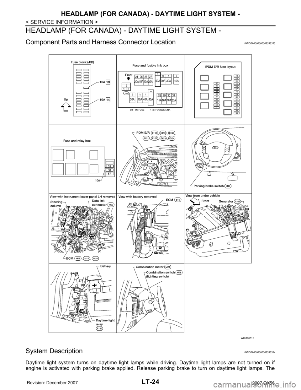
Component Parts and Harness Connector LocationINFOID:0000000003533353
System DescriptionINFOID:0000000003533354
Daytime light system turns on daytime light lamps while driving. Daytime light lamps are not turned on if
engine is activated with parking brake applied. Release parking brake to turn on daytime light lamps. The
WKIA3551E
Page 2232 of 3061
HEADLAMP (FOR CANADA) - DAYTIME LIGHT SYSTEM -
LT-25
< SERVICE INFORMATION >
C
D
E
F
G
H
I
J
L
MA
B
LT
N
O
P
lamps turn off when lighting switch is in the 2ND position or AUTO position (Headlamp is "ON") and when light-
ing switch is in the PASSING position. (Daytime light lamps are not turned off only by parking brake itself.)
A parking brake signal and engine run or stop signal are sent to BCM (body control module) by CAN commu-
nication line.
OUTLINE
Power is supplied at all times
• to ignition relay, located in the IPDM E/R (intelligent power distribution module engine room),
• through 50A fusible link (letter f , located in the fuse and fusible link box)
• to BCM terminal 70,
• through 20A fuse (No. 53, located in the IPDM E/R)
• to CPU (central processing unit) of the IPDM E/R,
• through 10A fuse [No. 19, located in the fuse block (J/B)]
• to combination meter terminal 8, and
• through 10A fuse (No. 45, located in the IPDM E/R)
• to daytime light relay terminals 2 and 5.
When the ignition switch is in ON or START position, power is supplied
• to ignition relay, located in the IPDM E/R,
• through 10A fuse (No. 59, located in the fuse and relay box)
• to BCM terminal 38, and
• through 10A fuse [No. 14, located in the fuse block (J/B)]
• to combination meter terminal 24.
Ground is supplied
• to BCM terminal 67 and
• to combination meter terminal 17
• through grounds M57, M61 and M79.
DAYTIME LIGHT OPERATION
With the engine running, the lighting switch in the OFF or 1ST position and parking brake released, the IPDM
E/R receives input requesting the daytime lights illuminate. This input is communicated across the CAN com-
munication lines. The CPU of the IPDM E/R controls the daytime light relay coil. When energized, this relay
directs power
• through daytime light relay terminal 3
• to front combination lamp LH terminal 2
• through front combination lamp LH terminal 6
• to IPDM E/R terminal 55
• through 10A fuse (No. 35, located in the IPDM E/R)
• through 10A fuse (No. 34, located in the IPDM E/R)
• through IPDM E/R terminal 56
• to front combination lamp RH terminal 6.
Ground is supplied
• to front combination lamp RH terminal 2
• through grounds E9, E15 and E24.
With power and ground supplied, the daytime lights illuminate. The high beam headlamps are now wired in
series and illuminate at a reduced intensity.
COMBINATION SWITCH READING FUNCTION
Refer to BCS-3, "System Description" .
AUTO LIGHT OPERATION
Refer to LT-34, "System Description" .
CAN Communication System DescriptionINFOID:0000000003533355
Refer to LAN-4, "CAN Communication System" .