Page 2486 of 3061
REAR PROPELLER SHAFT
PR-9
< SERVICE INFORMATION >
C
E
F
G
H
I
J
K
L
MA
B
PR
N
O
P
Model 2S1410 4WD
REMOVAL
1. Move the A/T select lever to the N position and release the parking brake.
2. Put matching marks on the rear propeller shaft flange yoke and
the companion flange of the rear final drive as shown.
CAUTION:
For matching marks, use paint. Never damage the rear pro-
peller shaft flange yoke or the companion flange.
3. Remove the bolts, then remove the propeller shaft from the rear
final drive and A/T.
INSPECTION AFTER REMOVAL
• Inspect the propeller shaft run out. If run out exceeds the limit,
replace the propeller shaft assembly.
AWDIA0031ZZ
1. Propeller shaft tube 2. Snap ring 3. Journal bearing
4. Sleeve yoke 5. Journal 6. Flange yoke
⇐Vehicle front
WDIA0049E
Propeller shaft run out limit : 1.02 mm (0.0402 in) or
less
LDIA0121E
Page 2498 of 3061

STEERING WHEEL
PS-7
< SERVICE INFORMATION >
C
D
E
F
H
I
J
K
L
MA
B
PS
N
O
P
STEERING WHEEL
On-Vehicle Inspection and ServiceINFOID:0000000003532824
CHECKING CONDITION OF INSTALLATION
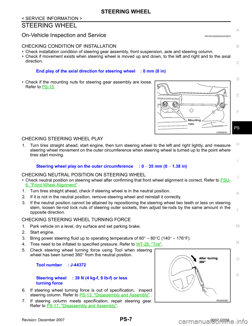
• Check installation condition of steering gear assembly, front suspension, axle and steering column.
• Check if movement exists when steering wheel is moved up and down, to the left and right and to the axial
direction.
• Check if the mounting nuts for steering gear assembly are loose.
Refer to PS-15
.
CHECKING STEERING WHEEL PLAY
1. Turn tires straight ahead, start engine, then turn steering wheel to the left and right lightly, and measure
steering wheel movement on the outer circumference when steering wheel is turned up to the point where
tires start moving.
CHECKING NEUTRAL POSITION ON STEERING WHEEL
• Check neutral position on steering wheel after confirming that front wheel alignment is correct. Refer to FSU-
6, "Front Wheel Alignment" .
1. Turn tires straight ahead, check if steering wheel is in the neutral position.
2. If it is not in the neutral position, remove steering wheel and reinstall it correctly.
3. If the neutral position cannot be attained by repositioning the steering wheel two teeth or less on steering
stem, loosen tie-rod lock nuts of steering outer sockets, then adjust tie-rods by the same amount in the
opposite direction.
CHECKING STEERING WHEEL TURNING FORCE
1. Park vehicle on a level, dry surface and set parking brake.
2. Start engine.
3. Bring power steering fluid up to operating temperature of 60° – 80°C (140° – 176°F).
4. Tires need to be inflated to specified pressure. Refer to WT-28, "
Tire".
5. Check steering wheel turning force using Tool when steering
wheel has been turned 360° from the neutral position.
6. If steering wheel turning force is out of specification, inspect
steering column. Refer to PS-13, "
Disassembly and Assembly" .
7. If steering column meets specification, repair steering gear.
Refer to PS-17, "
Disassembly and Assembly". End play of the axial direction for steering wheel : 0 mm (0 in)
LGIA0024E
Steering wheel play on the outer circumference : 0 − 35 mm (0 − 1.38 in)
Tool number : J-44372
Steering wheel
turning force: 39 N (4 kg-f, 9 lb-f) or less
WGIA0035E
Page 2618 of 3061

RSU-28
< SERVICE INFORMATION >
REAR SUSPENSION MEMBER
• Do not crimp or stretch the brake hose when repositioning the brake caliper out of the way.
• Do not press brake pedal while the brake caliper is removed.
7. Remove the spare tire.
8. Disconnect the two rear ABS sensor electrical connectors.
9. Remove the two rear drive shafts. Refer to RAX-7, "
Removal and Installation" .
10. Remove the rear final drive. Refer to RFD-14
.
11. Remove the EVAP canister bolt from the top of the rear suspension member.
12. Disconnect the parking brake cables from the brackets on the rear suspension member.
13. Set a suitable jack to support each of the rear lower links and the
coil spring tension.
14. Remove both of the rear lower link outer bolts and lower the jack to remove the rear coil springs.
15. Remove the two bolts to disconnect the seat belt latch anchor
from the rear suspension member.
16. Disconnect both of the connecting rods from the rear stabilizer
bar.
17. Set a suitable jack under the rear suspension member.
18. Remove the six rear suspension member bolts.
19. Slowly lower the jack to remove the rear suspension member,
suspension arm, front and rear lower links and stabilizer bar as
an assembly.
20. If necessary, remove the suspension arm, spare tire bracket,
height sensor, rear load leveling air suspension hoses, stabilizer
bar, knuckle, and front and rear lower links from the rear suspension member.
INSPECTION AFTER REMOVAL
Check the rear suspension member for deformation, cracks, and other damage and replace if necessary.
INSTALLATION
Installation is in the reverse order of removal.
• When raising the rear suspension member assembly, use the
locating pins to align the rear suspension member to the vehicle
body.
LEIA0077E
LEIA0075E
LEIA0083E
Page 2854 of 3061

TF-32
< SERVICE INFORMATION >
TROUBLE DIAGNOSIS
• The purpose of the test is to determine overall performance of
transfer and analyze causes of problems.
• When a malfunction is found in any part of transfer, perform the
road test to locate the malfunction area and repair the malfunction
parts.
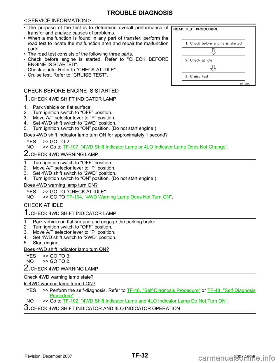
• The road test consists of the following three parts.
- Check before engine is started. Refer to "CHECK BEFORE
ENGINE IS STARTED".
- Check at idle. Refer to "CHECK AT IDLE" .
- Cruise test. Refer to "CRUISE TEST".
CHECK BEFORE ENGINE IS STARTED
1.CHECK 4WD SHIFT INDICATOR LAMP
1. Park vehicle on flat surface.
2. Turn ignition switch to “OFF” position.
3. Move A/T selector lever to “P” position.
4. Set 4WD shift switch to “2WD” position.
5. Turn ignition switch to “ON” position. (Do not start engine.)
Does 4WD shift indicator lamp turn ON for approximately 1 second?
YES >> GO TO 2.
NO >> Go to TF-107, "
4WD Shift Indicator Lamp or 4LO Indicator Lamp Does Not Change".
2.CHECK 4WD WARNING LAMP
1. Turn ignition switch to “OFF” position.
2. Move A/T selector lever to “P” position.
3. Set 4WD shift switch to “2WD” position.
4. Turn ignition switch to “ON” position. (Do not start engine.)
Does 4WD warning lamp turn ON?
YES >> GO TO "CHECK AT IDLE".
NO >> GO TO TF-104, "
4WD Warning Lamp Does Not Turn ON".
CHECK AT IDLE
1.CHECK 4WD SHIFT INDICATOR LAMP
1. Park vehicle on flat surface and engage the parking brake.
2. Turn ignition switch to “OFF” position.
3. Move A/T selector lever to “P” position.
4. Set 4WD shift switch to “2WD” position.
5. Start engine.
Does 4WD shift indicator lamp turn ON?
YES >> GO TO 3.
NO >> GO TO 2.
2.CHECK 4WD WARNING LAMP
Check 4WD warning lamp state?
Is 4WD warning lamp turned ON?
YES >> Perform the self-diagnosis. Refer to TF-48, "Self-Diagnosis Procedure" or TF-48, "Self-Diagnosis
Procedure".
NO >> Go to TF-102, "
4WD Shift Indicator Lamp and 4LO Indicator Lamp Do Not Turn ON".
3.CHECK 4WD SHIFT INDICATOR AND 4LO INDICATOR OPERATION
SMT089D