2007 INFINITI QX56 display
[x] Cancel search: displayPage 1075 of 3061
DI-64
< SERVICE INFORMATION >
REAR VIEW MONITOR
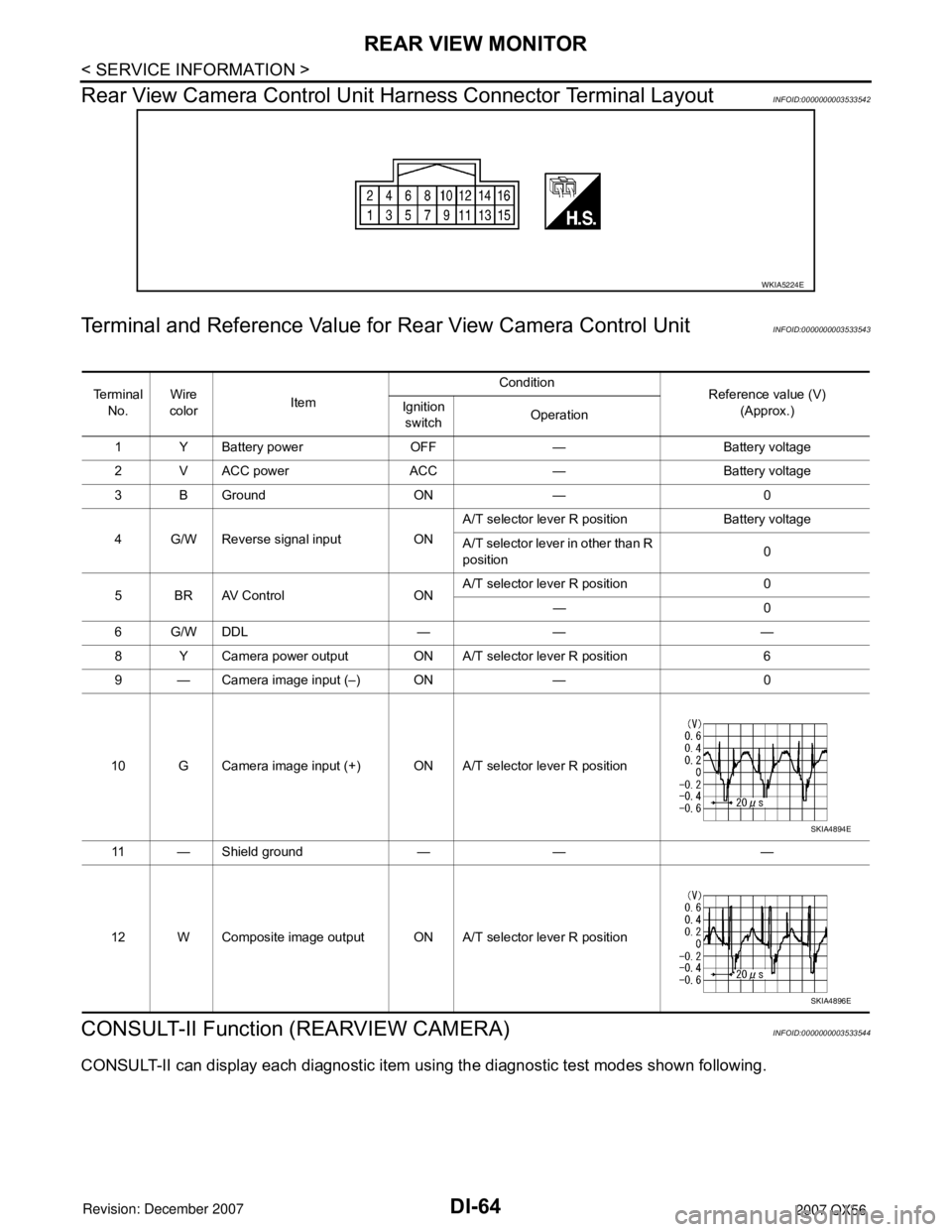
Rear View Camera Control Unit Harness Connector Terminal Layout
INFOID:0000000003533542
Terminal and Reference Value for Rear View Camera Control UnitINFOID:0000000003533543
CONSULT-II Function (REARVIEW CAMERA)INFOID:0000000003533544
CONSULT-II can display each diagnostic item using the diagnostic test modes shown following.
WKIA5224E
Te r m i n a l
No.Wire
colorItemCondition
Reference value (V)
(Approx.) Ignition
switchOperation
1 Y Battery power OFF — Battery voltage
2 V ACC power ACC — Battery voltage
3 B Ground ON — 0
4 G/W Reverse signal input ONA/T selector lever R position Battery voltage
A/T selector lever in other than R
position0
5BRAV Control ONA/T selector lever R position 0
—0
6G/WDDL — — —
8 Y Camera power output ON A/T selector lever R position 6
9 — Camera image input (–) ON — 0
10 G Camera image input (+) ON A/T selector lever R position
11 — Shield ground — — —
12 W Composite image output ON A/T selector lever R position
SKIA4894E
SKIA4896E
Page 1076 of 3061
REAR VIEW MONITOR
DI-65
< SERVICE INFORMATION >
C
D
E
F
G
H
I
J
L
MA
B
DI
N
O
P
CONSULT-II START PROCEDURE
Refer to GI-36, "CONSULT-II Start Procedure".
WORK SUPPORT
Refer to DI-65, "Side Distance Guideline Correction" for details.
DATA MONITOR
Display Item List
Side Distance Guideline CorrectionINFOID:0000000003533545
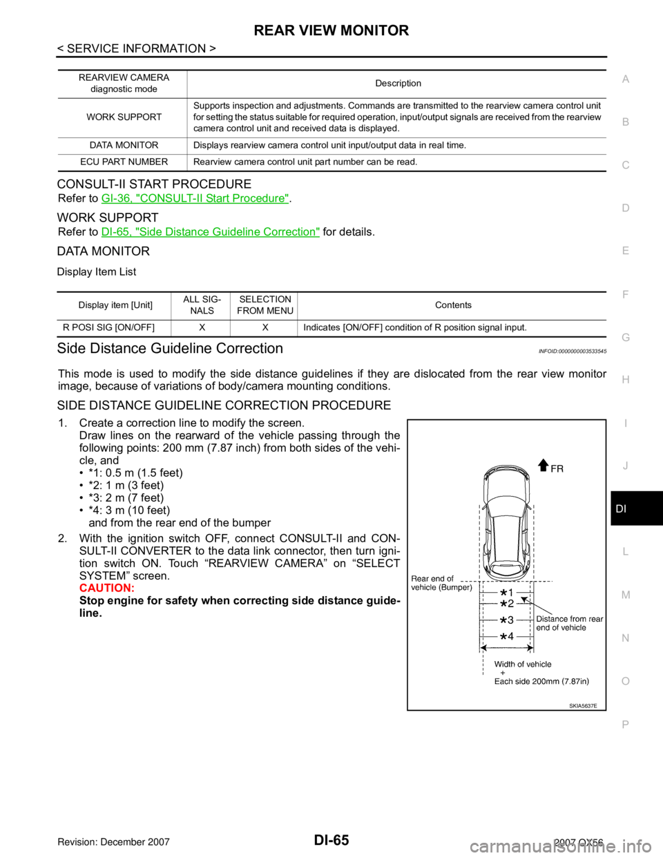
This mode is used to modify the side distance guidelines if they are dislocated from the rear view monitor
image, because of variations of body/camera mounting conditions.
SIDE DISTANCE GUIDELINE CORRECTION PROCEDURE
1. Create a correction line to modify the screen.
Draw lines on the rearward of the vehicle passing through the
following points: 200 mm (7.87 inch) from both sides of the vehi-
cle, and
• *1: 0.5 m (1.5 feet)
• *2: 1 m (3 feet)
• *3: 2 m (7 feet)
• *4: 3 m (10 feet)
and from the rear end of the bumper
2. With the ignition switch OFF, connect CONSULT-II and CON-
SULT-II CONVERTER to the data link connector, then turn igni-
tion switch ON. Touch “REARVIEW CAMERA” on “SELECT
SYSTEM” screen.
CAUTION:
Stop engine for safety when correcting side distance guide-
line.
REARVIEW CAMERA
diagnostic modeDescription
WORK SUPPORTSupports inspection and adjustments. Commands are transmitted to the rearview camera control unit
for setting the status suitable for required operation, input/output signals are received from the rearview
camera control unit and received data is displayed.
DATA MONITOR Displays rearview camera control unit input/output data in real time.
ECU PART NUMBER Rearview camera control unit part number can be read.
Display item [Unit]ALL SIG-
NALSSELECTION
FROM MENUContents
R POSI SIG [ON/OFF] X X Indicates [ON/OFF] condition of R position signal input.
SKIA5637E
Page 1078 of 3061
REAR VIEW MONITOR
DI-67
< SERVICE INFORMATION >
C
D
E
F
G
H
I
J
L
MA
B
DI
N
O
P
Power Supply and Ground Circuit InspectionINFOID:0000000003533546
1.CHECK FUSES
Check for blown rear view camera system fuses.
OK or NG
OK >> GO TO 2.
NG >> If fuse is blown, be sure to eliminate cause of problem before installing new fuse. Refer to PG-3
.
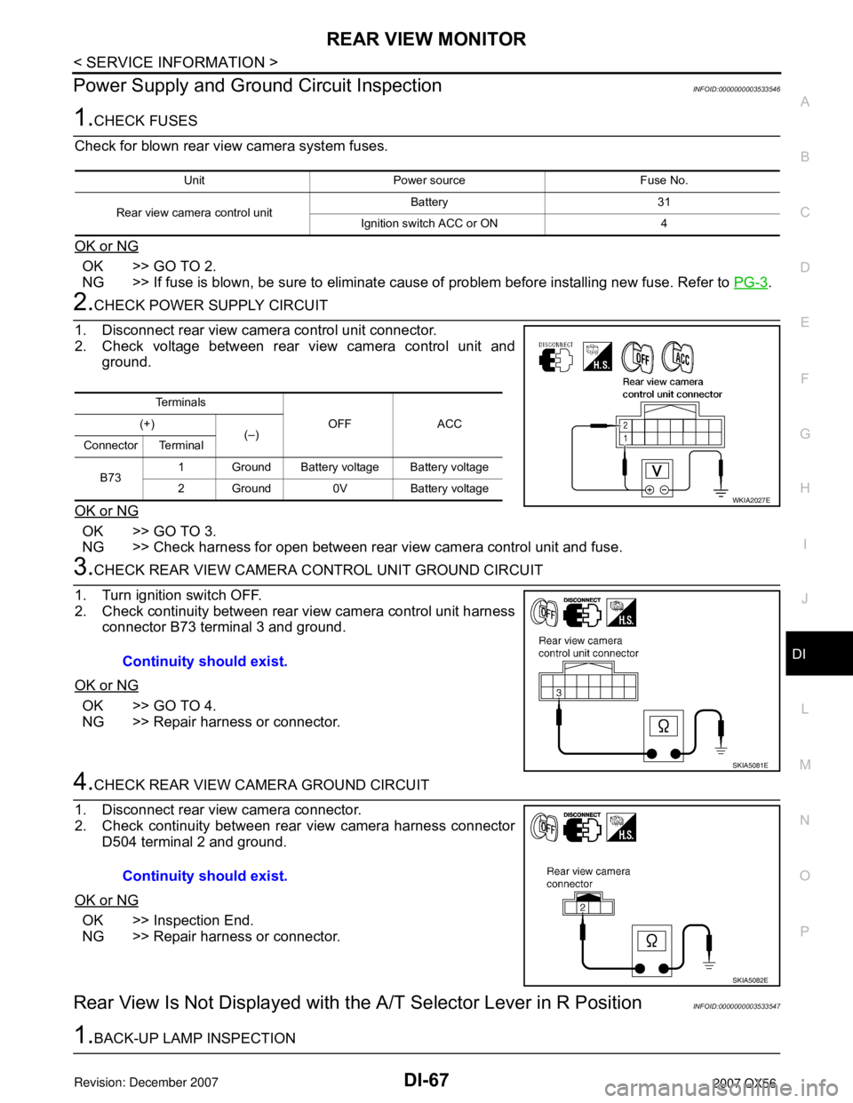
2.CHECK POWER SUPPLY CIRCUIT
1. Disconnect rear view camera control unit connector.
2. Check voltage between rear view camera control unit and
ground.
OK or NG
OK >> GO TO 3.
NG >> Check harness for open between rear view camera control unit and fuse.
3.CHECK REAR VIEW CAMERA CONTROL UNIT GROUND CIRCUIT
1. Turn ignition switch OFF.
2. Check continuity between rear view camera control unit harness
connector B73 terminal 3 and ground.
OK or NG
OK >> GO TO 4.
NG >> Repair harness or connector.
4.CHECK REAR VIEW CAMERA GROUND CIRCUIT
1. Disconnect rear view camera connector.
2. Check continuity between rear view camera harness connector
D504 terminal 2 and ground.
OK or NG
OK >> Inspection End.
NG >> Repair harness or connector.
Rear View Is Not Displayed with the A/T Selector Lever in R PositionINFOID:0000000003533547
1.BACK-UP LAMP INSPECTION
Unit Power source Fuse No.
Rear view camera control unitBattery 31
Ignition switch ACC or ON 4
Te r m i n a l s
OFF ACC (+)
(–)
Connector Terminal
B731 Ground Battery voltage Battery voltage
2 Ground 0V Battery voltage
WKIA2027E
Continuity should exist.
SKIA5081E
Continuity should exist.
SKIA5082E
Page 1079 of 3061

DI-68
< SERVICE INFORMATION >
REAR VIEW MONITOR
1. Turn ignition switch ON.
2. Shift A/T selector lever to R position.
Does back-up lamp illuminate?
YES >> GO TO 2.
NO >> Check back-up lamp system. Refer to LT- 8 0
.
2.CHECK REVERSE POSITION INPUT SIGNAL
With CONSULT-II
Select “DATA MONITOR” of “REARVIEW CAMERA”. Operate igni-
tion switch with “R POSI SIG” of “DATA MONITOR” and check oper-
ate status.
Without CONSULT-II
1. Turn ignition switch OFF.
2. Disconnect rear view camera control unit connector.
3. Turn ignition switch ON.
4. Shift A/T selector lever to R position.
5. Check voltage between rear view camera control unit harness
connector B73 terminal 4 and ground.
OK or NG
OK >> GO TO 3.
NG >> Check harness for open or short between rear view
camera control unit and back-up lamp relay.
3.CHECK DISPLAY CONTROL UNIT OUTPUT SIGNAL
1. Turn ignition switch OFF.
2. Disconnect rear view camera control unit connector.
3. Turn ignition switch ON.
4. Check voltage between rear view camera control unit harness
connector B73 terminal 5 and ground.
OK or NG
OK >> GO TO 5.
NG >> GO TO 4.
4.CHECK DISPLAY CONTROL UNIT CIRCUIT
SKIA7147E
Battery voltage should exist.
SKIA5086E
Voltage : Approx. 5V
SKIA7148E
Page 1080 of 3061
REAR VIEW MONITOR
DI-69
< SERVICE INFORMATION >
C
D
E
F
G
H
I
J
L
MA
B
DI
N
O
P
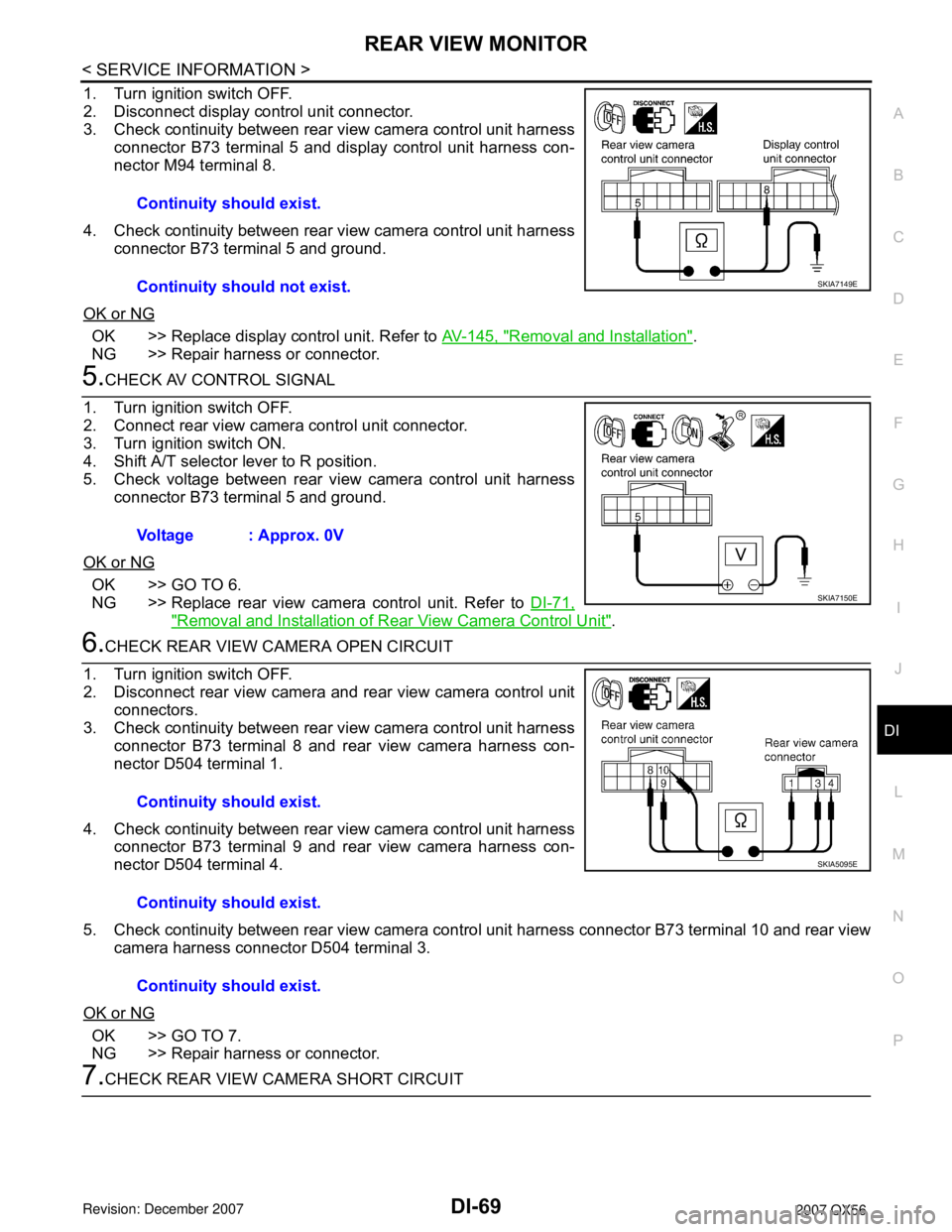
1. Turn ignition switch OFF.
2. Disconnect display control unit connector.
3. Check continuity between rear view camera control unit harness
connector B73 terminal 5 and display control unit harness con-
nector M94 terminal 8.
4. Check continuity between rear view camera control unit harness
connector B73 terminal 5 and ground.
OK or NG
OK >> Replace display control unit. Refer to AV-145, "Removal and Installation".
NG >> Repair harness or connector.
5.CHECK AV CONTROL SIGNAL
1. Turn ignition switch OFF.
2. Connect rear view camera control unit connector.
3. Turn ignition switch ON.
4. Shift A/T selector lever to R position.
5. Check voltage between rear view camera control unit harness
connector B73 terminal 5 and ground.
OK or NG
OK >> GO TO 6.
NG >> Replace rear view camera control unit. Refer to DI-71,
"Removal and Installation of Rear View Camera Control Unit".
6.CHECK REAR VIEW CAMERA OPEN CIRCUIT
1. Turn ignition switch OFF.
2. Disconnect rear view camera and rear view camera control unit
connectors.
3. Check continuity between rear view camera control unit harness
connector B73 terminal 8 and rear view camera harness con-
nector D504 terminal 1.
4. Check continuity between rear view camera control unit harness
connector B73 terminal 9 and rear view camera harness con-
nector D504 terminal 4.
5. Check continuity between rear view camera control unit harness connector B73 terminal 10 and rear view
camera harness connector D504 terminal 3.
OK or NG
OK >> GO TO 7.
NG >> Repair harness or connector.
7.CHECK REAR VIEW CAMERA SHORT CIRCUITContinuity should exist.
Continuity should not exist.
SKIA7149E
Voltage : Approx. 0V
SKIA7150E
Continuity should exist.
Continuity should exist.
Continuity should exist.
SKIA5095E
Page 1082 of 3061
REAR VIEW MONITOR
DI-71
< SERVICE INFORMATION >
C
D
E
F
G
H
I
J
L
MA
B
DI
N
O
P
1. Turn ignition switch OFF.
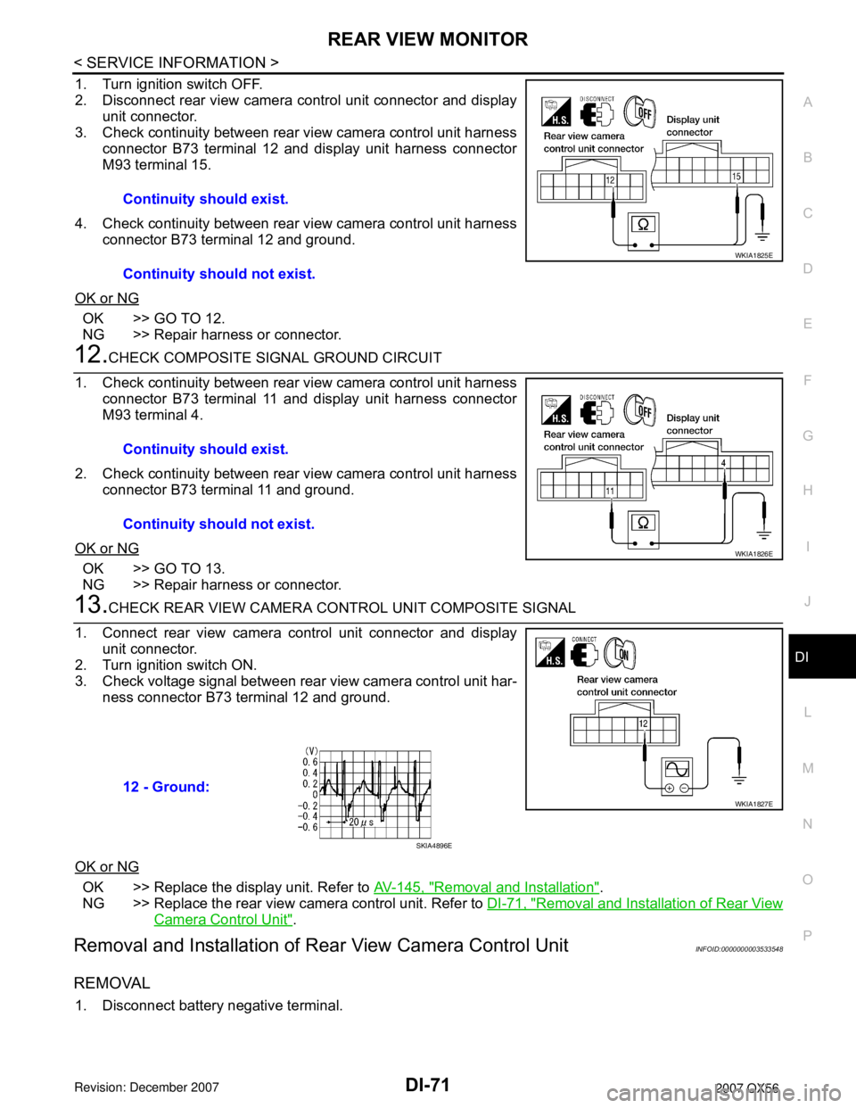
2. Disconnect rear view camera control unit connector and display
unit connector.
3. Check continuity between rear view camera control unit harness
connector B73 terminal 12 and display unit harness connector
M93 terminal 15.
4. Check continuity between rear view camera control unit harness
connector B73 terminal 12 and ground.
OK or NG
OK >> GO TO 12.
NG >> Repair harness or connector.
12.CHECK COMPOSITE SIGNAL GROUND CIRCUIT
1. Check continuity between rear view camera control unit harness
connector B73 terminal 11 and display unit harness connector
M93 terminal 4.
2. Check continuity between rear view camera control unit harness
connector B73 terminal 11 and ground.
OK or NG
OK >> GO TO 13.
NG >> Repair harness or connector.
13.CHECK REAR VIEW CAMERA CONTROL UNIT COMPOSITE SIGNAL
1. Connect rear view camera control unit connector and display
unit connector.
2. Turn ignition switch ON.
3. Check voltage signal between rear view camera control unit har-
ness connector B73 terminal 12 and ground.
OK or NG
OK >> Replace the display unit. Refer to AV-145, "Removal and Installation".
NG >> Replace the rear view camera control unit. Refer to DI-71, "
Removal and Installation of Rear View
Camera Control Unit".
Removal and Installation of Rear View Camera Control UnitINFOID:0000000003533548
REMOVAL
1. Disconnect battery negative terminal.Continuity should exist.
Continuity should not exist.
WKIA1825E
Continuity should exist.
Continuity should not exist.
WKIA1826E
12 - Ground:
WKIA1827E
SKIA4896E
Page 1092 of 3061
INDEX FOR DTC
EC-9
< SERVICE INFORMATION >
C
D
E
F
G
H
I
J
K
L
MA
EC
N
P O
SERVICE INFORMATION
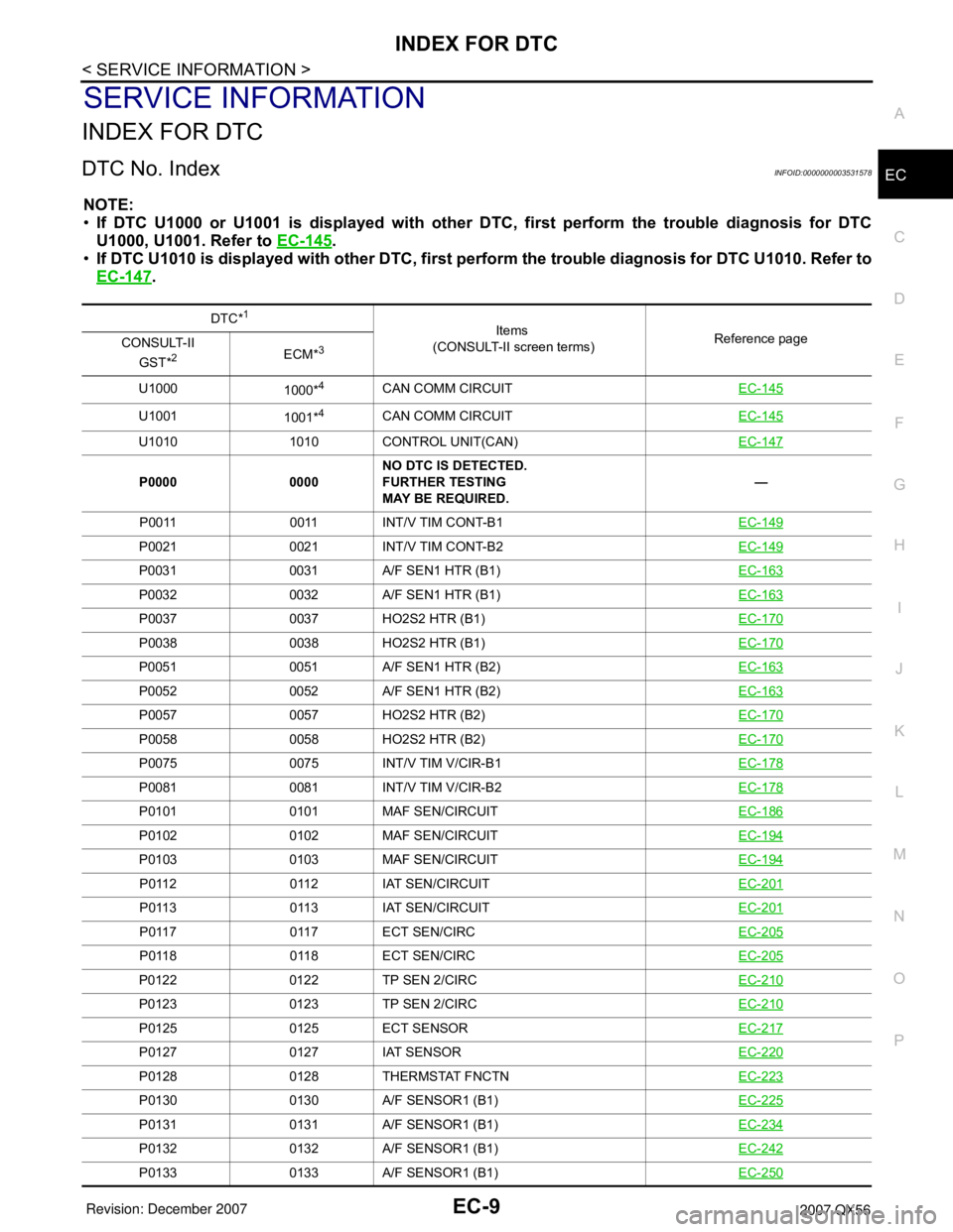
INDEX FOR DTC
DTC No. IndexINFOID:0000000003531578
NOTE:
•If DTC U1000 or U1001 is displayed with other DTC, first perform the trouble diagnosis for DTC
U1000, U1001. Refer to EC-145
.
•If DTC U1010 is displayed with other DTC, first perform the trouble diagnosis for DTC U1010. Refer to
EC-147
.
DTC*1
Items
(CONSULT-II screen terms)Reference page
CONSULT-II
GST*
2ECM*3
U1000
1000*4CAN COMM CIRCUITEC-145
U1001
1001*4CAN COMM CIRCUITEC-145
U1010 1010 CONTROL UNIT(CAN)EC-147
P0000 0000NO DTC IS DETECTED.
FURTHER TESTING
MAY BE REQUIRED.—
P0011 0011 INT/V TIM CONT-B1EC-149
P0021 0021 INT/V TIM CONT-B2EC-149
P0031 0031 A/F SEN1 HTR (B1)EC-163
P0032 0032 A/F SEN1 HTR (B1)EC-163
P0037 0037 HO2S2 HTR (B1)EC-170
P0038 0038 HO2S2 HTR (B1)EC-170
P0051 0051 A/F SEN1 HTR (B2)EC-163
P0052 0052 A/F SEN1 HTR (B2)EC-163
P0057 0057 HO2S2 HTR (B2)EC-170
P0058 0058 HO2S2 HTR (B2)EC-170
P0075 0075 INT/V TIM V/CIR-B1EC-178
P0081 0081 INT/V TIM V/CIR-B2EC-178
P0101 0101 MAF SEN/CIRCUITEC-186
P0102 0102 MAF SEN/CIRCUITEC-194
P0103 0103 MAF SEN/CIRCUITEC-194
P0112 0112 IAT SEN/CIRCUITEC-201
P0113 0113 IAT SEN/CIRCUITEC-201
P0117 0117 ECT SEN/CIRCEC-205
P0118 0118 ECT SEN/CIRCEC-205
P0122 0122 TP SEN 2/CIRCEC-210
P0123 0123 TP SEN 2/CIRCEC-210
P0125 0125 ECT SENSOREC-217
P0127 0127 IAT SENSOREC-220
P0128 0128 THERMSTAT FNCTNEC-223
P0130 0130 A/F SENSOR1 (B1)EC-225
P0131 0131 A/F SENSOR1 (B1)EC-234
P0132 0132 A/F SENSOR1 (B1)EC-242
P0133 0133 A/F SENSOR1 (B1)EC-250
Page 1095 of 3061
EC-12
< SERVICE INFORMATION >
INDEX FOR DTC
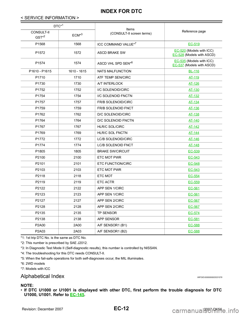
*1: 1st trip DTC No. is the same as DTC No.
*2: This number is prescribed by SAE J2012.
*3: In Diagnostic Test Mode II (Self-diagnostic results), this number is controlled by NISSAN.
*4: The troubleshooting for this DTC needs CONSULT-II.
*5: When the fail-safe operations for both self-diagnoses occur, the MIL illuminates.
*6: 2WD models
*7: Models with ICC
Alphabetical IndexINFOID:0000000003531579
NOTE:
•If DTC U1000 or U1001 is displayed with other DTC, first perform the trouble diagnosis for DTC
U1000, U1001. Refer to EC-145
.
P1568 1568
ICC COMMAND VALUE*7EC-519
P1572 1572 ASCD BRAKE SWEC-520 (Models with ICC)
EC-528
(Models with ASCD)
P1574 1574
ASCD VHL SPD SEN*
6EC-535 (Models with ICC)
EC-537
(Models with ASCD)
P1610 - P1615 1610 - 1615 NATS MALFUNCTIONBL-116
P1710 1710 ATF TEMP SEN/CIRCAT- 11 9
P1730 1730 A/T INTERLOCKAT- 1 2 6
P1752 1752 I/C SOLENOID/CIRCAT- 1 3 0
P1754 1754 I/C SOLENOID FNCTNAT- 1 3 2
P1757 1757 FR/B SOLENOID/CIRCAT- 1 3 4
P1759 1759 FR/B SOLENOID FNCTAT- 1 3 6
P1762 1762 D/C SOLENOID/CIRCAT- 1 3 8
P1764 1764 D/C SOLENOID FNCTNAT- 1 4 0
P1767 1767 HLR/C SOL/CIRCAT- 1 4 2
P1769 1769 HLR/C SOL FNCTNAT- 1 4 4
P1772 1772 LC/B SOLENOID/CIRCAT- 1 4 6
P1774 1774 LC/B SOLENOID FNCTAT- 1 4 8
P1805 1805 BRAKE SW/CIRCUITEC-539
P2100 2100 ETC MOT PWREC-543
P2101 2101 ETC FUNCTION/CIRCEC-548
P2103 2103 ETC MOT PWREC-543
P2118 2118 ETC MOTEC-554
P2119 2119 ETC ACTREC-559
P2122 2122 APP SEN 1/CIRCEC-561
P2123 2123 APP SEN 1/CIRCEC-561
P2127 2127 APP SEN 2/CIRCEC-567
P2128 2128 APP SEN 2/CIRCEC-567
P2135 2135 TP SENSOREC-574
P2138 2138 APP SENSOREC-581
P2A00 2A00 A/F SENSOR1 (B1)EC-588
P2A03 2A03 A/F SENSOR1 (B2)EC-588
DTC*1
Items
(CONSULT-II screen terms)Reference page
CONSULT-II
GST*
2ECM*3