Page 2936 of 3061
TF-114
< SERVICE INFORMATION >
TROUBLE DIAGNOSIS FOR SYMPTOMS
OK >> GO TO 7.
NG >> Check transfer control unit pin terminals for damage or loose connection with harness connector.
If any items are damaged, repair or replace damaged parts.
7.CHECK TRANSFER INNER PARTS
1. Disassemble transfer assembly. Refer to TF-128, "
Disassembly and Assembly".
2. Check transfer inner parts.
OK or NG
OK >> Inspection End.
NG >> Repair or replace damaged parts.
4WD System Does Not OperateINFOID:0000000003532561
SYMPTOM:
The vehicle cannot be put into 4WD mode. (Hydraulic system failure)
DIAGNOSTIC PROCEDURE
1.CHECK SYSTEM FOR 4WD SHIFT SWITCH
Perform trouble diagnosis for 4WD shift switch system. Refer to TF-57, "
4WD Shift Switch".
OK or NG
OK >> GO TO 2.
NG >> Repair or replace damaged parts.
2.CHECK SYSTEM FOR CLUTCH PRESSURE SWITCH
Perform trouble diagnosis for clutch pressure switch system. Refer to TF-92, "
Clutch Pressure Switch".
OK or NG
OK >> GO TO 3.
NG >> Repair or replace damaged parts.
3.SYMPTOM CHECK
Check again.
OK or NG
OK >> Inspection End.
NG >> GO TO 4.
4.CHECK TRANSFER CONTROL UNIT
Check transfer control unit input/output signal. Refer to TF-35, "
Transfer Control Unit Input/Output Signal Ref-
erence Value".
OK or NG
OK >> GO TO 5.
NG >> Check transfer control unit pin terminals for damage or loose connection with harness connector.
If any items are damaged, repair or replace damaged parts.
5.CHECK TRANSFER INNER PARTS
1. Disassemble transfer assembly. Refer to TF-128, "
Disassembly and Assembly".
2. Check transfer inner parts.
OK or NG
OK >> Inspection End.
NG >> Repair or replace damaged parts.
Page 2951 of 3061
TRANSFER ASSEMBLY
TF-129
< SERVICE INFORMATION >
C
E
F
G
H
I
J
K
L
MA
B
TF
N
O
P
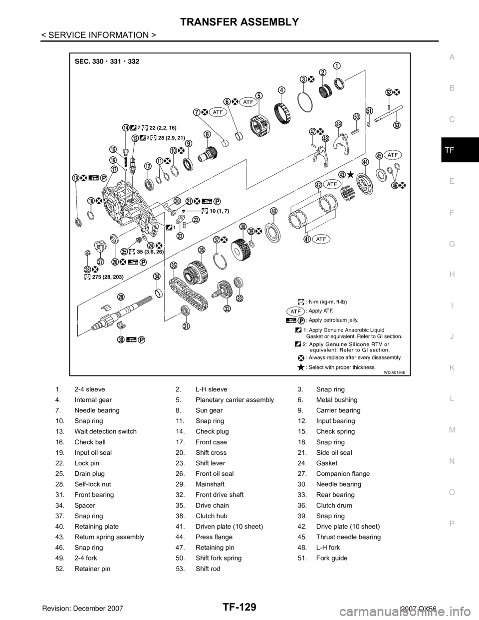
1. 2-4 sleeve 2. L-H sleeve 3. Snap ring
4. Internal gear 5. Planetary carrier assembly 6. Metal bushing
7. Needle bearing 8. Sun gear 9. Carrier bearing
10. Snap ring 11. Snap ring 12. Input bearing
13. Wait detection switch 14. Check plug 15. Check spring
16. Check ball 17. Front case 18. Snap ring
19. Input oil seal 20. Shift cross 21. Side oil seal
22. Lock pin 23. Shift lever 24. Gasket
25. Drain plug 26. Front oil seal 27. Companion flange
28. Self-lock nut 29. Mainshaft 30. Needle bearing
31. Front bearing 32. Front drive shaft 33. Rear bearing
34. Spacer 35. Drive chain 36. Clutch drum
37. Snap ring 38. Clutch hub 39. Snap ring
40. Retaining plate 41. Driven plate (10 sheet) 42. Drive plate (10 sheet)
43. Return spring assembly 44. Press flange 45. Thrust needle bearing
46. Snap ring 47. Retaining pin 48. L-H fork
49. 2-4 fork 50. Shift fork spring 51. Fork guide
52. Retainer pin 53. Shift rod
WDIA0194E
Page 2952 of 3061
TF-130
< SERVICE INFORMATION >
TRANSFER ASSEMBLY
DISASSEMBLY
Rear Case
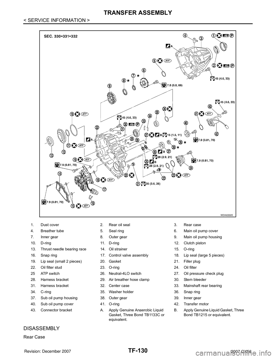
1. Dust cover 2. Rear oil seal 3. Rear case
4. Breather tube 5. Seal ring 6. Main oil pump cover
7. Inner gear 8. Outer gear 9. Main oil pump housing
10. D-ring 11. D-ring 12. Clutch piston
13. Thrust needle bearing race 14. Oil strainer 15. O-ring
16. Snap ring 17. Control valve assembly 18. Lip seal (large 5 pieces)
19. Lip seal (small 2 pieces) 20. Gasket 21. Filler plug
22. Oil filter stud 23. O-ring 24. Oil filter
25 ATP switch 26. Neutral-4LO switch 27. Oil pressure check plug
28. Harness bracket 29. Air breather hose clamp 30. Stem bleeder
31. Harness bracket 32. Center case 33. Mainshaft rear bearing
34. C-ring 35. Washer holder 36. Snap ring
37. Sub oil pump housing 38. Outer gear 39. Inner gear
40. Sub oil pump cover 41. O-ring 42. Transfer motor
43. Connector bracket A. Apply Genuine Anaerobic Liquid
Gasket, Three Bond TB1133C or
equivalent.B. Apply Genuine Liquid Gasket, Three
Bond TB1215 or equivalent.
WDIA0302E
Page 2962 of 3061
TF-140
< SERVICE INFORMATION >
TRANSFER ASSEMBLY
17. Remove the snap ring from the mainshaft using suitable tool.
18. Remove the press flange from the mainshaft.
19. Remove the return spring assembly from the clutch hub.
20. Remove each plate from the clutch drum.
21. Remove the snap ring from the mainshaft.
SDIA2112E
SMT910C
SMT911C
SMT912C
SDIA2113E
Page 2963 of 3061
TRANSFER ASSEMBLY
TF-141
< SERVICE INFORMATION >
C
E
F
G
H
I
J
K
L
MA
B
TF
N
O
P
22. Remove the mainshaft from the clutch drum and clutch hub
using suitable tool.
23. Remove the needle bearing and spacer from the mainshaft.
24. Remove the snap ring from the clutch hub using suitable tool.
25. Remove the oil pressure check plug from the oil pressure check
port.
26. Apply air gradually from the oil pressure check port, and remove
the clutch piston assembly from the center case.
27. Remove the thrust needle bearing race from the clutch piston by
hooking a edge into 3 notches of the thrust needle bearing race
using suitable tool.
CAUTION:
Do not damage clutch piston or thrust needle bearing race.
SMT914C
WDIA0101E
SDIA3188E
SDIA2116E
SDIA2118E
Page 2964 of 3061
TF-142
< SERVICE INFORMATION >
TRANSFER ASSEMBLY
28. Remove the two D-rings from the clutch piston.
29. Remove the mainshaft rear bearing from the center case using
Tool.
30. Remove the two bolts and oil strainer.
31. Remove the two O-rings from the oil strainer.
32. Remove the snap ring. Then push the connector assembly into
the center case to remove the control valve assembly.
SDIA2781E
Tool number : KV38100300 (J-25523)
SDIA2129E
SDIA2119E
SDIA2782E
SDIA2122E
Page 2965 of 3061
TRANSFER ASSEMBLY
TF-143
< SERVICE INFORMATION >
C
E
F
G
H
I
J
K
L
MA
B
TF
N
O
P
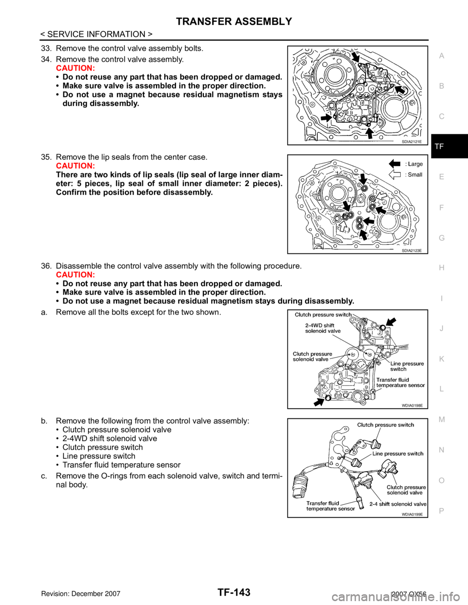
33. Remove the control valve assembly bolts.
34. Remove the control valve assembly.
CAUTION:
• Do not reuse any part that has been dropped or damaged.
• Make sure valve is assembled in the proper direction.
• Do not use a magnet because residual magnetism stays
during disassembly.
35. Remove the lip seals from the center case.
CAUTION:
There are two kinds of lip seals (lip seal of large inner diam-
eter: 5 pieces, lip seal of small inner diameter: 2 pieces).
Confirm the position before disassembly.
36. Disassemble the control valve assembly with the following procedure.
CAUTION:
• Do not reuse any part that has been dropped or damaged.
• Make sure valve is assembled in the proper direction.
• Do not use a magnet because residual magnetism stays during disassembly.
a. Remove all the bolts except for the two shown.
b. Remove the following from the control valve assembly:
• Clutch pressure solenoid valve
• 2-4WD shift solenoid valve
• Clutch pressure switch
• Line pressure switch
• Transfer fluid temperature sensor
c. Remove the O-rings from each solenoid valve, switch and termi-
nal body.
SDIA2121E
SDIA2123E
WDIA0198E
WDIA0199E
Page 2969 of 3061
TRANSFER ASSEMBLY
TF-147
< SERVICE INFORMATION >
C
E
F
G
H
I
J
K
L
MA
B
TF
N
O
P
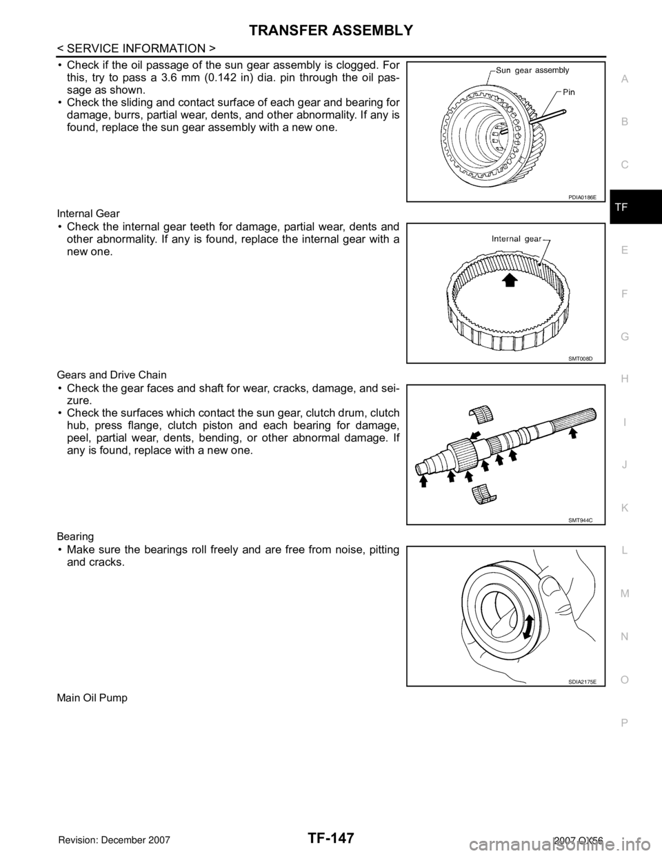
• Check if the oil passage of the sun gear assembly is clogged. For
this, try to pass a 3.6 mm (0.142 in) dia. pin through the oil pas-
sage as shown.
• Check the sliding and contact surface of each gear and bearing for
damage, burrs, partial wear, dents, and other abnormality. If any is
found, replace the sun gear assembly with a new one.
Internal Gear
• Check the internal gear teeth for damage, partial wear, dents and
other abnormality. If any is found, replace the internal gear with a
new one.
Gears and Drive Chain
• Check the gear faces and shaft for wear, cracks, damage, and sei-
zure.
• Check the surfaces which contact the sun gear, clutch drum, clutch
hub, press flange, clutch piston and each bearing for damage,
peel, partial wear, dents, bending, or other abnormal damage. If
any is found, replace with a new one.
Bearing
• Make sure the bearings roll freely and are free from noise, pitting
and cracks.
Main Oil Pump
PDIA0186E
SMT008D
SMT944C
SDIA2175E