2007 INFINITI QX56 clutch
[x] Cancel search: clutchPage 2423 of 3061
IPDM E/R (INTELLIGENT POWER DISTRIBUTION MODULE ENGINE ROOM)
PG-21
< SERVICE INFORMATION >
C
D
E
F
G
H
I
J
L
MA
B
PG
N
O
P
CAUTION:
Be sure to perform BL-25, "
Door Switch Check" when the auto active test cannot be performed.
INSPECTION IN AUTO ACTIVE TEST MODE
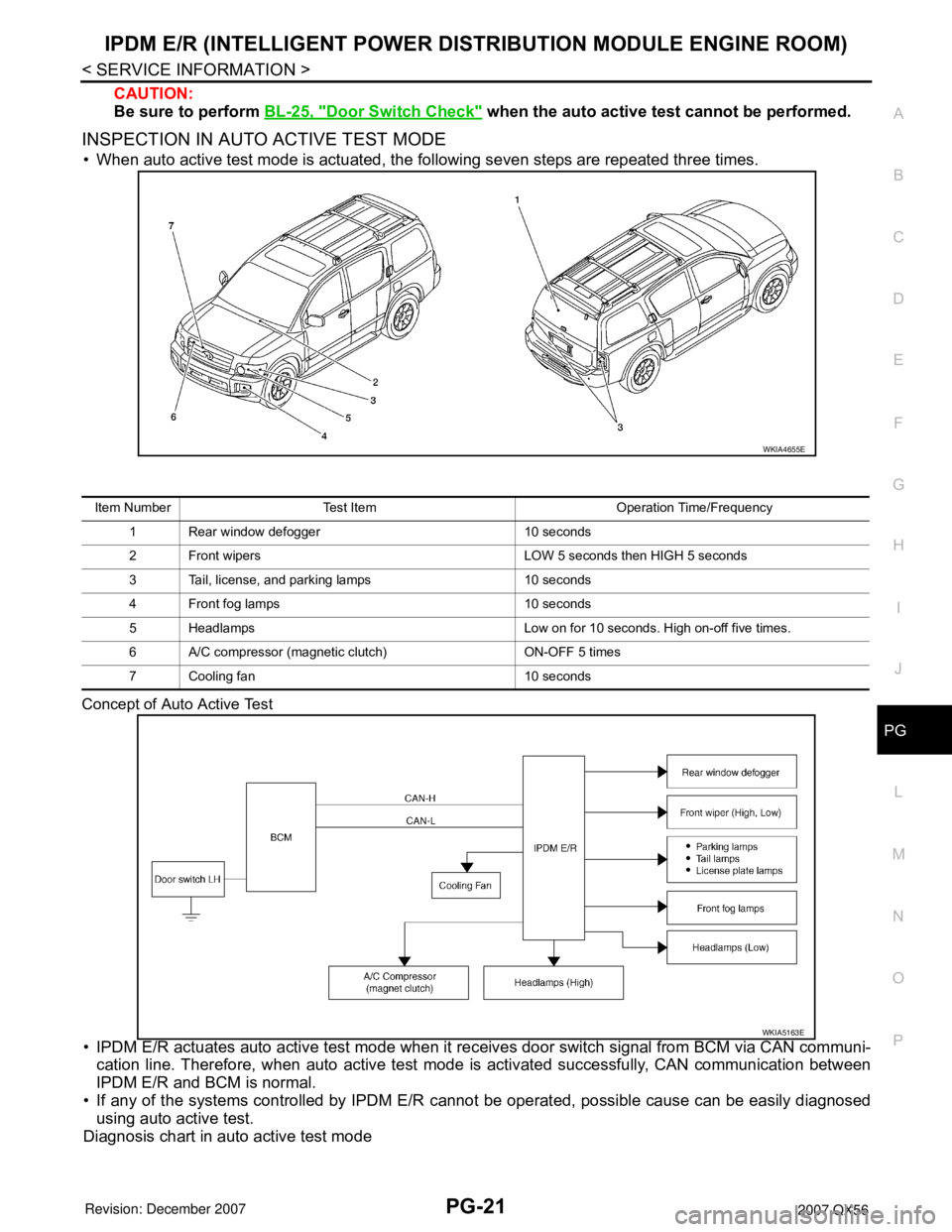
• When auto active test mode is actuated, the following seven steps are repeated three times.
Concept of Auto Active Test
• IPDM E/R actuates auto active test mode when it receives door switch signal from BCM via CAN communi-
cation line. Therefore, when auto active test mode is activated successfully, CAN communication between
IPDM E/R and BCM is normal.
• If any of the systems controlled by IPDM E/R cannot be operated, possible cause can be easily diagnosed
using auto active test.
Diagnosis chart in auto active test mode
WKIA4655E
Item Number Test Item Operation Time/Frequency
1 Rear window defogger 10 seconds
2 Front wipers LOW 5 seconds then HIGH 5 seconds
3 Tail, license, and parking lamps 10 seconds
4 Front fog lamps 10 seconds
5 Headlamps Low on for 10 seconds. High on-off five times.
6 A/C compressor (magnetic clutch) ON-OFF 5 times
7 Cooling fan 10 seconds
WKIA5163E
Page 2424 of 3061

PG-22
< SERVICE INFORMATION >
IPDM E/R (INTELLIGENT POWER DISTRIBUTION MODULE ENGINE ROOM)
Terminal and Reference Value for IPDM E/R
INFOID:0000000003533840
Symptom Inspection contents Possible cause
Rear window defogger
does not operate.Perform auto active
test. Does rear win-
dow defogger oper-
ate?YES • BCM signal input circuit
NO• Rear window defogger relay
• Open circuit of rear window defogger
•IPDM E/R malfunction
• Harness or connector malfunction between IPDM E/R and rear window
defogger
Any of front wipers, tail
and parking lamps, front
fog lamps, and head-
lamps (Hi, Lo) do not op-
erate.Perform auto active
test. Does system in
question operate?YES • BCM signal input system
NO• Lamp/wiper motor malfunction
• Lamp/wiper motor ground circuit malfunction
• Harness/connector malfunction between IPDM E/R and system in ques-
tion
• IPDM E/R (integrated relay) malfunction
A/C compressor does
not operate.Perform auto active
test. Does magnet
clutch operate?YES• BCM signal input circuit
• CAN communication signal between BCM and ECM
• CAN communication signal between ECM and IPDM E/R
NO• Magnet clutch malfunction
• Harness/connector malfunction between IPDM E/R and magnet clutch
• IPDM E/R (integrated relay) malfunction
Cooling fan does not op-
erate.Perform auto active
test. Does cooling fan
operate?YES• ECM signal input circuit
• CAN communication signal between ECM and IPDM E/R
NO• Cooling fan motor malfunction
• Harness/connector malfunction between IPDM E/R and cooling fan mo-
tor
• IPDM E/R (integrated relay) malfunction
Te r m i n a lWire
colorSignal nameSignal
input/
outputMeasuring condition
Reference value
(Approx.) Igni-
tion
switchOperation or condition
1 B/Y Battery power supply Input OFF — Battery voltage
2 R Battery power supply Input OFF — Battery voltage
3 BR ECM relay Output —Ignition switch ON or START Battery voltage
Ignition switch OFF or ACC 0V
4 W/L ECM relay Output —Ignition switch ON or START Battery voltage
Ignition switch OFF or ACC 0V
6LThrottle control motor
relayOutput —Ignition switch ON or START Battery voltage
Ignition switch OFF or ACC 0V
7 W/B ECM relay control Input —Ignition switch ON or START 0V
Ignition switch OFF or ACC Battery voltage
8 R/B Fuse 54 Output —Ignition switch ON or START Battery voltage
Ignition switch OFF or ACC 0V
10 GDaytime light relay
controlOutput ONDaytime light system active 0V
Daytime light system inactive Battery voltage
11 Y/B A/C compressor OutputON or
STARTA/C switch ON or defrost A/C
switchBattery voltage
A/C switch OFF or defrost A/C
switch0V
Page 2537 of 3061
SQUEAK AND RATTLE TROUBLE DIAGNOSIS
RF-5
< SERVICE INFORMATION >
C
D
E
F
G
H
J
K
L
MA
B
RF
N
O
P
If the noise can be duplicated easily during the test drive, to help identify the source of the noise, try to dupli-
cate the noise with the vehicle stopped by doing one or all of the following:
1) Close a door.
2) Tap or push/pull around the area where the noise appears to be coming from.
3) Rev the engine.
4) Use a floor jack to recreate vehicle "twist".
5) At idle, apply engine load (electrical load, half-clutch on M/T model, drive position on A/T model).
6) Raise the vehicle on a hoist and hit a tire with a rubber hammer.
• Drive the vehicle and attempt to duplicate the conditions the customer states exist when the noise occurs.
• If it is difficult to duplicate the noise, drive the vehicle slowly on an undulating or rough road to stress the
vehicle body.
CHECK RELATED SERVICE BULLETINS
After verifying the customer concern or symptom, check ASIST for Technical Service Bulletins (TSBs) related
to that concern or symptom.
If a TSB relates to the symptom, follow the procedure to repair the noise.
LOCATE THE NOISE AND IDENTIFY THE ROOT CAUSE
1. Narrow down the noise to a general area. To help pinpoint the source of the noise, use a listening tool
(Chassis Ear: J-39570, Engine Ear: J-39565 and mechanic's stethoscope).
2. Narrow down the noise to a more specific area and identify the cause of the noise by:
• Removing the components in the area that you suspect the noise is coming from.
Do not use too much force when removing clips and fasteners, otherwise clips and fastener can be broken
or lost during the repair, resulting in the creation of new noise.
• Tapping or pushing/pulling the component that you suspect is causing the noise.
Do not tap or push/pull the component with excessive force, otherwise the noise will be eliminated only tem-
porarily.
• Feeling for a vibration with your hand by touching the component(s) that you suspect is (are) causing the
noise.
• Placing a piece of paper between components that you suspect are causing the noise.
• Looking for loose components and contact marks.
Refer to RF-6, "
Generic Squeak and Rattle Troubleshooting" .
REPAIR THE CAUSE
• If the cause is a loose component, tighten the component securely.
• If the cause is insufficient clearance between components:
- Separate components by repositioning or loosening and retightening the component, if possible.
- Insulate components with a suitable insulator such as urethane pads, foam blocks, felt cloth tape or ure-
thane tape. A NISSAN Squeak and Rattle Kit (J-43980) is available through your authorized NISSAN Parts
Department.
CAUTION:
Do not use excessive force as many components are constructed of plastic and may be damaged.
Always check with the Parts Department for the latest parts information.
The following materials are contained in the NISSAN Squeak and Rattle Kit (J-43980). Each item can be
ordered separately as needed.
URETHANE PADS [1.5 mm (0.059 in) thick]
Insulates connectors, harness, etc.
76268-9E005: 100×135 mm (3.94×5.31 in)
76884-71L01: 60×85 mm (2.36×3.35 in)
76884-71L02: 15×25 mm (0.59×0.98 in)
INSULATOR (Foam blocks)
Insulates components from contact. Can be used to fill space behind a panel.
73982-9E000: 45 mm (1.77 in) thick, 50×50 mm (1.97×1.97 in)
73982-50Y00: 10 mm (0.39 in) thick, 50×50 mm (1.97×1.97 in)
INSULATOR (Light foam block)
80845-71L00: 30 mm (1.18 in) thick, 30×50 mm (1.18×1.97 in)
FELT CLOTH TAPE
Used to insulate where movement does not occur. Ideal for instrument panel applications.
68370-4B000: 15×25 mm (0.59×0.98 in) pad/68239-13E00: 5 mm (0.20 in) wide tape roll.
The following materials, not found in the kit, can also be used to repair squeaks and rattles.
UHMW (TEFLON) TAPE
Page 2678 of 3061
SE-6
< SERVICE INFORMATION >
SQUEAK AND RATTLE TROUBLE DIAGNOSIS
If the noise can be duplicated easily during the test drive, to help identify the source of the noise, try to dupli-
cate the noise with the vehicle stopped by doing one or all of the following:
1) Close a door.
2) Tap or push/pull around the area where the noise appears to be coming from.
3) Rev the engine.
4) Use a floor jack to recreate vehicle “twist”.
5) At idle, apply engine load (electrical load, half-clutch on M/T model, drive position on A/T model).
6) Raise the vehicle on a hoist and hit a tire with a rubber hammer.
• Drive the vehicle and attempt to duplicate the conditions the customer states exist when the noise occurs.
• If it is difficult to duplicate the noise, drive the vehicle slowly on an undulating or rough road to stress the
vehicle body.
CHECK RELATED SERVICE BULLETINS
After verifying the customer concern or symptom, check ASIST for Technical Service Bulletins (TSBs) related
to that concern or symptom.
If a TSB relates to the symptom, follow the procedure to repair the noise.
LOCATE THE NOISE AND IDENTIFY THE ROOT CAUSE
1. Narrow down the noise to a general area.To help pinpoint the source of the noise, use a listening tool
(Chassis Ear: J-39570, Engine Ear: J-39565 and mechanic's stethoscope).
2. Narrow down the noise to a more specific area and identify the cause of the noise by:
• removing the components in the area that you suspect the noise is coming from.
Do not use too much force when removing clips and fasteners, otherwise clips and fasteners can be broken
or lost during the repair, resulting in the creation of new noise.
• tapping or pushing/pulling the component that you suspect is causing the noise.
Do not tap or push/pull the component with excessive force, otherwise the noise will be eliminated only tem-
porarily.
• feeling for a vibration with your hand by touching the component(s) that you suspect is (are) causing the
noise.
• placing a piece of paper between components that you suspect are causing the noise.
• looking for loose components and contact marks.
Refer to SE-7, "
Generic Squeak and Rattle Troubleshooting" .
REPAIR THE CAUSE
• If the cause is a loose component, tighten the component securely.
• If the cause is insufficient clearance between components:
- separate components by repositioning or loosening and retightening the component, if possible.
- insulate components with a suitable insulator such as urethane pads, foam blocks, felt cloth tape or urethane
tape. A NISSAN Squeak and Rattle Kit (J-43980) is available through your authorized NISSAN Parts Depart-
ment.
CAUTION:
Do not use excessive force as many components are constructed of plastic and may be damaged.
Always check with the Parts Department for the latest parts information.
The following materials are contained in the NISSAN Squeak and Rattle Kit (J-43980). Each item can be
ordered separately as needed.
URETHANE PADS [1.5 mm (0.059 in) thick]
Insulates connectors, harness, etc.
76268-9E005: 100×135 mm (3.94×5.31 in)/76884-71L01: 60×85 mm (2.36×3.35 in)/76884-71L02: 15×25
mm (0.59×0.98 in)
INSULATOR (Foam blocks)
Insulates components from contact. Can be used to fill space behind a panel.
73982-9E000: 45 mm (1.77 in) thick, 50×50 mm (1.97×1.97 in)/73982-50Y00: 10 mm (0.39 in) thick,
50×50 mm (1.97×1.97 in)
INSULATOR (Light foam block)
80845-71L00: 30 mm (1.18 in) thick, 30×50 mm (1.18×1.97 in)
FELT CLOTH TAPE
Used to insulate where movement does not occur. Ideal for instrument panel applications.
68370-4B000: 15×25 mm (0.59×0.98 in) pad/68239-13E00: 5 mm (0.20 in) wide tape roll. The following
materials not found in the kit can also be used to repair squeaks and rattles.
UHMW (TEFLON) TAPE
Insulates where slight movement is present. Ideal for instrument panel applications.
Page 2823 of 3061

TF-1
DRIVELINE/AXLE
C
E
F
G
H
I
J
K
L
M
SECTION TF
A
B
TF
N
O
P
CONTENTS
TRANSFER
SERVICE INFORMATION ............................3
PRECAUTIONS ...................................................3
Precaution for Supplemental Restraint System
(SRS) "AIR BAG" and "SEAT BELT PRE-TEN-
SIONER" ...................................................................
3
Precaution for Transfer Assembly and Transfer
Control Unit Replacement .........................................
3
Precaution .................................................................4
Service Notice ...........................................................4
PREPARATION ...................................................6
Special Service Tool .................................................6
Commercial Service Tool ..........................................9
NOISE, VIBRATION AND HARSHNESS
(NVH) TROUBLESHOOTING ............................
10
NVH Troubleshooting Chart ....................................10
TRANSFER FLUID .............................................11
Replacement ...........................................................11
Inspection ................................................................11
ALL-MODE 4WD SYSTEM ................................12
Cross-Sectional View ..............................................12
Power Transfer ........................................................12
System Description .................................................14
Schematic ...............................................................19
CAN Communication ...............................................20
TROUBLE DIAGNOSIS .....................................21
How to Perform Trouble Diagnosis .........................21
Location of Electrical Parts ......................................22
Circuit Diagram .......................................................23
Wiring Diagram - T/F - .............................................24
Inspections Before Trouble Diagnosis ....................31
Trouble Diagnosis Chart by Symptom ....................34
Transfer Control Unit Input/Output Signal Refer-
ence Value ..............................................................
35
CONSULT-II Function (ALL MODE AWD/4WD) .....42
Self-Diagnosis Procedure .......................................48
TROUBLE DIAGNOSIS FOR SYSTEM ............51
Power Supply Circuit for Transfer Control Unit ........51
Transfer Control Unit ...............................................53
Output Shaft Revolution Signal (TCM) ....................53
Vehicle Speed Sensor (ABS) ..................................54
Neutral-4LO Switch .................................................54
4WD Shift Switch .....................................................57
Wait Detection Switch ..............................................60
PNP Switch Signal (TCM) .......................................63
Actuator Motor .........................................................64
Actuator Position Switch ..........................................69
Transfer Control Device ...........................................72
Engine Speed Signal (ECM) ....................................76
Clutch Pressure Solenoid ........................................76
2-4WD Solenoid ......................................................80
Transfer Motor .........................................................84
Transfer Fluid Temperature .....................................90
Clutch Pressure Switch ...........................................92
Line Pressure Switch ...............................................94
Throttle Position Signal (ECM) ................................97
ABS Operation Signal (ABS) ...................................97
VDC Operation Signal (ABS) ...................................98
TCS Operation Signal (ABS) ...................................98
CAN Communication Line .......................................99
ATP Switch ..............................................................99
TROUBLE DIAGNOSIS FOR SYMPTOMS ....102
4WD Shift Indicator Lamp and 4LO Indicator
Lamp Do Not Turn ON ...........................................
102
4WD Warning Lamp Does Not Turn ON ...............104
4WD Shift Indicator Lamp or 4LO Indicator Lamp
Does Not Change ..................................................
107
ATP Warning Lamp Turns ON ...............................109
4LO Indicator Lamp Repeats Flashing ..................110
4WD Warning Lamp Flashes Rapidly ....................111
4WD Warning Lamp Flashes Slowly .....................112
Heavy Tight-corner Braking Symptom Occurs ......113
4WD System Does Not Operate ............................114
TRANSFER CONTROL UNIT .........................115
Removal and Installation .......................................115
Page 2834 of 3061
TF-12
< SERVICE INFORMATION >
ALL-MODE 4WD SYSTEM
ALL-MODE 4WD SYSTEM
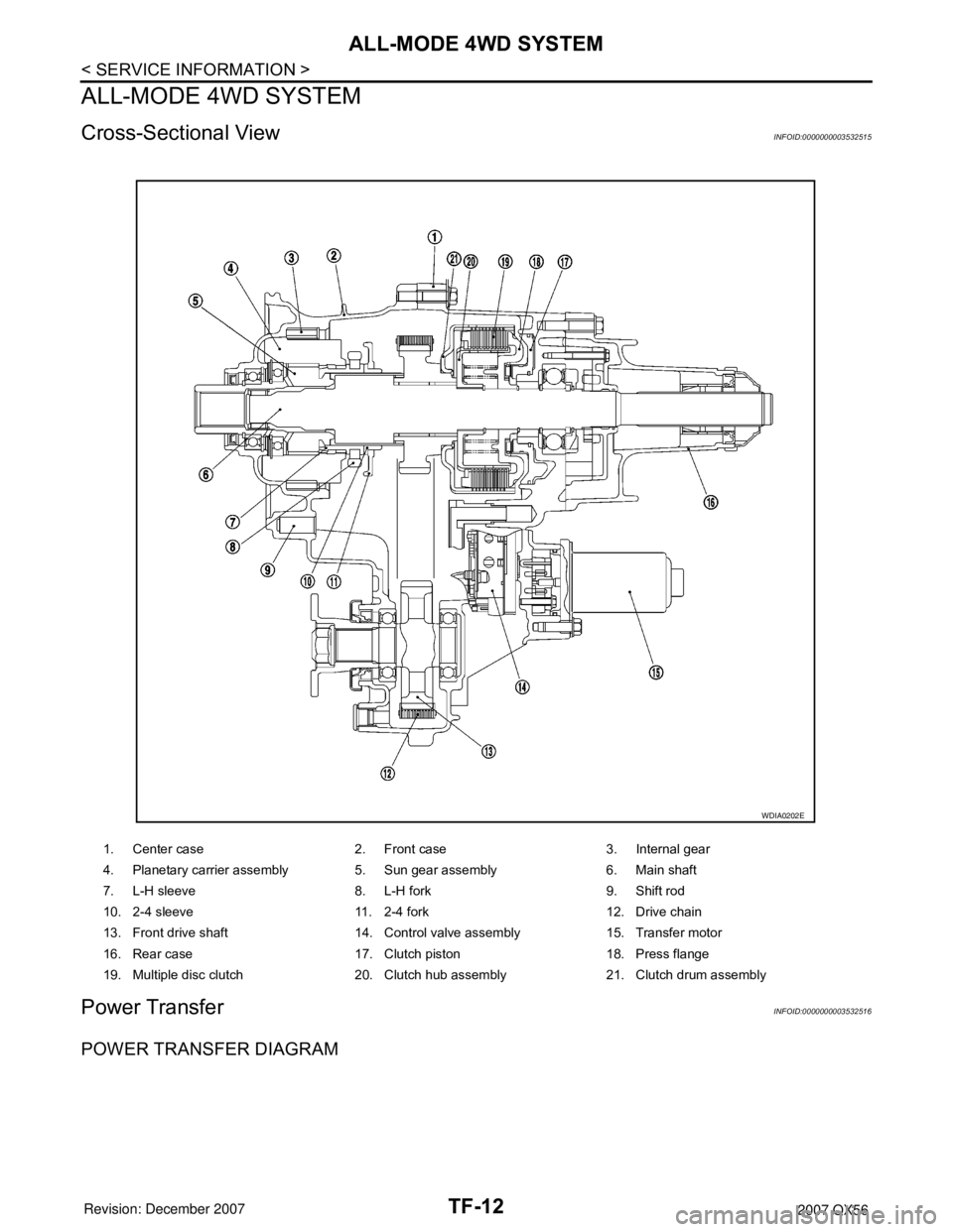
Cross-Sectional ViewINFOID:0000000003532515
Power TransferINFOID:0000000003532516
POWER TRANSFER DIAGRAM
1. Center case 2. Front case 3. Internal gear
4. Planetary carrier assembly 5. Sun gear assembly 6. Main shaft
7. L-H sleeve 8. L-H fork 9. Shift rod
10. 2-4 sleeve 11. 2-4 fork 12. Drive chain
13. Front drive shaft 14. Control valve assembly 15. Transfer motor
16. Rear case 17. Clutch piston 18. Press flange
19. Multiple disc clutch 20. Clutch hub assembly 21. Clutch drum assembly
WDIA0202E
Page 2835 of 3061
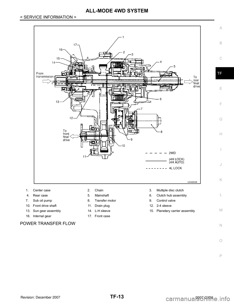
ALL-MODE 4WD SYSTEM
TF-13
< SERVICE INFORMATION >
C
E
F
G
H
I
J
K
L
MA
B
TF
N
O
P
POWER TRANSFER FLOW
1. Center case 2. Chain 3. Multiple disc clutch
4. Rear case 5. Mainshaft 6. Clutch hub assembly
7. Sub oil pump 8. Transfer motor 9. Control valve
10. Front drive shaft 11. Drain plug 12. 2-4 sleeve
13. Sun gear assembly 14. L-H sleeve 15. Planetary carrier assembly
16. Internal gear 17. Front case
LDIA0053E
Page 2839 of 3061

ALL-MODE 4WD SYSTEM
TF-17
< SERVICE INFORMATION >
C
E
F
G
H
I
J
K
L
MA
B
TF
N
O
P
*: After 2.5 seconds have elapsed.
• 4WD shift switch, PNP switch, Neutral-4LO switch, vehicle speed sensor and throttle position sensor are
used in conjunction with the transfer motor.
WAIT DETECTION SWITCH
• The wait detection switch operates when there is “circulating” torque produced in the propeller shaft (L→H)
or when there is a phase difference between 2-4 sleeve and clutch drum (H→L). After the release of the “cir-
culating” torque, the wait detection switch helps provide the 4WD lock gear (clutch drum) shifts. A difference
may occur between the operation of the 4WD shift switch and actual drive mode. At this point, the wait
detection switch senses an actual drive mode.
• The wait detection switch operates as follows.
- 4WD lock gear (clutch drum) locked: ON
- 4WD lock gear (clutch drum) released: OFF
• The wait detection switch senses an actual drive mode and the 4WD shift indicator lamp indicates the vehi-
cle drive mode.
NEUTRAL-4LO SWITCH
The neutral-4LO switch detects that transfer gear is in neutral or 4LO (or shifting from neutral to 4LO) condi-
tion by L-H shift fork position.
AT P S W I T C H
ATP switch detects if transfer gear is in a neutral condition by L-H shift fork position.
NOTE:
Transfer gear may be in a neutral condition in 4H-4LO.
2-4WD SHIFT SOLENOID VALVE
The 2-4WD shift solenoid valve operates to apply oil pressure to the wet-multiplate clutch, depending on the
drive mode. The driving force is transmitted to the front wheels through the clutch so the vehicle is set in the
4WD mode. Setting the vehicle in the 2WD mode requires no pressure buildup. In other words, pressure force
applied to the wet-multiplate clutch becomes zero.
CLUTCH PRESSURE SOLENOID VALVE
The clutch pressure solenoid valve distributes torque (front and rear) in AUTO mode.
4H (LOCK) and 4LO“N” position 0 — ON
“P” position 00 - 0.07/8 OFF*
0.07/8 - 1/8 HOLD
1/8 - MAX ON
Other than “R” position0 < VSS ≤ 50 km/h (31 MPH)
— ON
50 km/h (31 MPH) < VSS < 55
km/h (34 MPH) HOLD
55 km/h (34 MPH) ≤ VSS OFF
“R” position — — ON
“R” position — — ON
AUTO“P” or “N” position00 - 0.07/8 OFF*
0.07/8 - 1/8 HOLD
1/8 - MAX ON
0 < VSS ≤ 50 km/h (31 MPH)
— ON
50 km/h (31 MPH) < VSS < 55
km/h (34 MPH) HOLD
55 km/h (34 MPH) ≤ VSS OFF
Other than “R”, "P" and "N"
position0 < VSS ≤ 50 km/h (31 MPH)
— ON
50 km/h (31 MPH) < VSS < 55
km/h (34 MPH) HOLD
55 km/h (34 MPH) ≤ VSS OFF 4WD shift switch A/T selector lever positionVehicle speed
(VSS)Accelerator pedal positionMotor relay drive
command