Page 1772 of 3061
EM-2
Inspection After Disassembly .................................93SERVICE DATA AND SPECIFICATIONS
(SDS) .............................................................. ..
103
Standard and Limit ............................................... .103
Page 1773 of 3061

PRECAUTIONSEM-3
< SERVICE INFORMATION >
C
DE
F
G H
I
J
K L
M A
EM
NP
O
SERVICE INFORMATION
PRECAUTIONS
Precaution for Supplemental
Restraint System (SRS) "AIR BAG" and "SEAT BELT
PRE-TENSIONER"
INFOID:0000000003531508
The Supplemental Restraint System such as “A IR BAG” and “SEAT BELT PRE-TENSIONER”, used along
with a front seat belt, helps to reduce the risk or severi ty of injury to the driver and front passenger for certain
types of collision. This system includes seat belt switch inputs and dual stage front air bag modules. The SRS
system uses the seat belt switches to determine the front air bag deployment, and may only deploy one front
air bag, depending on the severity of a collision and w hether the front occupants are belted or unbelted.
Information necessary to service the system safely is included in the SRS and SB section of this Service Man-
ual.
WARNING:
• To avoid rendering the SRS inoper ative, which could increase the risk of personal injury or death in
the event of a collision which would result in air bag inflation, all maintenance must be performed by
an authorized NISSAN/INFINITI dealer.
• Improper maintenance, including in correct removal and installation of the SRS, can lead to personal
injury caused by unintentional act ivation of the system. For removal of Spiral Cable and Air Bag
Module, see the SRS section.
• Do not use electrical test equipm ent on any circuit related to the SRS unless instructed to in this
Service Manual. SRS wiring harnesses can be identi fied by yellow and/or orange harnesses or har-
ness connectors.
Precaution for Drain Engine CoolantINFOID:0000000003531509
Drain engine coolant when engine is cooled.
Precaution for Disco nnecting Fuel PipingINFOID:0000000003531510
• Before starting work, make sure no fire or spark producing items are in the work area.
• Release fuel pressure before disconnecting and disassembly.
• After disconnecting pipes, plug openings to stop fuel leakage.
Precaution for Removal and DisassemblyINFOID:0000000003531511
• When instructed to use special service tools, use the spec ified tools. Always be careful to work safely, avoid
forceful or uninstructed operations.
• Exercise maximum care to avoid damage to mating or sliding surfaces.
• Cover openings of engine system with tape or the equiva lent, if necessary, to seal out foreign materials.
• Mark and arrange disassembly parts in an organized way for easy troubleshooting and assembly.
• When loosening nuts and bolts, as a basic rule, start with the one furthest outside, then the one diagonally
opposite, and so on. If the order of loosening is specif ied, do exactly as specified. Power tools may be used
where noted in the step.
Precaution for Inspection, Repair and ReplacementINFOID:0000000003531512
Before repairing or replacing, thoroughly inspect parts. Inspect new replacement parts in the same way, and
replace if necessary.
Precaution for Assembly and InstallationINFOID:0000000003531513
• Use torque wrench to tighten bolts or nuts to specification.
• When tightening nuts and bolts, as a basic rule, equally tighten in several different steps starting with the ones in center, then ones on inside and outside diagonally in this order. If the order of tightening is specified,
do exactly as specified.
• Replace with new gasket, packing, oil seal or O-ring.
• Thoroughly wash, clean, and air-blow each part. Carefully check engine oil or engine coolant passages for any restriction and blockage.
• Avoid damaging sliding or mating surfaces. Completely remove foreign materials such as cloth lint or dust. Before assembly, oil sliding surfaces well.
Page 1774 of 3061

EM-4
< SERVICE INFORMATION >
PRECAUTIONS
• Release air within route when refilling after draining engine coolant.
• Before starting engine, apply fuel pressure to fuel lines with turning ignition switch ON (with engine stopped).
Then make sure that there are no leaks at fuel line connections.
• After repairing, start engine and increase engine s peed to check engine coolant, fuel, oil, and exhaust sys-
tems for leakage.
Parts Requiring Angular TighteningINFOID:0000000003531514
• For final tightening of the following engine parts use Tool:
- Cylinder head bolts
- Main bearing cap bolts
- Connecting rod cap bolts
- Crankshaft pulley bolt (No angle wrench is required as the bolt flange is provided with notches for angle tightening)
• Do not use a torque value for final tightening.
• The torque value for these parts are for a preliminary step.
• Ensure thread and seat surfaces are clean and lightly coated with engine oil.
Precaution for Liquid GasketINFOID:0000000003531515
REMOVAL OF LIQUID GASKET SEALING
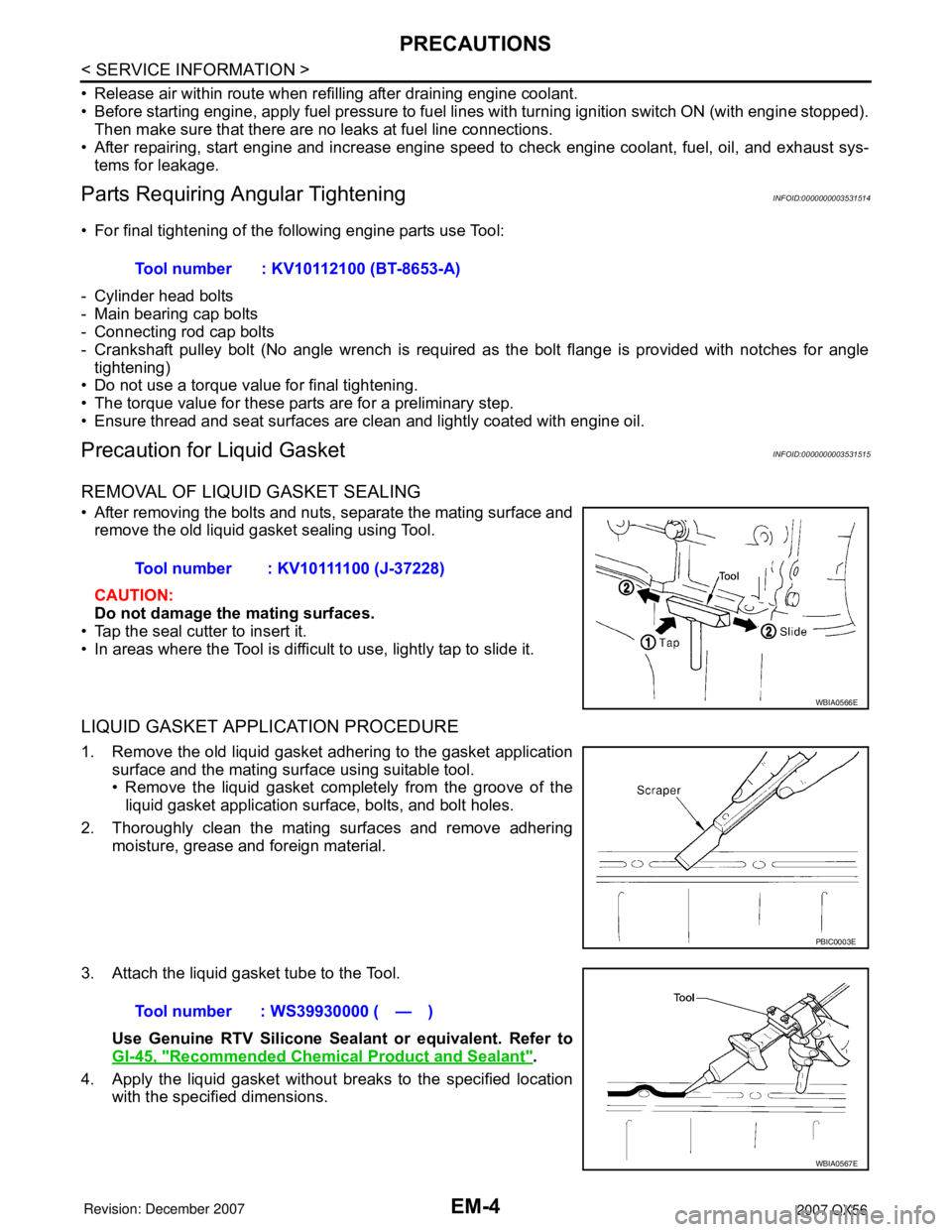
• After removing the bolts and nuts, separate the mating surface and
remove the old liquid gasket sealing using Tool.
CAUTION:
Do not damage the mating surfaces.
• Tap the seal cutter to insert it.
• In areas where the Tool is difficult to use, lightly tap to slide it.
LIQUID GASKET APPLICATION PROCEDURE
1. Remove the old liquid gasket adhering to the gasket application surface and the mating surface using suitable tool.
• Remove the liquid gasket completely from the groove of theliquid gasket application surface, bolts, and bolt holes.
2. Thoroughly clean the mating surfaces and remove adhering moisture, grease and foreign material.
3. Attach the liquid gasket tube to the Tool. Use Genuine RTV Silicone Seal ant or equivalent. Refer to
GI-45, "
Recommended Chemical Product and Sealant".
4. Apply the liquid gasket without breaks to the specified location with the specified dimensions.Tool number : KV10112100 (BT-8653-A)
Tool number : KV10111100 (J-37228)
WBIA0566E
PBIC0003E
Tool number : WS39930000 ( — )
WBIA0567E
Page 1775 of 3061
PRECAUTIONSEM-5
< SERVICE INFORMATION >
C
DE
F
G H
I
J
K L
M A
EM
NP
O
• If there is a groove for the liquid gasket application, apply the
liquid gasket to the groove.
• As for the bolt holes, normally apply the liquid gasket inside
the holes. If specified in t he procedure, it should also be
applied outside the holes.
• Within five minutes of liquid gasket application, install the mat-
ing component.
• If the liquid gasket protrudes, wipe it off immediately.
• Do not retighten after the installation.
• Wait 30 minutes or more after installation before refilling the
engine with engine oil and engine coolant.
CAUTION:
If there are specific instructions in this manual, observe them.
SEM159F
Page 1776 of 3061
EM-6
< SERVICE INFORMATION >
PREPARATION
PREPARATION
Special Service ToolINFOID:0000000003531516
The actual shapes of Kent-Moore tools may differ from those of special service tools illustrated here.
Tool number
(Kent-Moore No.)
Tool name Description
K V 1 0 1111 0 0
(J-37228)
Seal cutter Removing steel oil pan and rear timing chain
case
—
(J-44626)
Air fuel sensor Socket Loosening or tightening air fuel ratio A/F sen-
sor
a: 22 mm (0.87 in)
EG15050500
(J-45402)
Compression gauge adapter Inspecting compression pressure
KV10116200
(J-26336-A)
Valve spring compressor
1. KV10115900
(J-26336-20)
Attachment
2. KV10109220
(—)
Adapter Disassembling valve mechanism
Part (1) is a component of KV10116200 (J-
26336-A), but part (2) is not.
KV10112100
(BT-8653-A)
Angle wrench Tightening bolts for cylinder head, main bear-
ing cap and connecting rod cap
KV10107902
(J-38959)
Valve oil seal puller Removing valve oil seal
S-NT046
LBIA0444E
ZZA1225D
PBIC1650E
S-NT014
S-NT011
Page 1777 of 3061
PREPARATIONEM-7
< SERVICE INFORMATION >
C
DE
F
G H
I
J
K L
M A
EM
NP
O
KV10115600
(J-38958)
Valve oil seal drift
Installing valve oil seal
Use side A.
a: 20 (0.79) dia. d: 8 (0.31) dia.
b: 13 (0.51) dia. e: 10.7 (0.421) dia.
c: 10.3 (0.406) dia. f: 5 (0.20) dia.
Unit: mm (in)
EM03470000
(J-8037)
Piston ring compressor Installing piston assembly into cylinder bore
ST16610001
(J-23907)
Pilot bushing puller Removing crankshaft pilot bushing
WS39930000
(—)
Tube presser Pressing the tube of liquid gasket
—
(J-47245)
Ring gear stopper Removing and installing crankshaft pulley
16441 6N210
(J-45488)
Quick connector release Removing fuel tube quick connectors in en-
gine room
(Available in SEC. 164 of PARTS CATALOG:
Part No. 16441 6N210)
—
(J-46535)
Drive belt tension releaser Releasing drive belt tension
Tool number
(Kent-Moore No.)
Tool name
Description
S-NT603
S-NT044
S-NT045
S-NT052
LBIA0451E
PBIC0198E
WBIA0536E
Page 1778 of 3061
EM-8
< SERVICE INFORMATION >
PREPARATION
Commercial Service Tool
INFOID:0000000003531517
(Kent-Moore No.)
Tool name Description
Power tool Loosening bolts and nuts
Spark plug wrench Removing and installing spark plug
(J-24239-01)
Cylinder head bolt wrench Loosening and tightening cylinder head bolt,
and use with angle wrench [SST: KV10112100
(BT-8653-A)]
a: 13 (0.51) dia.
b: 12 (0.47)
c: 10 (0.39)
Unit: mm (in)
Valve seat cutter set Finishing valve seat dimensions
Pulley puller Removing crankshaft pulley
Piston ring expander Removing and installing piston ring
PBIC0190E
S-NT047
NT583
S-NT048
ZZA0010D
S-NT030
Page 1779 of 3061

PREPARATIONEM-9
< SERVICE INFORMATION >
C
DE
F
G H
I
J
K L
M A
EM
NP
O
Valve guide drift Removing and installing valve guide
Intake & Exhaust:
a: 9.5 mm (0.374 in) dia.
b: 5.5 mm (0.217 in) dia.
Valve guide reamer 1: Reaming valve guide hole 2: Reaming hole for oversize valve guide
Intake & Exhaust:
d
1: 6.0 mm (0.236 in) dia.
d
2: 10.175 - 10.196 mm (0.4006 - 0.4014 in)
dia.
Front oil seal drift Installing front oil seal
Rear oil seal drift Installing rear oil seal
(J-43897-18)
(J-43897-12)
Oxygen sensor thread cleaner Reconditioning the exhaust system threads
before installing a new A/F sensor and heated
oxygen sensor (Use with anti-seize lubricant
shown below.)
a: J-43897-18 (18 mm dia.) (0.71 in) for zir-
conia heated oxygen sensor
b: J-43897-12 (12 mm dia.) (0.55 in) for tita-
nia heated oxygen sensor
Anti-seize lubricant (Permatex 133AR
or equivalent meeting MIL specifica-
tion MIL-A-907) Lubricating A/F sensors and heated oxygen
sensor thread cleaning tool when recondition-
ing exhaust system threads
(Kent-Moore No.)
Tool name
Description
S-NT015
S-NT016
ZZA0012D
ZZA0025D
AEM488
AEM489