Page 833 of 3061
![INFINITI QX56 2007 Factory Service Manual BL-122
< SERVICE INFORMATION >
IVIS (INFINITI VEHICLE IMMOBILIZER SYSTEM-NATS)
Detected items
[IVIS (NATS) program card screen
terms]P No. Code
(Self-diagnostic
result of “EN-
GINE”)Malfunction INFINITI QX56 2007 Factory Service Manual BL-122
< SERVICE INFORMATION >
IVIS (INFINITI VEHICLE IMMOBILIZER SYSTEM-NATS)
Detected items
[IVIS (NATS) program card screen
terms]P No. Code
(Self-diagnostic
result of “EN-
GINE”)Malfunction](/manual-img/42/57029/w960_57029-832.png)
BL-122
< SERVICE INFORMATION >
IVIS (INFINITI VEHICLE IMMOBILIZER SYSTEM-NATS)
Detected items
[IVIS (NATS) program card screen
terms]P No. Code
(Self-diagnostic
result of “EN-
GINE”)Malfunction is detected when.....Reference
page
CHAIN OF ECM-IMMU
[P1612]NATS MAL-
FUNCTION
P1612Communication impossible between ECM and BCM
In rare case, “CHAIN OF ECM-IMMU” might be stored
during key registration procedure, even if the system is not
malfunctioning.Refer to
BL-125
.
DIFFERENCE OF KEY
[P1615]NATS MAL-
FUNCTION
P1615BCM can receive the key ID signal but the result of ID ver-
ification between key ID and BCM is NG.Refer to
BL-126
.
CHAIN OF IMMU-KEY
[P1614]NATS MAL-
FUNCTION
P1614BCM cannot receive the key ID signal.Refer to
BL-129
.
ID DISCORD, IMM-ECM
[P1611]NATS MAL-
FUNCTION
P1611The result of ID verification between BCM and ECM is NG.
System initialization is required.Refer to
BL-127
.
LOCK MODE
[P1610]NATS MAL-
FUNCTION
P1610When the starting operation is carried out five or more
times consecutively under the following conditions, IVIS
(NATS) will shift the mode to one which prevents the en-
gine from being started.
• Unregistered ignition key is used.
• BCM or ECM malfunctioning.Refer to
BL-128
.
DON'T ERASE BEFORE CHECK-
ING ENG DIAG—All engine trouble codes except IVIS (NATS) trouble code
has been detected in ECM.Refer to
BL-123
.
Page 835 of 3061

BL-124
< SERVICE INFORMATION >
IVIS (INFINITI VEHICLE IMMOBILIZER SYSTEM-NATS)
Self-diagnosis related item
*: When IVIS (NATS) detects a malfunction, the security indicator lights up while ignition key is in the “ON” position.
SYMPTOM MATRIX CHART 2
SymptomDisplayed “SELF-DIAG
RESULTS” on CON-
SULT-II screen.Diagnostic Procedure
(Reference page)System
(Malfunctioning part or
mode)Reference Part No. Of Il-
lustration On System Di-
agram
• Security indicator light-
ing up*
• Engine cannot be
startedCHAIN OF ECM-IMMU
[P1612]PROCEDURE 1
(BL-125
)In rare case, “CHAIN OF
ECM-IMMU” might be
stored during key regis-
tration procedure, even if
the system is not mal-
functioning.—
Open circuit in battery
voltage line of BCM cir-
cuitC1
Open circuit in ignition
line of BCM circuitC2
Open circuit in ground
line of BCM circuitC3
Open or short circuit be-
tween BCM and ECM
communication lineC4
ECM B
BCM A
DIFFERENCE OF KEY
[P1615]PROCEDURE 2
(BL-126
)Unregistered key D
BCM A
CHAIN OF IMMU-KEY
[P1614]PROCEDURE 5
(BL-129
)Malfunction of key ID
chipE5
Communication line be-
tween ANT/ AMP and
BCM:
Open circuit or short cir-
cuit of battery voltage
line or ground lineE1
E2
Open circuit in power
source line of ANT/ AMP
circuitE3
Open circuit in ground
line of ANT/ AMP circuitE4
NATS antenna amp. E6
BCM A
ID DISCORD, IMM-ECM
[P1611]PROCEDURE 3
(BL-127
)System initialization has
not yet been completed.F
ECM B
LOCK MODE
[P1610]PROCEDURE 4
(BL-128
)LOCK MODE D
Security indicator lighting
up*DON'T ERASE BEFORE
CHECKING ENG DIAGWORK FLOW
(BL-123
)Engine trouble data and
IVIS (NATS) trouble data
have been detected in
ECM—
Page 837 of 3061

BL-126
< SERVICE INFORMATION >
IVIS (INFINITI VEHICLE IMMOBILIZER SYSTEM-NATS)
OK or NG
OK >> GO TO 3.
NG >> Check the following:
• 50A fusible link (letter f , located in fuse and fusible
link box)
• Harness for open or short between fuse and BCM
connector. Ref. Part No. C1
3.CHECK IGN SW. ON SIGNAL
1. Turn ignition switch ON.
2. Check voltage between BCM connector M18 terminal 38 and ground.
OK or NG
OK >> GO TO 4.
NG >> Check the following:
• 10A fuse [No. 59, located in the fuse and relay box]
• Harness for open or short between fuse and BCM
connector. Ref. part No. C2
4.CHECK GROUND CIRCUIT FOR BCM
1. Turn ignition switch OFF.
2. Check continuity between BCM connector M18 terminal 67 and ground.
OK or NG
OK >> GO TO 5.
NG >> Repair or replace harness. Ref. part No. C3
5.REPLACE BCM
1. Replace BCM. Ref. part No. A
2. Perform initialization with CONSULT-II.
For initialization, refer to “CONSULT-II Operation Manual NATS-IVIS/NVIS”.
Does the engine start?
YES >> BCM is malfunctioning.
NO >> ECM is malfunctioning.
• Replace ECM. Ref. part No. B
• Perform initialization or re-communicating function.
• For initialization, refer to “CONSULT-II Operation Manual NATS-IVIS/NVIS”.
• For re-communicating function, refer to BL-117, "
ECM Re-communicating Function".
Diagnosis Procedure 2INFOID:0000000003532996
Self-diagnostic results:
“DIFFERENCE OF KEY” displayed on CONSULT-II screen
1.CONFIRM SELF-DIAGNOSTIC RESULTS70 - Ground :Battery voltage
LIIA1279E
38 - Ground :Battery voltage
LIIA0527E
67 - Ground :Continuity should exist.
LIIA1040E
Page 840 of 3061

IVIS (INFINITI VEHICLE IMMOBILIZER SYSTEM-NATS)
BL-129
< SERVICE INFORMATION >
C
D
E
F
G
H
J
K
L
MA
B
BL
N
O
P
For initialization, refer to “CONSULT-II Operation Manual NATS-
IVIS/NVIS”.
NOTE:
If the initialization is not completed or malfunctions, CONSULT-II
shows the message on the screen.
Can the system be initialized?
YES >> System is OK. BCM is malfunctioning. Ref. part No. A
NO >> ECM is malfunctioning.
• Replace ECM. Ref. part No. B
• Perform initialization with CONSULT-II.
For initialization, refer to “CONSULT-II Operation Man-
ual NATS-IVIS/NVIS”.
Diagnosis Procedure 5INFOID:0000000003532999
Self-diagnostic results:
“CHAIN OF IMMU-KEY” displayed on CONSULT-II screen
1.CONFIRM SELF-DIAGNOSTIC RESULTS
Confirm SELF-DIAGNOSTIC RESULTS “CHAIN OF IMMU-KEY”
displayed on CONSULT-II screen.
Is CONSULT-II screen displayed as above?
YES >> GO TO 2.
NO >> GO TO BL-123, "
Trouble Diagnosis".
2.CHECK NATS ANTENNA AMP. INSTALLATION
Check NATS antenna amp. installation. Refer to BL-132, "
How to Replace NATS Antenna Amp".
OK or NG
OK >> GO TO 3.
NG >> Reinstall NATS antenna amp. correctly.
3.CHECK IVIS (NATS) IGNITION KEY ID CHIP
Start engine with another registered NATS ignition key.
Does the engine start?
YES >> Ignition key ID chip is malfunctioning.
• Replace the ignition key. Ref. part No. E5
• Perform initialization with CONSULT-II.
For initialization, refer to “CONSULT-II Operation Manual NATS-IVIS/NVIS”.
NO >> GO TO 4.
4.CHECK POWER SUPPLY FOR NATS ANTENNA AMP.
1. Turn ignition switch ON.
2. Check voltage between NATS antenna amp. connector M21 terminal 1 and ground.
SEL297W
PIIA1263E
Page 842 of 3061

IVIS (INFINITI VEHICLE IMMOBILIZER SYSTEM-NATS)
BL-131
< SERVICE INFORMATION >
C
D
E
F
G
H
J
K
L
MA
B
BL
N
O
P
OK or NG
OK >> GO TO 7.
NG >> • Repair or replace harness.
NOTE:
If harness is OK, replace BCM, perform initialization with CONSULT-II. For initialization, refer to
“CONSULT-II Operation Manual NATS-IVIS/NVIS”.
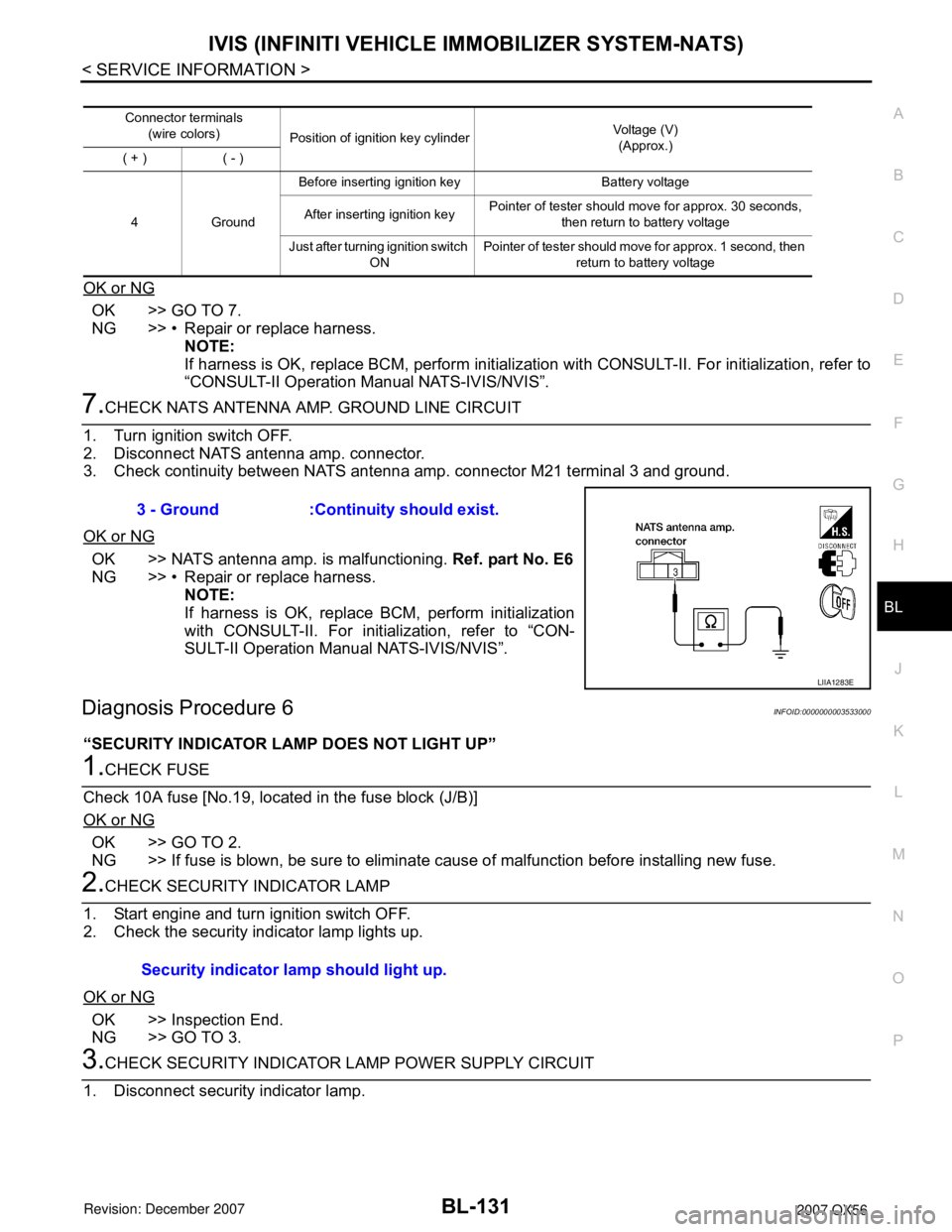
7.CHECK NATS ANTENNA AMP. GROUND LINE CIRCUIT
1. Turn ignition switch OFF.
2. Disconnect NATS antenna amp. connector.
3. Check continuity between NATS antenna amp. connector M21 terminal 3 and ground.
OK or NG
OK >> NATS antenna amp. is malfunctioning. Ref. part No. E6
NG >> • Repair or replace harness.
NOTE:
If harness is OK, replace BCM, perform initialization
with CONSULT-II. For initialization, refer to “CON-
SULT-II Operation Manual NATS-IVIS/NVIS”.
Diagnosis Procedure 6INFOID:0000000003533000
“SECURITY INDICATOR LAMP DOES NOT LIGHT UP”
1.CHECK FUSE
Check 10A fuse [No.19, located in the fuse block (J/B)]
OK or NG
OK >> GO TO 2.
NG >> If fuse is blown, be sure to eliminate cause of malfunction before installing new fuse.
2.CHECK SECURITY INDICATOR LAMP
1. Start engine and turn ignition switch OFF.
2. Check the security indicator lamp lights up.
OK or NG
OK >> Inspection End.
NG >> GO TO 3.
3.CHECK SECURITY INDICATOR LAMP POWER SUPPLY CIRCUIT
1. Disconnect security indicator lamp.
Connector terminals
(wire colors)
Position of ignition key cylinderVoltage (V)
(Approx.)
( + ) ( - )
4GroundBefore inserting ignition key Battery voltage
After inserting ignition keyPointer of tester should move for approx. 30 seconds,
then return to battery voltage
Just after turning ignition switch
ONPointer of tester should move for approx. 1 second, then
return to battery voltage
3 - Ground :Continuity should exist.
LIIA1283E
Security indicator lamp should light up.
Page 904 of 3061

BR-6
< SERVICE INFORMATION >
BRAKE PEDAL
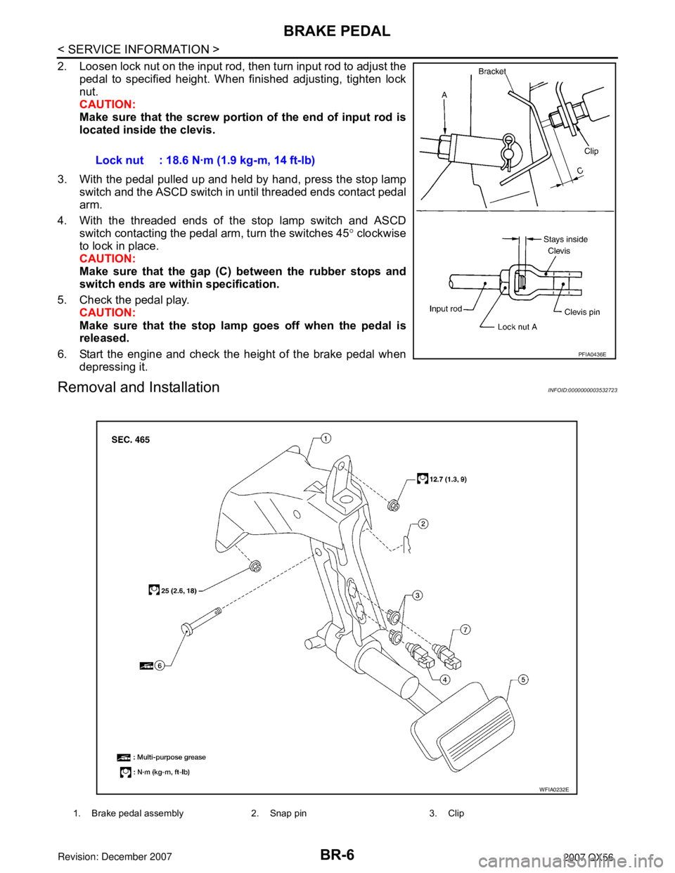
2. Loosen lock nut on the input rod, then turn input rod to adjust the
pedal to specified height. When finished adjusting, tighten lock
nut.
CAUTION:
Make sure that the screw portion of the end of input rod is
located inside the clevis.
3. With the pedal pulled up and held by hand, press the stop lamp
switch and the ASCD switch in until threaded ends contact pedal
arm.
4. With the threaded ends of the stop lamp switch and ASCD
switch contacting the pedal arm, turn the switches 45° clockwise
to lock in place.
CAUTION:
Make sure that the gap (C) between the rubber stops and
switch ends are within specification.
5. Check the pedal play.
CAUTION:
Make sure that the stop lamp goes off when the pedal is
released.
6. Start the engine and check the height of the brake pedal when
depressing it.
Removal and InstallationINFOID:0000000003532723
Lock nut : 18.6 N·m (1.9 kg-m, 14 ft-lb)
PFIA0436E
1. Brake pedal assembly 2. Snap pin 3. Clip
WFIA0232E
Page 910 of 3061
BR-12
< SERVICE INFORMATION >
BRAKE PIPING AND HOSE
Inspection After Installation
INFOID:0000000003532730
CAUTION:
If a leak is detected at the connections, retighten it or, if necessary, replace the damaged part.
1. Check brake tubes and hose connections for fluid leaks, damage, twist, deformation, contact with other
parts, and loose connections. Replace any damage parts.
2. While depressing brake pedal under a force of 785 N (80 kg-f, 177 lb-f) with engine running for approxi-
mately 5 seconds, check for fluid leakage from each part.
Page 913 of 3061

BRAKE BOOSTER
BR-15
< SERVICE INFORMATION >
C
D
E
G
H
I
J
K
L
MA
B
BR
N
O
P
BRAKE BOOSTER
On-Vehicle ServiceINFOID:0000000003532734
OPERATING CHECK
With engine stopped, change the vacuum to the atmospheric pres-
sure by depressing brake pedal several times. Then with brake
pedal fully depressed, start engine and when the vacuum pressure
reaches the standard, make sure the clearance between brake pedal
and floor panel decreases.
CAUTION:
Depressing pedal interval is approximately 5 seconds.
AIRTIGHT CHECK
• Run engine at idle for approximately 1 minute, and stop it after
applying vacuum to booster. Depress brake pedal normally to
change the vacuum to the atmospheric pressure. Make sure dis-
tance between brake pedal and floor panel gradually increases.
• Depress brake pedal while engine is running and stop engine with
pedal depressed. The pedal stroke should not change after holding
pedal down for 30 seconds.
CAUTION:
Depressing pedal interval is approximately 5 seconds.
Removal and InstallationINFOID:0000000003532735
REMOVAL
CAUTION:
• Be careful not to deform or bend brake piping while removing and installing brake booster.
• Replace clevis pin if it is damaged.
BRA0037D
SBR365AA
1. Reservoir tank 2. Brake master cylinder 3. Gasket
4. Brake pedal 5. Lock nut 6. Spacer block
7. Brake booster 8. Active booster 9. Delta stroke sensor
WFIA0381E