2007 INFINITI QX56 ECO mode
[x] Cancel search: ECO modePage 1168 of 3061
TROUBLE DIAGNOSIS
EC-85
< SERVICE INFORMATION >
C
D
E
F
G
H
I
J
K
L
MA
EC
N
P O
7.PERFORM DATA MONITOR (SPEC) MODE
With CONSULT-II
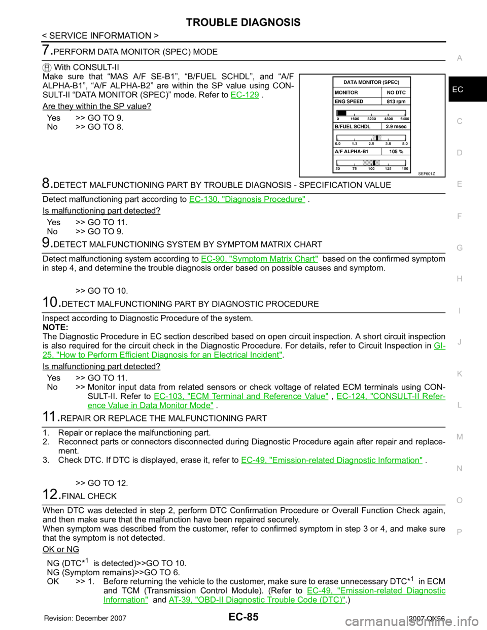
Make sure that “MAS A/F SE-B1”, “B/FUEL SCHDL”, and “A/F
ALPHA-B1”, “A/F ALPHA-B2” are within the SP value using CON-
SULT-II “DATA MONITOR (SPEC)” mode. Refer to EC-129
.
Are they within the SP value?
Yes >> GO TO 9.
No >> GO TO 8.
8.DETECT MALFUNCTIONING PART BY TROUBLE DIAGNOSIS - SPECIFICATION VALUE
Detect malfunctioning part according to EC-130, "
Diagnosis Procedure" .
Is malfunctioning part detected?
Yes >> GO TO 11.
No >> GO TO 9.
9.DETECT MALFUNCTIONING SYSTEM BY SYMPTOM MATRIX CHART
Detect malfunctioning system according to EC-90, "
Symptom Matrix Chart" based on the confirmed symptom
in step 4, and determine the trouble diagnosis order based on possible causes and symptom.
>> GO TO 10.
10.DETECT MALFUNCTIONING PART BY DIAGNOSTIC PROCEDURE
Inspect according to Diagnostic Procedure of the system.
NOTE:
The Diagnostic Procedure in EC section described based on open circuit inspection. A short circuit inspection
is also required for the circuit check in the Diagnostic Procedure. For details, refer to Circuit Inspection in GI-
25, "How to Perform Efficient Diagnosis for an Electrical Incident".
Is malfunctioning part detected?
Yes >> GO TO 11.
No >> Monitor input data from related sensors or check voltage of related ECM terminals using CON-
SULT-II. Refer to EC-103, "
ECM Terminal and Reference Value" , EC-124, "CONSULT-II Refer-
ence Value in Data Monitor Mode" .
11 .REPAIR OR REPLACE THE MALFUNCTIONING PART
1. Repair or replace the malfunctioning part.
2. Reconnect parts or connectors disconnected during Diagnostic Procedure again after repair and replace-
ment.
3. Check DTC. If DTC is displayed, erase it, refer to EC-49, "
Emission-related Diagnostic Information" .
>> GO TO 12.
12.FINAL CHECK
When DTC was detected in step 2, perform DTC Confirmation Procedure or Overall Function Check again,
and then make sure that the malfunction have been repaired securely.
When symptom was described from the customer, refer to confirmed symptom in step 3 or 4, and make sure
that the symptom is not detected.
OK or NG
NG (DTC*1 is detected)>>GO TO 10.
NG (Symptom remains)>>GO TO 6.
OK >> 1. Before returning the vehicle to the customer, make sure to erase unnecessary DTC*
1 in ECM
and TCM (Transmission Control Module). (Refer to EC-49, "
Emission-related Diagnostic
Information" and AT-39, "OBD-II Diagnostic Trouble Code (DTC)".)
SEF601Z
Page 1194 of 3061
TROUBLE DIAGNOSIS
EC-111
< SERVICE INFORMATION >
C
D
E
F
G
H
I
J
K
L
MA
EC
N
P O
: Average voltage for pulse signal (Actual pulse signal can be confirmed by oscilloscope.)
*:Before measuring the terminal voltage, confirm that the battery is fully charged. Refer to SC-4
.
CONSULT-II Function (ENGINE)INFOID:0000000003531626
FUNCTION
108 BR/WICC brake switch
(Models with ICC system)
ASCD brake switch
(Models with ASCD system)[Ignition switch: ON]
• Brake pedal: Slightly depressedApproximately 0V
[Ignition switch: ON]
• Brake pedal: Fully releasedBATTERY VOLTAGE
(11 - 14V)
109 L/W Ignition switch[Ignition switch: OFF]0V
[Ignition switch: ON]BATTERY VOLTAGE
(11 - 14V)
111 W / BECM relay
(Self shut-off)[Engine is running]
[Ignition switch: OFF]
• For a few seconds after turning ignition
switch OFF0 - 1.5V
[Ignition switch: OFF]
• More than a few seconds after turning igni-
tion switch OFFBATTERY VOLTAGE
(11 - 14V)
11 3 G R F u e l p u m p r e l a y[Ignition switch: ON]
• For 1 second after turning ignition switch
ON
[Engine is running]0 - 1.5V
[Ignition switch: ON]
• More than 1 second after turning ignition
switch ONBATTERY VOLTAGE
(11 - 14V)
11 5
11 6B
B/WECM ground[Engine is running]
• Idle speedBody ground
11 7 L / YEVAP canister vent control
valve[Ignition switch: ON]BATTERY VOLTAGE
(11 - 14V)
11 9
120BR
BRPower supply for ECM[Ignition switch: ON]BATTERY VOLTAGE
(11 - 14V)
121 WPower supply for ECM
(Back-up)[Ignition switch: OFF]BATTERY VOLTAGE
(11 - 14V) TER-
MI-
NAL
NO.WIRE
COLORITEM CONDITION DATA (DC Voltage)
Diagnostic test mode Function
Work supportThis mode enables a technician to adjust some devices faster and more accurately by following the in-
dications on the CONSULT-II unit.
Self-diagnostic resultsSelf-diagnostic results such as 1st trip DTC, DTCs and 1st trip freeze frame data or freeze frame data
can be read and erased quickly.*
Data monitor Input/Output data in the ECM can be read.
Data monitor (SPEC)Input/Output of the specification for Basic fuel schedule, AFM, A/F feedback control value and the other
data monitor items can be read.
CAN diagnostic support mon-
itorThe results of transmit/receive diagnosis of CAN communication can be read.
Active testDiagnostic Test Mode in which CONSULT-II drives some actuators apart from the ECMs and also shifts
some parameters in a specified range.
DTC & SRT confirmation The status of system monitoring tests and the self-diagnosis status/result can be confirmed.
Function test This mode is used to inform customers when their vehicle condition requires periodic maintenance.
ECM part number ECM part number can be read.
Page 1198 of 3061

TROUBLE DIAGNOSIS
EC-115
< SERVICE INFORMATION >
C
D
E
F
G
H
I
J
K
L
MA
EC
N
P O
*: The item is the same as that of 1st trip freeze frame data.
DATA MONITOR MODE
Monitored Item
×: Applicable
B/FUEL SCHDL
[msec]• The base fuel schedule at the moment a malfunction is detected is displayed.
INT/A TEMP SE
[°C] or [°F]• The intake air temperature at the moment a malfunction is detected is displayed. Freeze frame data
item*Description
Monitored item
[Unit]ECM IN-
PUT SIG-
NALSMAIN
SIGNALSDescription Remarks
ENG SPEED [rpm]×ו Indicates the engine speed computed
from the signal of the crankshaft position
sensor (POS) and camshaft position
sensor (PHASE).• Accuracy becomes poor if engine
speed drops below the idle rpm.
• If the signal is interrupted while the en-
gine is running, an abnormal value may
be indicated.
MAS A/F SE-B1 [V]×ו The signal voltage of the mass air flow
sensor is displayed.• When the engine is stopped, a certain
value is indicated.
B/FUEL SCHDL
[msec]ו Base fuel schedule indicates the fuel in-
jection pulse width programmed into
ECM, prior to any learned on board cor-
rection.
A/F ALPHA-B1 [%]×
• The mean value of the air-fuel ratio feed-
back correction factor per cycle is indi-
cated.• When the engine is stopped, a certain
value is indicated.
• This data also includes the data for the
air-fuel ratio learning control. A/F ALPHA-B2 [%]×
COOLAN TEMP/S
[°C] or [°F]×ו The engine coolant temperature (deter-
mined by the signal voltage of the engine
coolant temperature sensor) is dis-
played.• When the engine coolant temperature
sensor is open or short-circuited, ECM
enters fail-safe mode. The engine cool-
ant temperature determined by the
ECM is displayed.
A/F SEN1 (B1) [V]××
• The A/F signal computed from the input
signal of the A/F sensor 1 is displayed.
A/F SEN1 (B2) [V]×
HO2S2 (B1) [V]×
• The signal voltage of the heated oxygen
sensor 2 is displayed.
HO2S2 (B2) [V]×
HO2S2 MNTR (B1)
[RICH/LEAN]ו Display of heated oxygen sensor 2 sig-
nal:
RICH: means the amount of oxygen after
three way catalyst is relatively small.
LEAN: means the amount of oxygen af-
ter three way catalyst is relatively large.• When the engine is stopped, a certain
value is indicated.
HO2S2 MNTR (B2)
[RICH/LEAN]×
VHCL SPEED SE
[km/h] or [mph]×ו The vehicle speed computed from the
vehicle speed signal sent from combina-
tion meter is displayed.
BATTERY VOLT [V]×ו The power supply voltage of ECM is dis-
played.
ACCEL SEN 1 [V]××
• The accelerator pedal position sensor
signal voltage is displayed.• ACCEL SEN 2 signal is converted by
ECM internally. Thus, it differs from
ECM terminal voltage signal. ACCEL SEN 2 [V]×
THRTL SEN 1 [V]××
• The throttle position sensor signal volt-
age is displayed.• THRTL SEN 2 signal is converted by
ECM internally. Thus, it differs from
ECM terminal voltage signal. THRTL SEN 2 [V]×
Page 1204 of 3061
TROUBLE DIAGNOSIS
EC-121
< SERVICE INFORMATION >
C
D
E
F
G
H
I
J
K
L
MA
EC
N
P O
*: DTC P1442 and P1456 does not apply to JA60 models but appears in DTC Work Support Mode screens.
REAL TIME DIAGNOSIS IN DATA MONITOR MODE (RECORDING VEHICLE DATA)
Description
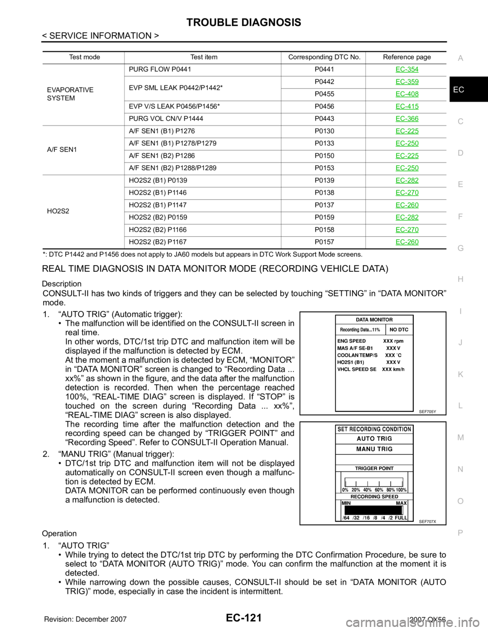
CONSULT-II has two kinds of triggers and they can be selected by touching “SETTING” in “DATA MONITOR”
mode.
1. “AUTO TRIG” (Automatic trigger):
• The malfunction will be identified on the CONSULT-II screen in
real time.
In other words, DTC/1st trip DTC and malfunction item will be
displayed if the malfunction is detected by ECM.
At the moment a malfunction is detected by ECM, “MONITOR”
in “DATA MONITOR” screen is changed to “Recording Data ...
xx%” as shown in the figure, and the data after the malfunction
detection is recorded. Then when the percentage reached
100%, “REAL-TIME DIAG” screen is displayed. If “STOP” is
touched on the screen during “Recording Data ... xx%”,
“REAL-TIME DIAG” screen is also displayed.
The recording time after the malfunction detection and the
recording speed can be changed by “TRIGGER POINT” and
“Recording Speed”. Refer to CONSULT-II Operation Manual.
2. “MANU TRIG” (Manual trigger):
• DTC/1st trip DTC and malfunction item will not be displayed
automatically on CONSULT-II screen even though a malfunc-
tion is detected by ECM.
DATA MONITOR can be performed continuously even though
a malfunction is detected.
Operation
1. “AUTO TRIG”
• While trying to detect the DTC/1st trip DTC by performing the DTC Confirmation Procedure, be sure to
select to “DATA MONITOR (AUTO TRIG)” mode. You can confirm the malfunction at the moment it is
detected.
• While narrowing down the possible causes, CONSULT-II should be set in “DATA MONITOR (AUTO
TRIG)” mode, especially in case the incident is intermittent.
Test mode Test item Corresponding DTC No. Reference page
EVAPORATIVE
SYSTEMPURG FLOW P0441 P0441EC-354
EVP SML LEAK P0442/P1442*P0442EC-359P0455EC-408
EVP V/S LEAK P0456/P1456* P0456EC-415
PURG VOL CN/V P1444 P0443EC-366
A/F SEN1A/F SEN1 (B1) P1276 P0130EC-225A/F SEN1 (B1) P1278/P1279 P0133EC-250
A/F SEN1 (B2) P1286 P0150EC-225
A/F SEN1 (B2) P1288/P1289 P0153EC-250
HO2S2HO2S2 (B1) P0139 P0139EC-282
HO2S2 (B1) P1146 P0138EC-270
HO2S2 (B1) P1147 P0137EC-260
HO2S2 (B2) P0159 P0159EC-282
HO2S2 (B2) P1166 P0158EC-270
HO2S2 (B2) P1167 P0157EC-260
SEF705Y
SEF707X
Page 1217 of 3061
EC-134
< SERVICE INFORMATION >
TROUBLE DIAGNOSIS - SPECIFICATION VALUE
12.CHECK A/F SENSOR 1 FUNCTION
Perform all DTC Confirmation Procedure related with A/F sensor 1.
• For DTC P0130, P0150, refer to EC-225, "
DTC Confirmation Procedure" .
• For DTC P0131, P0151, refer to EC-234, "
DTC Confirmation Procedure" .
• For DTC P0132, P0132, refer to EC-242, "
DTC Confirmation Procedure" .
• For DTC P0133, P0153, refer to EC-250, "
DTC Confirmation Procedure" .
• For DTC P2A00, P2A03, refer to EC-588, "
DTC Confirmation Procedure" .
OK or NG
OK >> GO TO 15.
NG >> GO TO 13.
13.CHECK A/F SENSOR 1 CIRCUIT
Perform Diagnostic Procedure according to corresponding DTC.
>> GO TO 14.
14.CHECK “A/F ALPHA-B1”, “A/F ALPHA-B2”
1. Start engine.
2. Select “A/F ALPHA-B1”, “A/F ALPHA-B2” in “DATA MONITOR (SPEC)” mode, and make sure that the
each indication is within the SP value.
OK or NG
OK >>INSPECTION END
NG >> GO TO 15.
15.DISCONNECT AND RECONNECT ECM HARNESS CONNECTOR
1. Stop the engine.
2. Disconnect ECM harness connector. Check pin terminal and connector for damage, and then reconnect it.
>> GO TO 16.
16.CHECK “A/F ALPHA-B1”, “A/F ALPHA-B2”
1. Start engine.
2. Select “A/F ALPHA-B1”, “A/F ALPHA-B2” in “DATA MONITOR (SPEC)” mode, and make sure that the
each indication is within the SP value.
OK or NG
OK >>INSPECTION END
NG >> Detect malfunctioning part according to EC-90, "
Symptom Matrix Chart" .
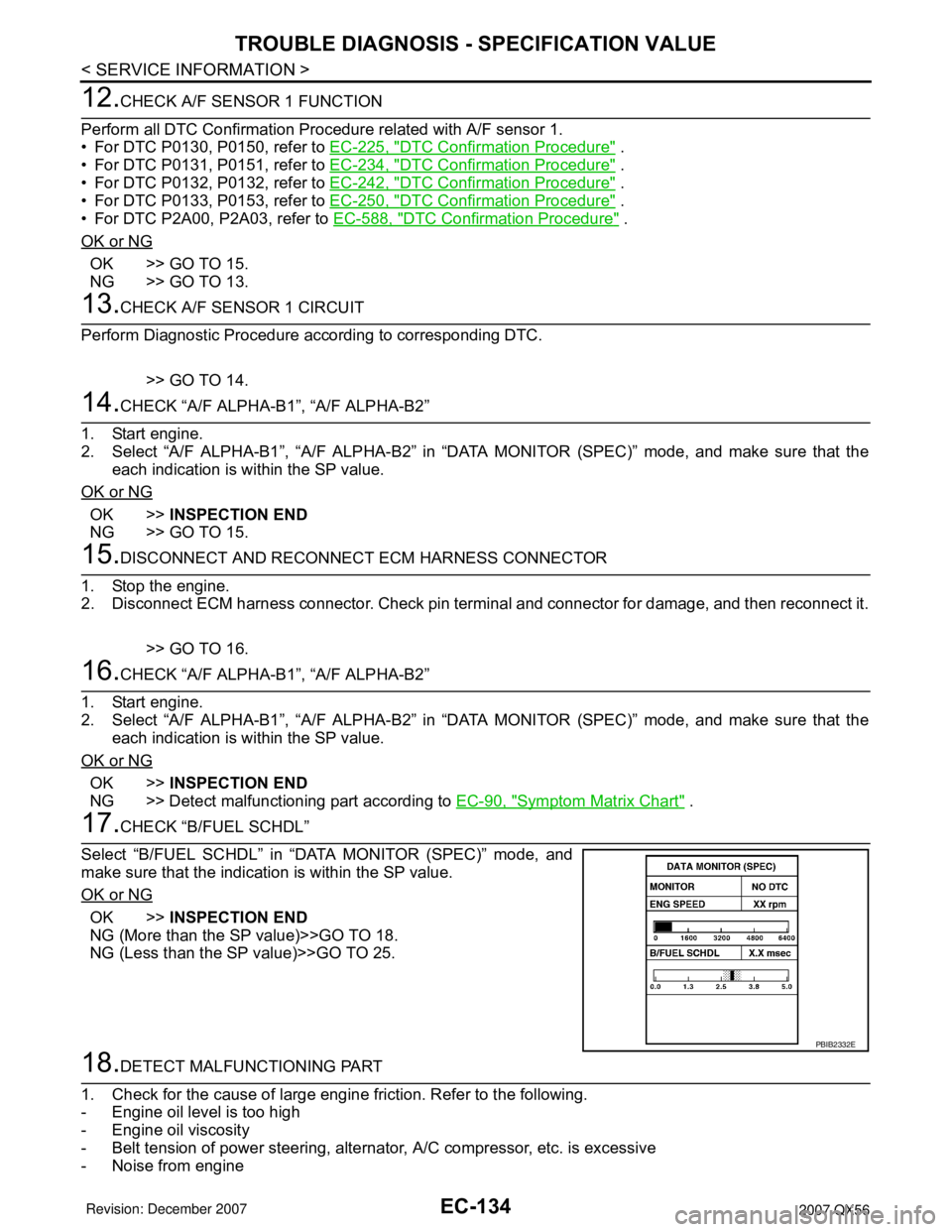
17.CHECK “B/FUEL SCHDL”
Select “B/FUEL SCHDL” in “DATA MONITOR (SPEC)” mode, and
make sure that the indication is within the SP value.
OK or NG
OK >>INSPECTION END
NG (More than the SP value)>>GO TO 18.
NG (Less than the SP value)>>GO TO 25.
18.DETECT MALFUNCTIONING PART
1. Check for the cause of large engine friction. Refer to the following.
- Engine oil level is too high
- Engine oil viscosity
- Belt tension of power steering, alternator, A/C compressor, etc. is excessive
- Noise from engine
PBIB2332E
Page 1218 of 3061
TROUBLE DIAGNOSIS - SPECIFICATION VALUE
EC-135
< SERVICE INFORMATION >
C
D
E
F
G
H
I
J
K
L
MA
EC
N
P O
- Noise from transmission, etc.
2. Check for the cause of insufficient combustion. Refer to the following.
- Valve clearance malfunction
- Intake valve timing control function malfunction
- Camshaft sprocket installation malfunction, etc.
>> Repair or replace malfunctioning part, and then GO TO 30.
19.CHECK INTAKE SYSTEM
Check for the cause of uneven air flow through mass air flow sensor. Refer to the following.
• Crushed air ducts
• Malfunctioning seal of air cleaner element
• Uneven dirt of air cleaner element
• Improper specification of intake air system
OK or NG
OK >> GO TO 21.
NG >> Repair or replace malfunctioning part, and then GO TO 20.
20.CHECK “A/F ALPHA-B1”, “A/F ALPHA-B2”, AND “B/FUEL SCHDL”
Select “A/F ALPHA-B1”, “A/F ALPHA-B2”, and “B/FUEL SCHDL” in “DATA MONITOR (SPEC)” mode, and
make sure that the each indication is within the SP value.
OK or NG
OK >>INSPECTION END
NG (“B/FUEL SCHDL” is more, “A/F ALPHA-B1”, “A/F ALPHA-B2” are less than the SP value)>>GO TO 21.
21.DISCONNECT AND RECONNECT MASS AIR FLOW SENSOR HARNESS CONNECTOR
1. Stop the engine.
2. Disconnect mass air flow sensor harness connector. Check pin terminal and connector for damage and
then reconnect it again.
>> GO TO 22.
22.CHECK “A/F ALPHA-B1”, “A/F ALPHA-B2”
1. Start engine.
2. Select “A/F ALPHA-B1”, “A/F ALPHA-B2” in “DATA MONITOR (SPEC)” mode, and make sure that the
each indication is within the SP value.
OK or NG
OK >> 1. Detect malfunctioning part of mass air flow sensor circuit and repair it. Refer to EC-194 .
2. GO TO 29.
NG >> GO TO 23.
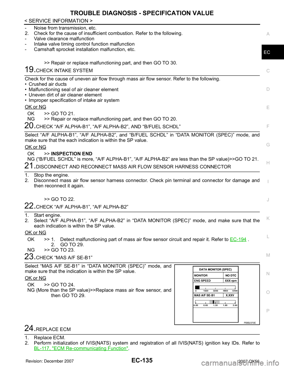
23.CHECK “MAS A/F SE-B1”
Select “MAS A/F SE-B1” in “DATA MONITOR (SPEC)” mode, and
make sure that the indication is within the SP value.
OK or NG
OK >> GO TO 24.
NG (More than the SP value)>>Replace mass air flow sensor, and
then GO TO 29.
24.REPLACE ECM
1. Replace ECM.
2. Perform initialization of IVIS(NATS) system and registration of all IVIS(NATS) ignition key IDs. Refer to
BL-117, "
ECM Re-communicating Function".
PBIB2370E
Page 1228 of 3061
DTC U1000, U1001 CAN COMMUNICATION LINE
EC-145
< SERVICE INFORMATION >
C
D
E
F
G
H
I
J
K
L
MA
EC
N
P O
DTC U1000, U1001 CAN COMMUNICATION LINE
DescriptionINFOID:0000000003531639
CAN (Controller Area Network) is a serial communication line for real time application. It is an on-vehicle mul-
tiplex communication line with high data communication speed and excellent error detection ability. Many elec-
tronic control units are equipped onto a vehicle, and each control unit shares information and links with other
control units during operation (not independent). In CAN communication, control units are connected with 2
communication lines (CAN H line, CAN L line) allowing a high rate of information transmission with less wiring.
Each control unit transmits/receives data but selectively reads required data only.
On Board Diagnosis LogicINFOID:0000000003531640
*1: This self-diagnosis has the one trip detection logic.
*2: The MIL will not light up for this self-diagnosis.
*3: This self-diagnosis has the one or two trip detection logic (Models with ICC)
DTC Confirmation ProcedureINFOID:0000000003531641
1. Turn ignition switch ON and wait at least 3 seconds.
2. Select “DATA MONITOR” mode with CONSULT-II.
3. If 1st trip DTC is detected, go to EC-146, "
Diagnosis Procedure".
DTC No. Trouble diagnosis name DTC detecting condition Possible cause
U1000*
1
1000*1
CAN communication lineWhen ECM is not transmitting or receiving CAN
communication signal of OBD (emission-relat-
ed diagnosis) for 2 seconds or more.• Harness or connectors
(CAN communication line is open or
shorted)
U1001*2*3
1001*2*3
When ECM is not transmitting or receiving CAN
communication signal other than OBD (emis-
sion related diagnosis) for 2 seconds or more.
Page 1234 of 3061
DTC P0011, P0021 IVT CONTROL
EC-151
< SERVICE INFORMATION >
C
D
E
F
G
H
I
J
K
L
MA
EC
N
P O
• If DTC Confirmation Procedure has been previously conducted, always turn ignition switch OFF and wait at
least 10 seconds before conducting the next test.
TESTING CONDITION:
Before performing the following procedure, confirm that battery voltage is between 10V and 16V at
idle.
PROCEDURE FOR MALFUNCTION A
With CONSULT-II
1. Turn ignition switch ON.
2. Select “DATA MONITOR” mode with CONSULT-II.
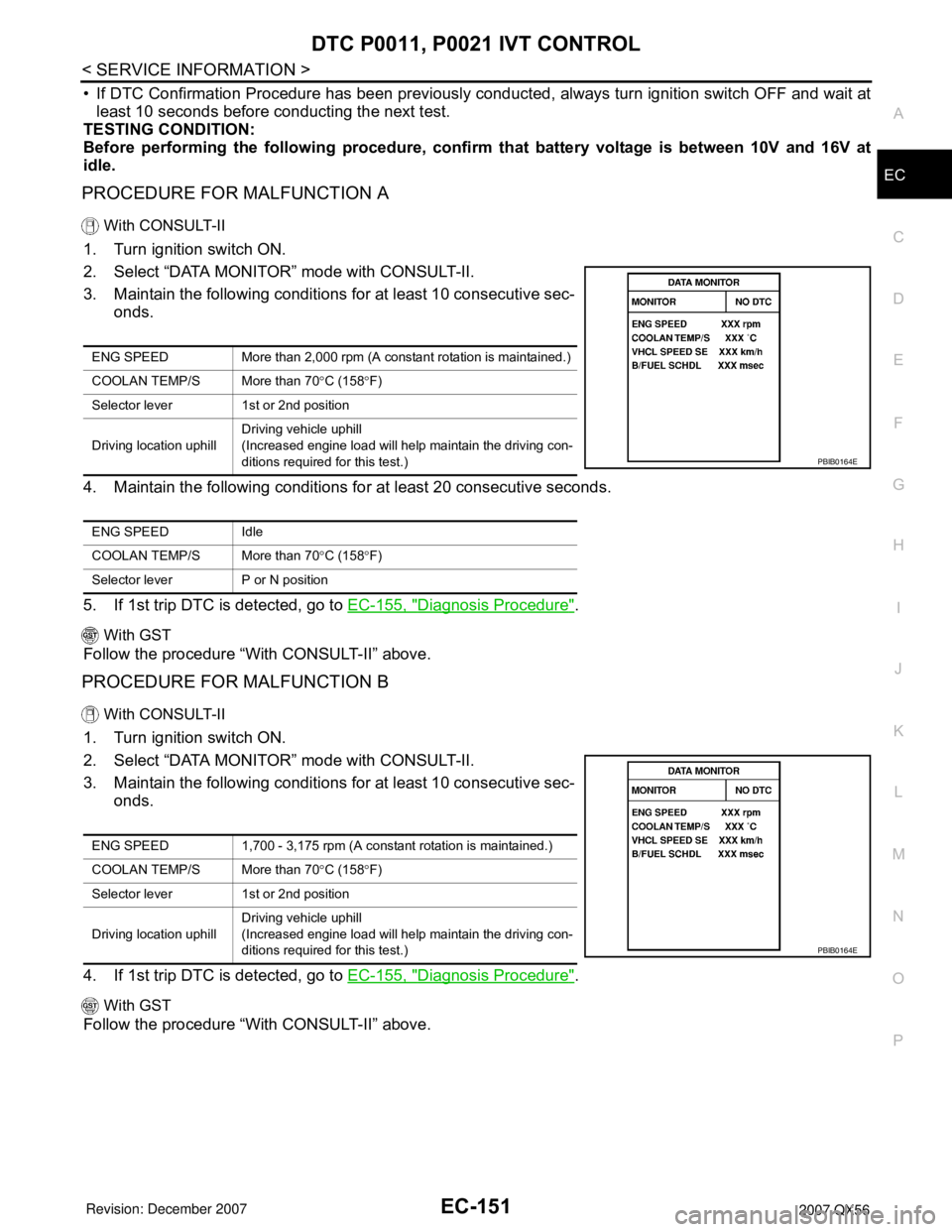
3. Maintain the following conditions for at least 10 consecutive sec-
onds.
4. Maintain the following conditions for at least 20 consecutive seconds.
5. If 1st trip DTC is detected, go to EC-155, "
Diagnosis Procedure".
With GST
Follow the procedure “With CONSULT-II” above.
PROCEDURE FOR MALFUNCTION B
With CONSULT-II
1. Turn ignition switch ON.
2. Select “DATA MONITOR” mode with CONSULT-II.
3. Maintain the following conditions for at least 10 consecutive sec-
onds.
4. If 1st trip DTC is detected, go to EC-155, "
Diagnosis Procedure".
With GST
Follow the procedure “With CONSULT-II” above.
ENG SPEED More than 2,000 rpm (A constant rotation is maintained.)
COOLAN TEMP/S More than 70°C (158°F)
Selector lever 1st or 2nd position
Driving location uphillDriving vehicle uphill
(Increased engine load will help maintain the driving con-
ditions required for this test.)
ENG SPEED Idle
COOLAN TEMP/S More than 70°C (158°F)
Selector lever P or N position
PBIB0164E
ENG SPEED 1,700 - 3,175 rpm (A constant rotation is maintained.)
COOLAN TEMP/S More than 70°C (158°F)
Selector lever 1st or 2nd position
Driving location uphillDriving vehicle uphill
(Increased engine load will help maintain the driving con-
ditions required for this test.)
PBIB0164E