2007 INFINITI QX56 ECO mode
[x] Cancel search: ECO modePage 2914 of 3061
TF-92
< SERVICE INFORMATION >
TROUBLE DIAGNOSIS FOR SYSTEM
Perform the self-diagnosis, after driving a vehicle for a while.
OK or NG
OK >> Inspection End.
NG >> Replace transfer control unit. Refer to TF-115, "
Removal and Installation".
COMPONENT INSPECTION
1. Turn ignition switch “OFF”. (Stay for at least 5 seconds.)
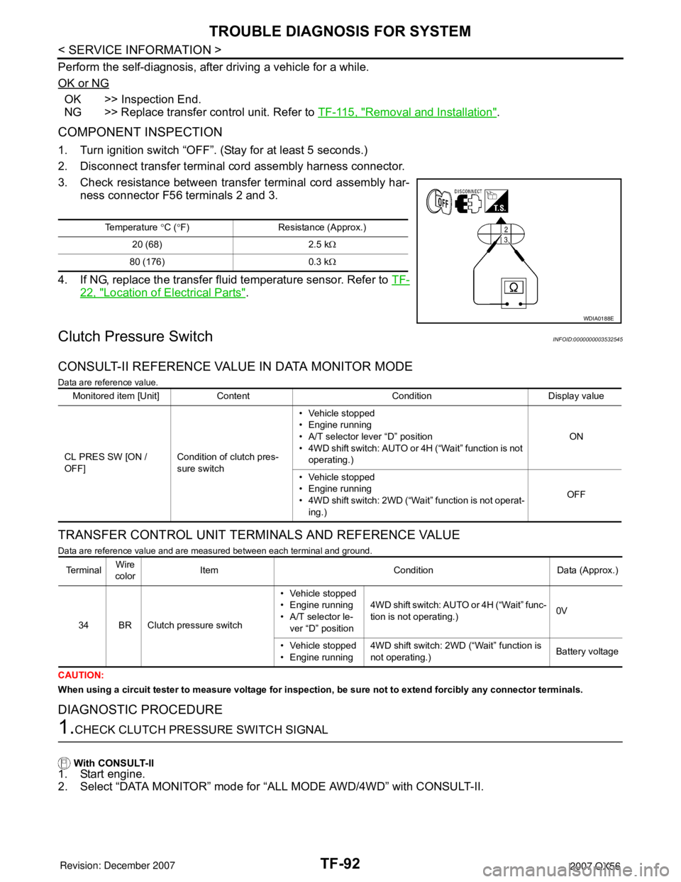
2. Disconnect transfer terminal cord assembly harness connector.
3. Check resistance between transfer terminal cord assembly har-
ness connector F56 terminals 2 and 3.
4. If NG, replace the transfer fluid temperature sensor. Refer to TF-
22, "Location of Electrical Parts".
Clutch Pressure SwitchINFOID:0000000003532545
CONSULT-II REFERENCE VALUE IN DATA MONITOR MODE
Data are reference value.
TRANSFER CONTROL UNIT TERMINALS AND REFERENCE VALUE
Data are reference value and are measured between each terminal and ground.
CAUTION:
When using a circuit tester to measure voltage for inspection, be sure not to extend forcibly any connector terminals.
DIAGNOSTIC PROCEDURE
1.CHECK CLUTCH PRESSURE SWITCH SIGNAL
With CONSULT-II
1. Start engine.
2. Select “DATA MONITOR” mode for “ALL MODE AWD/4WD” with CONSULT-II.
Temperature °C (°F) Resistance (Approx.)
20 (68) 2.5 kΩ
80 (176) 0.3 kΩ
WDIA0188E
Monitored item [Unit] Content Condition Display value
CL PRES SW [ON /
OFF]Condition of clutch pres-
sure switch• Vehicle stopped
• Engine running
• A/T selector lever “D” position
• 4WD shift switch: AUTO or 4H (“Wait” function is not
operating.)ON
• Vehicle stopped
• Engine running
• 4WD shift switch: 2WD (“Wait” function is not operat-
ing.)OFF
Te r m i n a lWire
colorItem Condition Data (Approx.)
34 BR Clutch pressure switch• Vehicle stopped
• Engine running
• A/T selector le-
ver “D” position4WD shift switch: AUTO or 4H (“Wait” func-
tion is not operating.)0V
• Vehicle stopped
• Engine running4WD shift switch: 2WD (“Wait” function is
not operating.)Battery voltage
Page 2916 of 3061
TF-94
< SERVICE INFORMATION >
TROUBLE DIAGNOSIS FOR SYSTEM
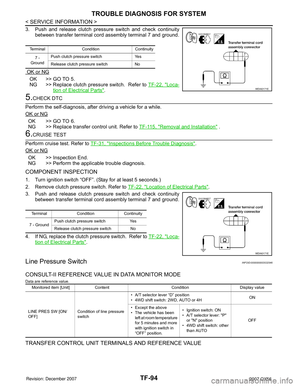
3. Push and release clutch pressure switch and check continuity
between transfer terminal cord assembly terminal 7 and ground.
OK or NG
OK >> GO TO 5.
NG >> Replace clutch pressure switch. Refer to TF-22, "
Loca-
tion of Electrical Parts".
5.CHECK DTC
Perform the self-diagnosis, after driving a vehicle for a while.
OK or NG
OK >> GO TO 6.
NG >> Replace transfer control unit. Refer to TF-115, "
Removal and Installation" .
6.CRUISE TEST
Perform cruise test. Refer to TF-31, "
Inspections Before Trouble Diagnosis".
OK or NG
OK >> Inspection End.
NG >> Perform the applicable trouble diagnosis.
COMPONENT INSPECTION
1. Turn ignition switch “OFF”. (Stay for at least 5 seconds.)
2. Remove clutch pressure switch. Refer to TF-22, "
Location of Electrical Parts".
3. Push and release clutch pressure switch and check continuity
between transfer terminal cord assembly terminal 7 and ground.
4. If NG, replace the clutch pressure switch. Refer to TF-22, "
Loca-
tion of Electrical Parts".
Line Pressure SwitchINFOID:0000000003532546
CONSULT-II REFERENCE VALUE IN DATA MONITOR MODE
Data are reference value.
TRANSFER CONTROL UNIT TERMINALS AND REFERENCE VALUE
Terminal Condition Continuity
7 -
GroundPush clutch pressure switch Yes
Release clutch pressure switch No
WDIA0171E
Terminal Condition Continuity
7 - GroundPush clutch pressure switch Yes
Release clutch pressure switch No
WDIA0171E
Monitored item [Unit] Content Condition Display value
LINE PRES SW [ON/
OFF]Condition of line pressure
switch• A/T selector lever “D” position
• 4WD shift switch: 2WD, AUTO or 4HON
• Except the above
• The vehicle has been
left at room temperature
for 5 minutes and more
with ignition switch in
“OFF” position.• Ignition switch: ON
• A/T selector lever: "P"
or "N" position
• 4WD shift switch: other
than AUTOOFF
Page 2917 of 3061
TROUBLE DIAGNOSIS FOR SYSTEM
TF-95
< SERVICE INFORMATION >
C
E
F
G
H
I
J
K
L
MA
B
TF
N
O
P
Data are reference value and are measured between each terminal and ground.
CAUTION:
When using a circuit tester to measure voltage for inspection, be sure not to extend forcibly any connector terminals.
DIAGNOSTIC PROCEDURE
1.CHECK LINE PRESSURE SWITCH SIGNAL
With CONSULT-II
1. Start engine.
2. Select “DATA MONITOR” mode for “ALL MODE AWD/4WD” with CONSULT-II.
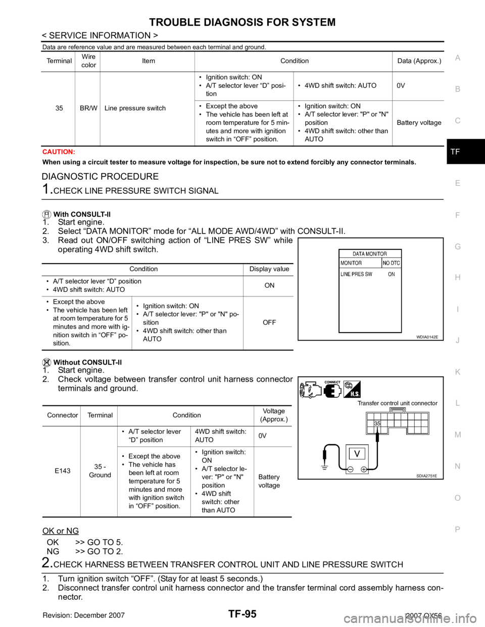
3. Read out ON/OFF switching action of “LINE PRES SW” while
operating 4WD shift switch.
Without CONSULT-II
1. Start engine.
2. Check voltage between transfer control unit harness connector
terminals and ground.
OK or NG
OK >> GO TO 5.
NG >> GO TO 2.
2.CHECK HARNESS BETWEEN TRANSFER CONTROL UNIT AND LINE PRESSURE SWITCH
1. Turn ignition switch “OFF”. (Stay for at least 5 seconds.)
2. Disconnect transfer control unit harness connector and the transfer terminal cord assembly harness con-
nector.
Te r m i n a lWire
colorItem Condition Data (Approx.)
35 BR/W Line pressure switch• Ignition switch: ON
• A/T selector lever “D” posi-
tion• 4WD shift switch: AUTO 0V
• Except the above
• The vehicle has been left at
room temperature for 5 min-
utes and more with ignition
switch in “OFF” position.• Ignition switch: ON
• A/T selector lever: "P" or "N"
position
• 4WD shift switch: other than
AUTOBattery voltage
Condition Display value
• A/T selector lever “D” position
• 4WD shift switch: AUTOON
• Except the above
• The vehicle has been left
at room temperature for 5
minutes and more with ig-
nition switch in “OFF” po-
sition.• Ignition switch: ON
• A/T selector lever: "P" or "N" po-
sition
• 4WD shift switch: other than
AUTOOFF
Connector Terminal ConditionVoltage
(Approx.)
E14335 -
Ground• A/T selector lever
“D” position4WD shift switch:
AUTO0V
• Except the above
• The vehicle has
been left at room
temperature for 5
minutes and more
with ignition switch
in “OFF” position.• Ignition switch:
ON
• A/T selector le-
ver: "P" or "N"
position
• 4WD shift
switch: other
than AUTOBattery
voltage
WDIA0142E
SDIA2751E
Page 3002 of 3061
TROUBLE DIAGNOSIS
WT-13
< SERVICE INFORMATION >
C
D
F
G
H
I
J
K
L
MA
B
WT
N
O
P
This procedure must be done after replacement of a low tire pressure warning transmitter or BCM.
New replacement transmitters are provided "asleep" and must first be "woken up" using Transmitter
Activation Tool J-45295 before ID registration can be performed.
1. Connect CONSULT-II. Refer to GI-36, "
CONSULT-II Start Procedure".
2. Select “AIR PRESSURE MONITOR” on "SELECT TEST ITEM" screen.
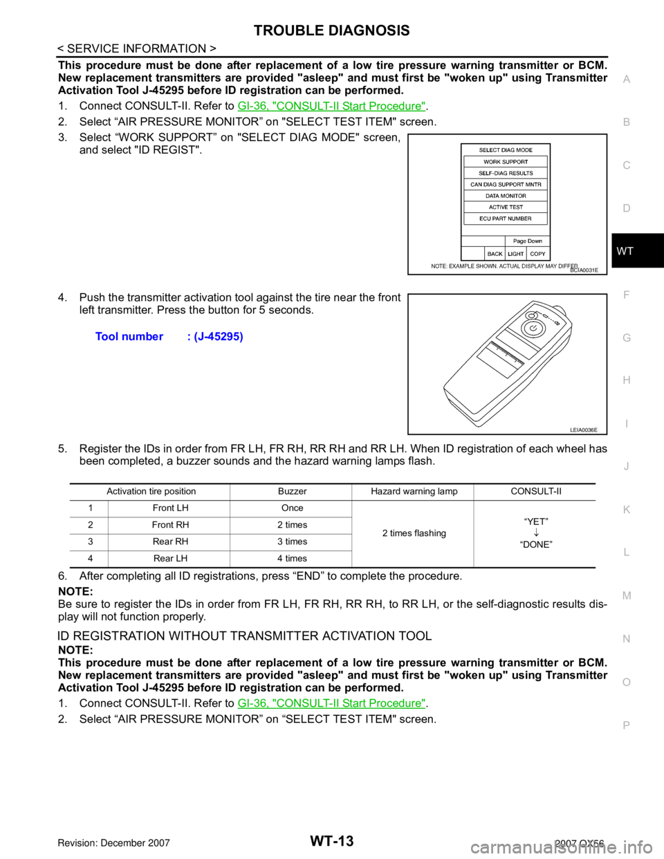
3. Select “WORK SUPPORT” on "SELECT DIAG MODE" screen,
and select "ID REGIST".
4. Push the transmitter activation tool against the tire near the front
left transmitter. Press the button for 5 seconds.
5. Register the IDs in order from FR LH, FR RH, RR RH and RR LH. When ID registration of each wheel has
been completed, a buzzer sounds and the hazard warning lamps flash.
6. After completing all ID registrations, press “END” to complete the procedure.
NOTE:
Be sure to register the IDs in order from FR LH, FR RH, RR RH, to RR LH, or the self-diagnostic results dis-
play will not function properly.
ID REGISTRATION WITHOUT TRANSMITTER ACTIVATION TOOL
NOTE:
This procedure must be done after replacement of a low tire pressure warning transmitter or BCM.
New replacement transmitters are provided "asleep" and must first be "woken up" using Transmitter
Activation Tool J-45295 before ID registration can be performed.
1. Connect CONSULT-II. Refer to GI-36, "
CONSULT-II Start Procedure".
2. Select “AIR PRESSURE MONITOR” on “SELECT TEST ITEM" screen.
BCIA0031E
Tool number : (J-45295)
LEIA0036E
Activation tire position Buzzer Hazard warning lamp CONSULT-II
1 Front LH Once
2 times flashing“YET”
↓
“DONE” 2 Front RH 2 times
3 Rear RH 3 times
4 Rear LH 4 times
Page 3003 of 3061
WT-14
< SERVICE INFORMATION >
TROUBLE DIAGNOSIS
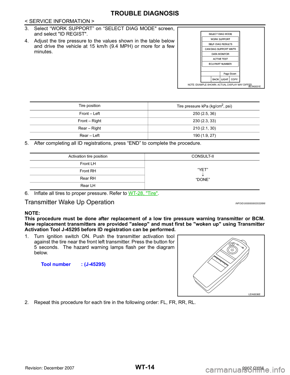
3. Select “WORK SUPPORT” on “SELECT DIAG MODE" screen,
and select "ID REGIST".
4. Adjust the tire pressure to the values shown in the table below
and drive the vehicle at 15 km/h (9.4 MPH) or more for a few
minutes.
5. After completing all ID registrations, press “END” to complete the procedure.
6. Inflate all tires to proper pressure. Refer to WT-28, "
Tire".
Transmitter Wake Up OperationINFOID:0000000003532698
NOTE:
This procedure must be done after replacement of a low tire pressure warning transmitter or BCM.
New replacement transmitters are provided "asleep" and must first be "woken up" using Transmitter
Activation Tool J-45295 before ID registration can be performed.
1. Turn ignition switch ON. Push the transmitter activation tool
against the tire near the front left transmitter. Press the button for
5 seconds. The hazard warning lamps flash per the diagram
below.
2. Repeat this procedure for each tire in the following order: FL, FR, RR, RL.
BCIA0031E
Tire position
Tire pressure kPa (kg/cm2, psi)
Front – Left 250 (2.5, 36)
Front – Right 230 (2.3, 33)
Rear – Right 210 (2.1, 30)
Rear – Left 190 (1.9, 27)
Activation tire position CONSULT-II
Front LH
“YET”
↓
“DONE” Front RH
Rear RH
Rear LH
Tool number : (J-45295)
LEIA0036E
Page 3004 of 3061
TROUBLE DIAGNOSIS
WT-15
< SERVICE INFORMATION >
C
D
F
G
H
I
J
K
L
MA
B
WT
N
O
P
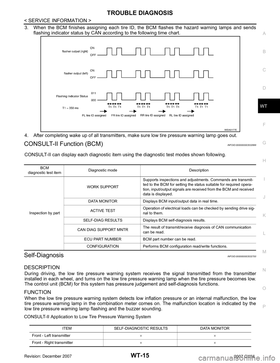
3. When the BCM finishes assigning each tire ID, the BCM flashes the hazard warning lamps and sends
flashing indicator status by CAN according to the following time chart.
4. After completing wake up of all transmitters, make sure low tire pressure warning lamp goes out.
CONSULT-II Function (BCM)INFOID:0000000003532699
CONSULT-II can display each diagnostic item using the diagnostic test modes shown following.
Self-DiagnosisINFOID:0000000003532700
DESCRIPTION
During driving, the low tire pressure warning system receives the signal transmitted from the transmitter
installed in each wheel, and turns on the low tire pressure warning lamp when the tire pressure becomes low.
The control unit (BCM) for this system has pressure judgement and self-diagnosis functions.
FUNCTION
When the low tire pressure warning system detects low inflation pressure or an internal malfunction, the low
tire pressure warning lamp in the combination meter comes on. The malfunction location is indicated by the
low tire pressure warning lamp flashing and the buzzer sounding.
CONSULT-II Application to Low Tire Pressure Warning System
WEIA0177E
BCM
diagnostic test itemDiagnostic mode Description
Inspection by partWORK SUPPORTSupports inspections and adjustments. Commands are transmit-
ted to the BCM for setting the status suitable for required opera-
tion, input/output signals are received from the BCM and received
data is displayed.
DATA MONITOR Displays BCM input/output data in real time.
ACTIVE TESTOperation of electrical loads can be checked by sending drive sig-
nal to them.
SELF-DIAG RESULTS Displays BCM self-diagnosis results.
CAN DIAG SUPPORT MNTRThe result of transmit/receive diagnosis of CAN communication
can be read.
ECU PART NUMBER BCM part number can be read.
CONFIGURATION Performs BCM configuration read/write functions.
ITEM SELF-DIAGNOSTIC RESULTS DATA MONITOR
Front - Left transmitter××
Front - Right transmitter××
Page 3029 of 3061

WW-12
< SERVICE INFORMATION >
FRONT WIPER AND WASHER SYSTEM
ACTIVE TEST
Display Item List
CONSULT-II Function (IPDM E/R)INFOID:0000000003533561
CONSULT-II can display each diagnostic item using the diagnostic test modes shown following.
CONSULT-II START PROCEDURE
Refer to GI-36, "CONSULT-II Start Procedure".
DATA MONITOR
All Items, Main Items, Select Item Menu
NOTE:
Perform monitoring of IPDM E/R data with the ignition switch ON. When the ignition switch is at ACC, the dis-
play may not be correct.
ACTIVE TEST
Display Item List
FR WASHER SW "ON/OFF"Displays "Front Washer Switch (ON)/Other (OFF)" status as judged from wiper switch
signal.
INT VOLUME (1 - 7)Displays intermittent operation dial position setting (1 - 7) as judged from wiper switch
signal.
FR WIPER STOP "ON/OFF" Displays "Stopped (ON)/Operating (OFF)" status as judged from the auto-stop signal.
VEHICLE SPEED "0.0 km/h" Displays vehicle speed as received from CAN communication. Monitor item name
"OPERATION OR UNIT"Contents
Te s t i t e mDisplay on CONSULT-II
screenDescription
Front wiper HI output FR WIPER (HI) Front wiper HI can be operated by any ON-OFF operation.
Front wiper LO output FR WIPER (LO) Front wiper LO can be operated by any ON-OFF operation.
Front wiper INT output FR WIPER (INT) Front wiper INT can be operated by any ON-OFF operation.
IPDM E/R diagnostic Mode Description
SELF-DIAG RESULTS Displays IPDM E/R self-diagnosis results.
DATA MONITOR Displays IPDM E/R input/output data in real time.
CAN DIAG SUPPORT MNTR The result of transmit/receive diagnosis of CAN communication can be read.
ACTIVE TEST Operation of electrical loads can be checked by sending drive signal to them.
ALL SIGNALS Monitors all the items.
MAIN SIGNALS Monitors predetermined items.
SELECTION FROM MENU Selects and monitors the individual item selected.
Item nameCONSULT-II
screen displayDisplay or unitMonitor item selection
Description
ALL
SIGNALSMAIN
SIGNALSSELECTION
FROM MENU
Front wiper re-
questFR WIP REQ STOP/1LO/LO/HI x x x Signal status input from BCM.
Wiper auto stop WIP AUTO STOP ACT P/STOP P x x x Output status of IPDM E/R.
Wiper protection WIP PROT OFF/LS/HS/BLOCK x x x Control status of IPDM E/R.