2007 INFINITI QX56 ECO mode
[x] Cancel search: ECO modePage 2606 of 3061
RSU-16
< SERVICE INFORMATION >
TROUBLE DIAGNOSIS FOR SELF-DIAGNOSTIC ITEMS
The "COMPRESSOR" active test will remain ON until it is turned off using CONSULT-II. Allowing
the compressor to run for an extended period of time may cause damage to air suspension sys-
tem components due to excessive pressure in the air suspension system.
3. Return the rear load leveling air suspension system to normal operating mode.
4. Check self-diagnostic results.
Is code C1805 displayed again?
YES >> GO TO 3.
NO >> Inspection End.
3.CONNECTOR INSPECTION
1. Disconnect suspension control unit connector B3 and suspension air compressor C9.
2. Check the terminals for deformation, disconnection, looseness or damage.
OK or NG
OK >> If code C1805 was retrieved during self-diagnosis, GO TO 4. If code C1803 was retrieved during
self-diagnosis, GO TO 6.
NG >> Repair or replace as necessary.
4.AIR HOSE INSPECTION
Inspect for pinched or damaged air hoses between the suspension air reservoir and each load leveling rear air
suspension shock absorber.
OK or NG
OK >> GO TO 5.
NG >> Repair or replace as necessary.
5.EXHAUST VALVE SOLENOID INSPECTION
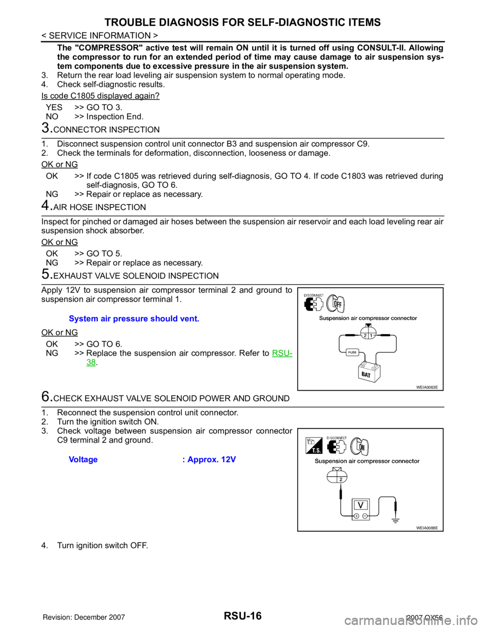
Apply 12V to suspension air compressor terminal 2 and ground to
suspension air compressor terminal 1.
OK or NG
OK >> GO TO 6.
NG >> Replace the suspension air compressor. Refer to RSU-
38.
6.CHECK EXHAUST VALVE SOLENOID POWER AND GROUND
1. Reconnect the suspension control unit connector.
2. Turn the ignition switch ON.
3. Check voltage between suspension air compressor connector
C9 terminal 2 and ground.
4. Turn ignition switch OFF.System air pressure should vent.
WEIA0063E
Voltage : Approx. 12V
WEIA0088E
Page 2607 of 3061
TROUBLE DIAGNOSIS FOR SELF-DIAGNOSTIC ITEMS
RSU-17
< SERVICE INFORMATION >
C
D
F
G
H
I
J
K
L
MA
B
RSU
N
O
P
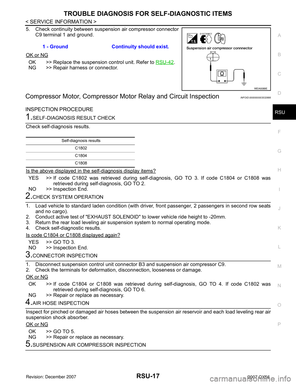
5. Check continuity between suspension air compressor connector
C9 terminal 1 and ground.
OK or NG
OK >> Replace the suspension control unit. Refer to RSU-42.
NG >> Repair harness or connector.
Compressor Motor, Compressor Motor Relay and Circuit InspectionINFOID:0000000003532666
INSPECTION PROCEDURE
1.SELF-DIAGNOSIS RESULT CHECK
Check self-diagnosis results.
Is the above displayed in the self-diagnosis display items?
YES >> If code C1802 was retrieved during self-diagnosis, GO TO 3. If code C1804 or C1808 was
retrieved during self-diagnosis, GO TO 2.
NO >> Inspection End.
2.CHECK SYSTEM OPERATION
1. Load vehicle to standard laden condition (with driver, front passenger, 2 passengers in second row seats
and no cargo).
2. Conduct active test of "EXHAUST SOLENOID" to lower vehicle ride height to -20mm.
3. Return the rear load leveling air suspension system to normal operating mode.
4. Check self-diagnostic results.
Is code C1804 or C1808 displayed again?
YES >> GO TO 3.
NO >> Inspection End.
3.CONNECTOR INSPECTION
1. Disconnect suspension control unit connector B3 and suspension air compressor C9.
2. Check the terminals for deformation, disconnection, looseness or damage.
OK or NG
OK >> If code C1804 or C1808 was retrieved during self-diagnosis, GO TO 4. If code C1802 was
retrieved during self-diagnosis, GO TO 6.
NG >> Repair or replace as necessary.
4.AIR HOSE INSPECTION
Inspect for pinched or damaged air hoses between the suspension air reservoir and each load leveling rear air
suspension shock absorber.
OK or NG
OK >> GO TO 5.
NG >> Repair or replace as necessary.
5.SUSPENSION AIR COMPRESSOR INSPECTION1 - Ground Continuity should exist.
WEIA0089E
Self-diagnosis results
C1802
C1804
C1808
Page 2684 of 3061

SE-12
< SERVICE INFORMATION >
AUTOMATIC DRIVE POSITIONER
NOTE:
• Disconnecting the battery erases the stored memory.
• After connecting the battery, insert the key into the ignition cylinder and turn the front door switch LH ON (open)→OFF (close)→ON
(open), the entry/exiting function becomes possible.
• After Exiting operation is carried out, return operation can be operated.
NOTE:
During automatic operation, if the ignition switch is turned ON→START, the automatic operation is suspended. When the ignition switch
returns to ON, it resumes.
FA I L - S A F E M O D E
When any manual and automatic operations are not performed, if any motor operations of seats or pedals are
detected for T2 or more, status is judged “Output error”.
CANCEL OF FAIL-SAFE MODE
The mode is cancelled when the A/T selector lever is shifted to P position from any other position.
NOTE:
The front seat LH position and pedal adjustment functions (see the following table) operate simultaneously in
the order of priority.
*: In conjunction with sliding the seat, the door mirrors are positioned.Function Description
Memory operation The front seat LH, steering wheel, pedals (accelerator, brake) and door mirrors move
to the stored driving position by pushing seat memory switch (1 or 2).
Entry/exit-
ing functionExiting operation At exit, the seat moves backward and the steering wheel raises. (Exiting position)
Entry operationAt entry, the seat and steering wheel return from exiting position to the previous driving
position before the exiting operation.
Keyfob interlock operationPerform memory operation, turnout operation and return operation by pressing keyfob
unlock button.
Auto operation temporary stop
conditions.When ignition switch is turned to START during seat memory switch operation and return
operation, seat memory switch operation and return operation is stopped.
Auto operation stop conditions.• When the vehicle speed becomes 7 km/h (4 MPH) or higher (memory switch operation
and entry operation).
• When the setting switch, seat memory switch 1, or 2 are pressed.
• When A/T selector lever is in any position other than P.
• When the door mirror remote control switch is operated (when ignition switch turned to
ON).
• When power seat switch turned ON.
• When pedal adjusting switch turned ON.
• When front seat sliding entry/exiting setting is OFF (entry/exiting operation).
OPERATED PORTION T2
Seat sliding Approx. 0.1 sec.
Seat reclining Same as above
Seat lifting (Front) Same as above
Seat lifting (Rear) Same as above
Steering wheel Same as above
Pedal adjust Same as above
Priority Function Priority Function
1 Seat sliding, (door mirror LH/RH)* 4 Seat reclining
2 Pedal 5 Seat lifter-FR
3 Steering wheel 6 Seat lifter-RR
Page 2704 of 3061
SE-32
< SERVICE INFORMATION >
AUTOMATIC DRIVE POSITIONER
1. Turn ignition switch OFF.
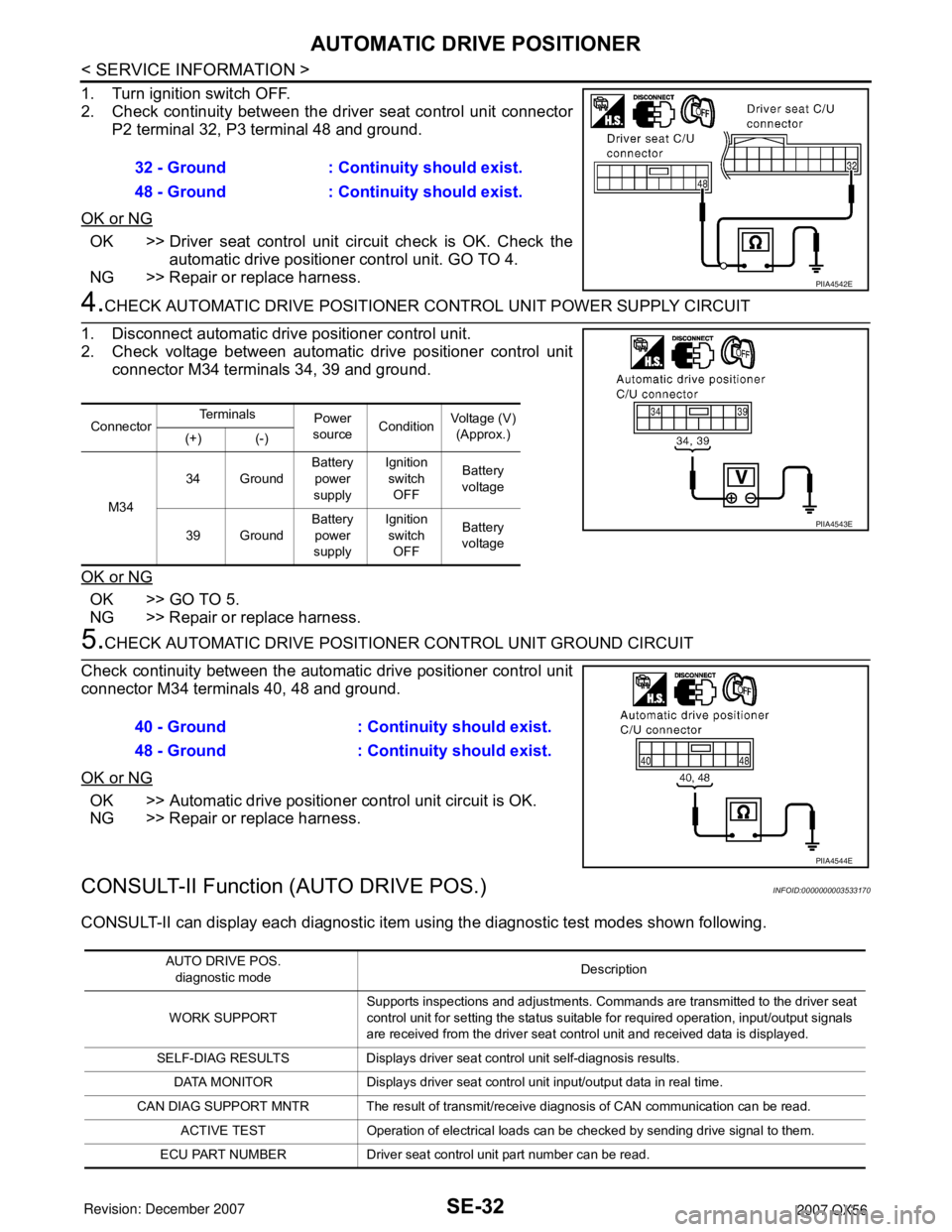
2. Check continuity between the driver seat control unit connector
P2 terminal 32, P3 terminal 48 and ground.
OK or NG
OK >> Driver seat control unit circuit check is OK. Check the
automatic drive positioner control unit. GO TO 4.
NG >> Repair or replace harness.
4.CHECK AUTOMATIC DRIVE POSITIONER CONTROL UNIT POWER SUPPLY CIRCUIT
1. Disconnect automatic drive positioner control unit.
2. Check voltage between automatic drive positioner control unit
connector M34 terminals 34, 39 and ground.
OK or NG
OK >> GO TO 5.
NG >> Repair or replace harness.
5.CHECK AUTOMATIC DRIVE POSITIONER CONTROL UNIT GROUND CIRCUIT
Check continuity between the automatic drive positioner control unit
connector M34 terminals 40, 48 and ground.
OK or NG
OK >> Automatic drive positioner control unit circuit is OK.
NG >> Repair or replace harness.
CONSULT-II Function (AUTO DRIVE POS.)INFOID:0000000003533170
CONSULT-II can display each diagnostic item using the diagnostic test modes shown following. 32 - Ground : Continuity should exist.
48 - Ground : Continuity should exist.
PIIA4542E
ConnectorTe r m i n a l s
Power
sourceConditionVoltage (V)
(Approx.)
(+) (-)
M3434 GroundBattery
power
supplyIgnition
switch
OFFBattery
voltage
39 GroundBattery
power
supplyIgnition
switch
OFFBattery
voltage
PIIA4543E
40 - Ground : Continuity should exist.
48 - Ground : Continuity should exist.
PIIA4544E
AUTO DRIVE POS.
diagnostic modeDescription
WORK SUPPORTSupports inspections and adjustments. Commands are transmitted to the driver seat
control unit for setting the status suitable for required operation, input/output signals
are received from the driver seat control unit and received data is displayed.
SELF-DIAG RESULTS Displays driver seat control unit self-diagnosis results.
DATA MONITOR Displays driver seat control unit input/output data in real time.
CAN DIAG SUPPORT MNTR The result of transmit/receive diagnosis of CAN communication can be read.
ACTIVE TEST Operation of electrical loads can be checked by sending drive signal to them.
ECU PART NUMBER Driver seat control unit part number can be read.
Page 2788 of 3061
SRS-18
< SERVICE INFORMATION >
TROUBLE DIAGNOSIS
CONSULT-II Function
INFOID:0000000003532866
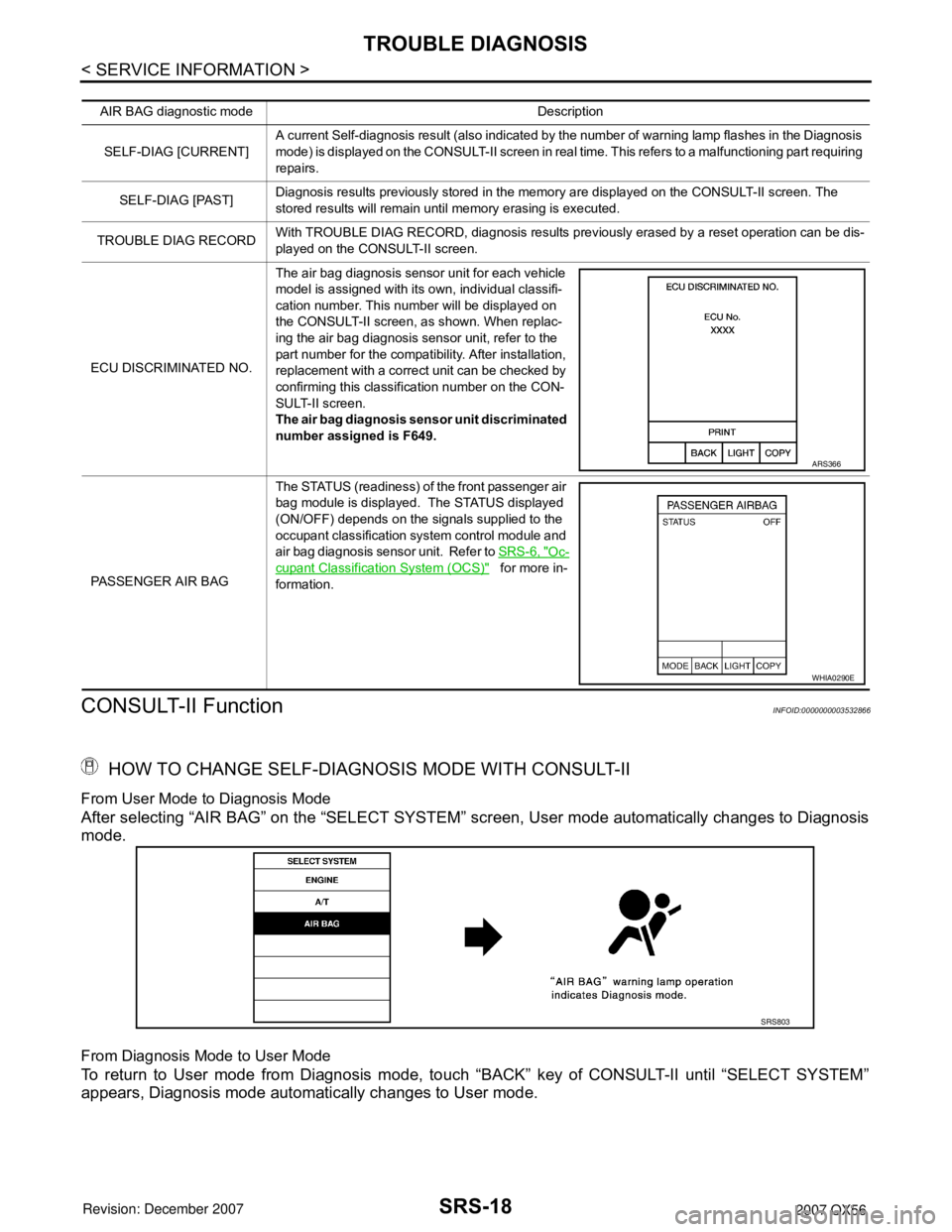
HOW TO CHANGE SELF-DIAGNOSIS MODE WITH CONSULT-II
From User Mode to Diagnosis Mode
After selecting “AIR BAG” on the “SELECT SYSTEM” screen, User mode automatically changes to Diagnosis
mode.
From Diagnosis Mode to User Mode
To return to User mode from Diagnosis mode, touch “BACK” key of CONSULT-II until “SELECT SYSTEM”
appears, Diagnosis mode automatically changes to User mode.
AIR BAG diagnostic mode Description
SELF-DIAG [CURRENT]A current Self-diagnosis result (also indicated by the number of warning lamp flashes in the Diagnosis
mode) is displayed on the CONSULT-II screen in real time. This refers to a malfunctioning part requiring
repairs.
SELF-DIAG [PAST]Diagnosis results previously stored in the memory are displayed on the CONSULT-II screen. The
stored results will remain until memory erasing is executed.
TROUBLE DIAG RECORDWith TROUBLE DIAG RECORD, diagnosis results previously erased by a reset operation can be dis-
played on the CONSULT-II screen.
ECU DISCRIMINATED NO.The air bag diagnosis sensor unit for each vehicle
model is assigned with its own, individual classifi-
cation number. This number will be displayed on
the CONSULT-II screen, as shown. When replac-
ing the air bag diagnosis sensor unit, refer to the
part number for the compatibility. After installation,
replacement with a correct unit can be checked by
confirming this classification number on the CON-
SULT-II screen.
The air bag diagnosis sensor unit discriminated
number assigned is F649.
PASSENGER AIR BAGThe STATUS (readiness) of the front passenger air
bag module is displayed. The STATUS displayed
(ON/OFF) depends on the signals supplied to the
occupant classification system control module and
air bag diagnosis sensor unit. Refer to SRS-6, "
Oc-
cupant Classification System (OCS)" for more in-
formation.
ARS366
WHIA0290E
SRS803
Page 2789 of 3061
![INFINITI QX56 2007 Factory Service Manual TROUBLE DIAGNOSIS
SRS-19
< SERVICE INFORMATION >
C
D
E
F
G
I
J
K
L
MA
B
SRS
N
O
P
HOW TO ERASE SELF-DIAGNOSIS RESULTS
• “SELF-DIAG [CURRENT]”
A current self-diagnosis result is displayed on the INFINITI QX56 2007 Factory Service Manual TROUBLE DIAGNOSIS
SRS-19
< SERVICE INFORMATION >
C
D
E
F
G
I
J
K
L
MA
B
SRS
N
O
P
HOW TO ERASE SELF-DIAGNOSIS RESULTS
• “SELF-DIAG [CURRENT]”
A current self-diagnosis result is displayed on the](/manual-img/42/57029/w960_57029-2788.png)
TROUBLE DIAGNOSIS
SRS-19
< SERVICE INFORMATION >
C
D
E
F
G
I
J
K
L
MA
B
SRS
N
O
P
HOW TO ERASE SELF-DIAGNOSIS RESULTS
• “SELF-DIAG [CURRENT]”
A current self-diagnosis result is displayed on the CONSULT-II
screen in real time.
After the malfunction is repaired completely, no malfunction is
detected on “SELF-DIAG [CURRENT]”.
• “SELF-DIAG [PAST]”
Return to the “SELF-DIAG [CURRENT]” CONSULT-II screen by
touching “BACK” key of CONSULT-II and select “SELF-DIAG
[PAST]” in SELECT DIAG MODE. Touch “ERASE” in “SELF-DIAG
[PAST]” mode.
NOTE:
If the memory of the malfunction in “SELF-DIAG [PAST]” is
not erased, the User mode will continue to show the system
malfunction by the operation of the warning lamp even if the
malfunction is repaired completely.
• “TROUBLE DIAG RECORD”
The memory of “TROUBLE DIAG RECORD” cannot be erased.
Self-Diagnosis Function (Without CONSULT-II)INFOID:0000000003532867
• The reading of these results is accomplished using one of two modes — “User mode” and “Diagnosis
mode”.
• After a malfunction is repaired, turn the ignition switch OFF for at least one second, then back ON. Diagnosis
mode returns to the User mode. At that time, the self-diagnostic result is cleared.
SRS804
SRS701
SRS702
Page 2790 of 3061
SRS-20
< SERVICE INFORMATION >
TROUBLE DIAGNOSIS
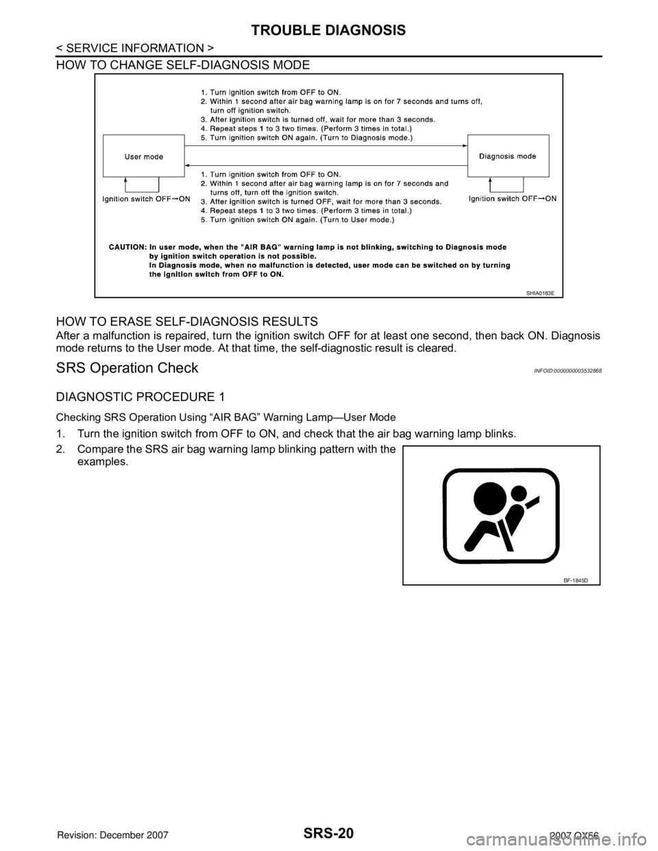
HOW TO CHANGE SELF-DIAGNOSIS MODE
HOW TO ERASE SELF-DIAGNOSIS RESULTS
After a malfunction is repaired, turn the ignition switch OFF for at least one second, then back ON. Diagnosis
mode returns to the User mode. At that time, the self-diagnostic result is cleared.
SRS Operation CheckINFOID:0000000003532868
DIAGNOSTIC PROCEDURE 1
Checking SRS Operation Using “AIR BAG” Warning Lamp—User Mode
1. Turn the ignition switch from OFF to ON, and check that the air bag warning lamp blinks.
2. Compare the SRS air bag warning lamp blinking pattern with the
examples.
SHIA0183E
BF-1845D
Page 2798 of 3061
SRS-28
< SERVICE INFORMATION >
TROUBLE DIAGNOSIS
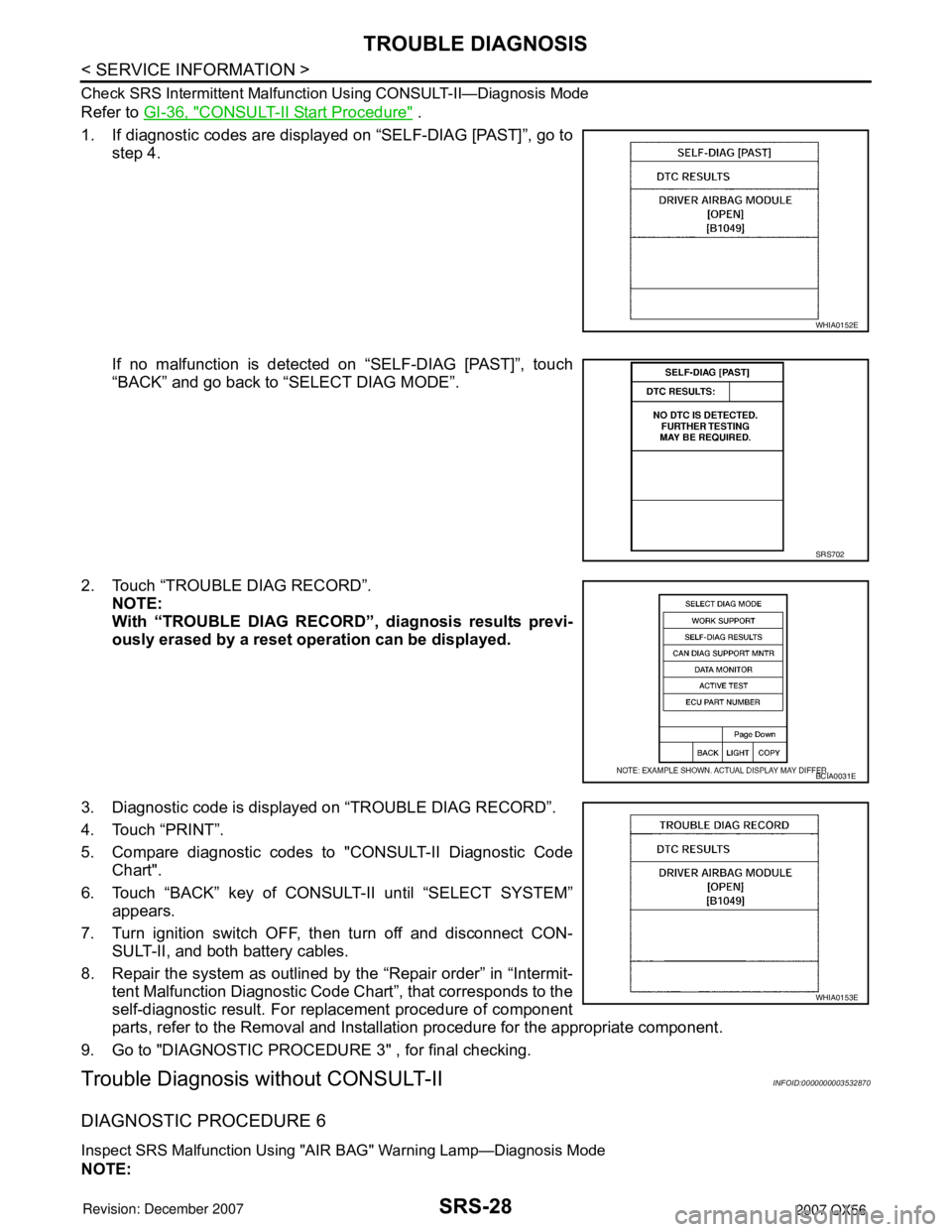
Check SRS Intermittent Malfunction Using CONSULT-II—Diagnosis Mode
Refer to GI-36, "CONSULT-II Start Procedure" .
1. If diagnostic codes are displayed on “SELF-DIAG [PAST]”, go to
step 4.
If no malfunction is detected on “SELF-DIAG [PAST]”, touch
“BACK” and go back to “SELECT DIAG MODE”.
2. Touch “TROUBLE DIAG RECORD”.
NOTE:
With “TROUBLE DIAG RECORD”, diagnosis results previ-
ously erased by a reset operation can be displayed.
3. Diagnostic code is displayed on “TROUBLE DIAG RECORD”.
4. Touch “PRINT”.
5. Compare diagnostic codes to "CONSULT-II Diagnostic Code
Chart".
6. Touch “BACK” key of CONSULT-II until “SELECT SYSTEM”
appears.
7. Turn ignition switch OFF, then turn off and disconnect CON-
SULT-II, and both battery cables.
8. Repair the system as outlined by the “Repair order” in “Intermit-
tent Malfunction Diagnostic Code Chart”, that corresponds to the
self-diagnostic result. For replacement procedure of component
parts, refer to the Removal and Installation procedure for the appropriate component.
9. Go to "DIAGNOSTIC PROCEDURE 3" , for final checking.
Trouble Diagnosis without CONSULT-IIINFOID:0000000003532870
DIAGNOSTIC PROCEDURE 6
Inspect SRS Malfunction Using "AIR BAG" Warning Lamp—Diagnosis Mode
NOTE:
WHIA0152E
SRS702
BCIA0031E
WHIA0153E