2007 INFINITI QX56 low oil pressure
[x] Cancel search: low oil pressurePage 2362 of 3061
SERVICE DATA AND SPECIFICATIONS (SDS)
LU-17
< SERVICE INFORMATION >
C
D
E
F
G
H
I
J
K
L
MA
LU
N
P O
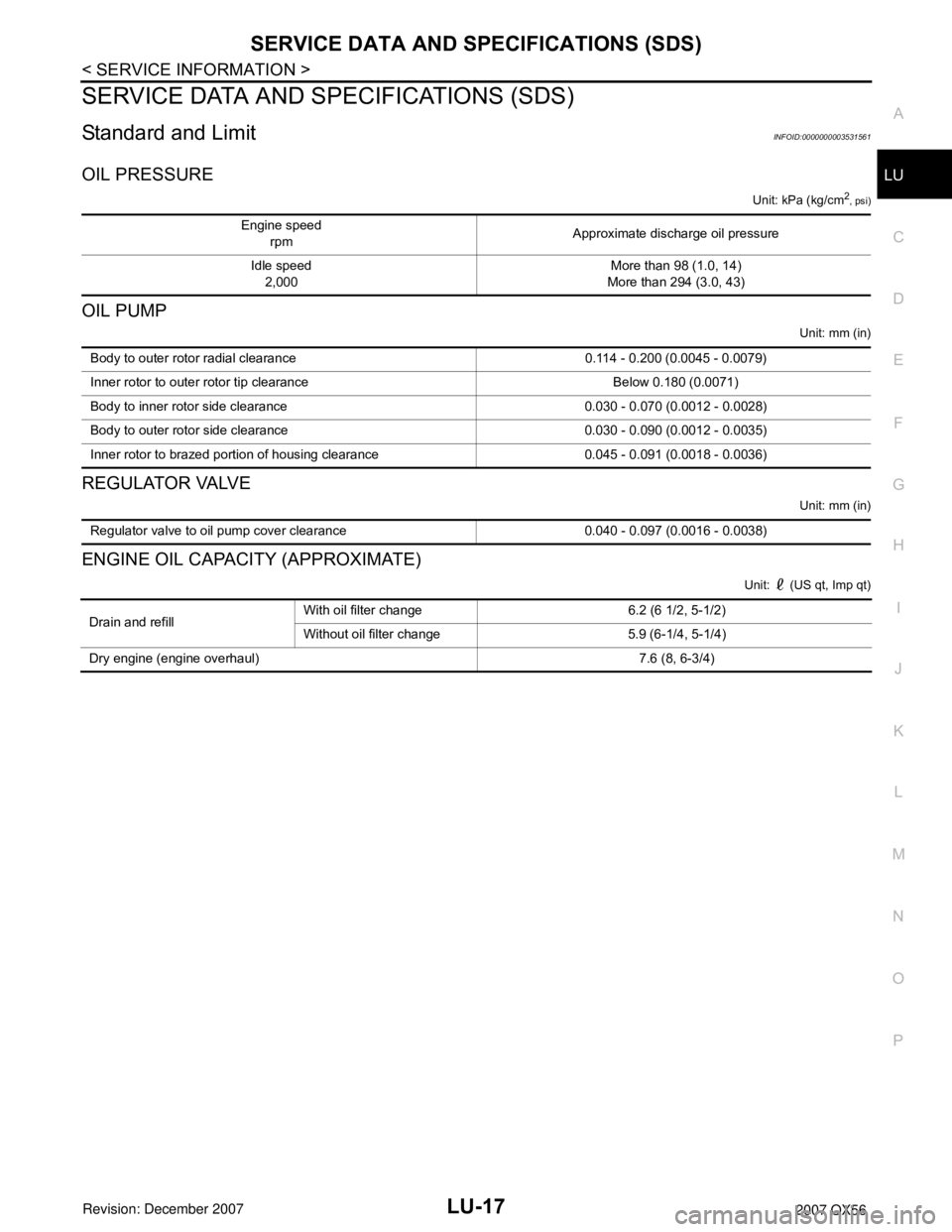
SERVICE DATA AND SPECIFICATIONS (SDS)
Standard and LimitINFOID:0000000003531561
OIL PRESSURE
Unit: kPa (kg/cm2
, psi)
OIL PUMP
Unit: mm (in)
REGULATOR VALVE
Unit: mm (in)
ENGINE OIL CAPACITY (APPROXIMATE)
Unit: (US qt, Imp qt)
Engine speed
rpm Approximate discharge oil pressure
Idle speed
2,000More than 98 (1.0, 14)
More than 294 (3.0, 43)
Body to outer rotor radial clearance 0.114 - 0.200 (0.0045 - 0.0079)
Inner rotor to outer rotor tip clearance Below 0.180 (0.0071)
Body to inner rotor side clearance 0.030 - 0.070 (0.0012 - 0.0028)
Body to outer rotor side clearance 0.030 - 0.090 (0.0012 - 0.0035)
Inner rotor to brazed portion of housing clearance 0.045 - 0.091 (0.0018 - 0.0036)
Regulator valve to oil pump cover clearance 0.040 - 0.097 (0.0016 - 0.0038)
Drain and refillWith oil filter change 6.2 (6 1/2, 5-1/2)
Without oil filter change 5.9 (6-1/4, 5-1/4)
Dry engine (engine overhaul) 7.6 (8, 6-3/4)
Page 2374 of 3061
MA-12
< SERVICE INFORMATION >
ENGINE MAINTENANCE
ENGINE MAINTENANCE
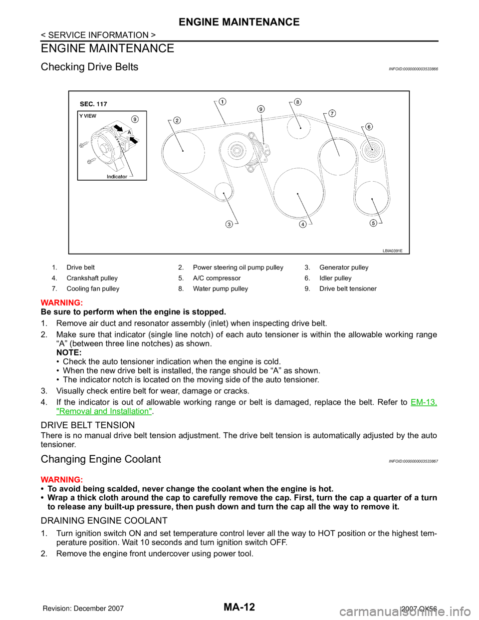
Checking Drive BeltsINFOID:0000000003533866
WARNING:
Be sure to perform when the engine is stopped.
1. Remove air duct and resonator assembly (inlet) when inspecting drive belt.
2. Make sure that indicator (single line notch) of each auto tensioner is within the allowable working range
“A” (between three line notches) as shown.
NOTE:
• Check the auto tensioner indication when the engine is cold.
• When the new drive belt is installed, the range should be “A” as shown.
• The indicator notch is located on the moving side of the auto tensioner.
3. Visually check entire belt for wear, damage or cracks.
4. If the indicator is out of allowable working range or belt is damaged, replace the belt. Refer to EM-13,
"Removal and Installation".
DRIVE BELT TENSION
There is no manual drive belt tension adjustment. The drive belt tension is automatically adjusted by the auto
tensioner.
Changing Engine CoolantINFOID:0000000003533867
WARNING:
• To avoid being scalded, never change the coolant when the engine is hot.
• Wrap a thick cloth around the cap to carefully remove the cap. First, turn the cap a quarter of a turn
to release any built-up pressure, then push down and turn the cap all the way to remove it.
DRAINING ENGINE COOLANT
1. Turn ignition switch ON and set temperature control lever all the way to HOT position or the highest tem-
perature position. Wait 10 seconds and turn ignition switch OFF.
2. Remove the engine front undercover using power tool.
1. Drive belt 2. Power steering oil pump pulley 3. Generator pulley
4. Crankshaft pulley 5. A/C compressor 6. Idler pulley
7. Cooling fan pulley 8. Water pump pulley 9. Drive belt tensioner
LBIA0391E
Page 2379 of 3061
ENGINE MAINTENANCE
MA-17
< SERVICE INFORMATION >
C
D
E
F
G
H
I
J
K
MA
B
MA
N
O
P
1. Remove the engine front undercover using power tool.
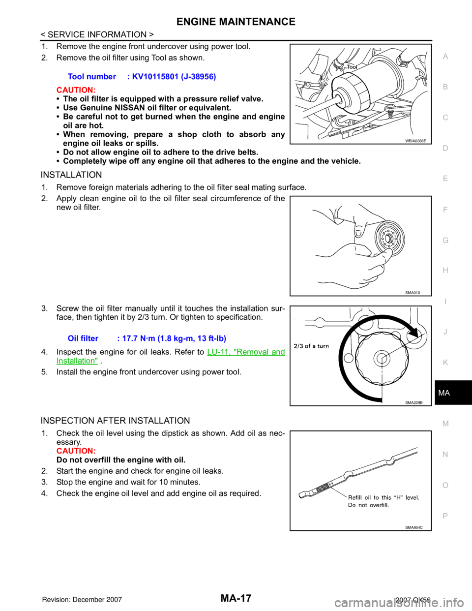
2. Remove the oil filter using Tool as shown.
CAUTION:
• The oil filter is equipped with a pressure relief valve.
• Use Genuine NISSAN oil filter or equivalent.
• Be careful not to get burned when the engine and engine
oil are hot.
• When removing, prepare a shop cloth to absorb any
engine oil leaks or spills.
• Do not allow engine oil to adhere to the drive belts.
• Completely wipe off any engine oil that adheres to the engine and the vehicle.
INSTALLATION
1. Remove foreign materials adhering to the oil filter seal mating surface.
2. Apply clean engine oil to the oil filter seal circumference of the
new oil filter.
3. Screw the oil filter manually until it touches the installation sur-
face, then tighten it by 2/3 turn. Or tighten to specification.
4. Inspect the engine for oil leaks. Refer to LU-11, "
Removal and
Installation" .
5. Install the engine front undercover using power tool.
INSPECTION AFTER INSTALLATION
1. Check the oil level using the dipstick as shown. Add oil as nec-
essary.
CAUTION:
Do not overfill the engine with oil.
2. Start the engine and check for engine oil leaks.
3. Stop the engine and wait for 10 minutes.
4. Check the engine oil level and add engine oil as required.Tool number : KV10115801 (J-38956)
WBIA0388E
SMA010
Oil filter : 17.7 N·m (1.8 kg-m, 13 ft-lb)
SMA229B
SMA954C
Page 2421 of 3061
IPDM E/R (INTELLIGENT POWER DISTRIBUTION MODULE ENGINE ROOM)
PG-19
< SERVICE INFORMATION >
C
D
E
F
G
H
I
J
L
MA
B
PG
N
O
P
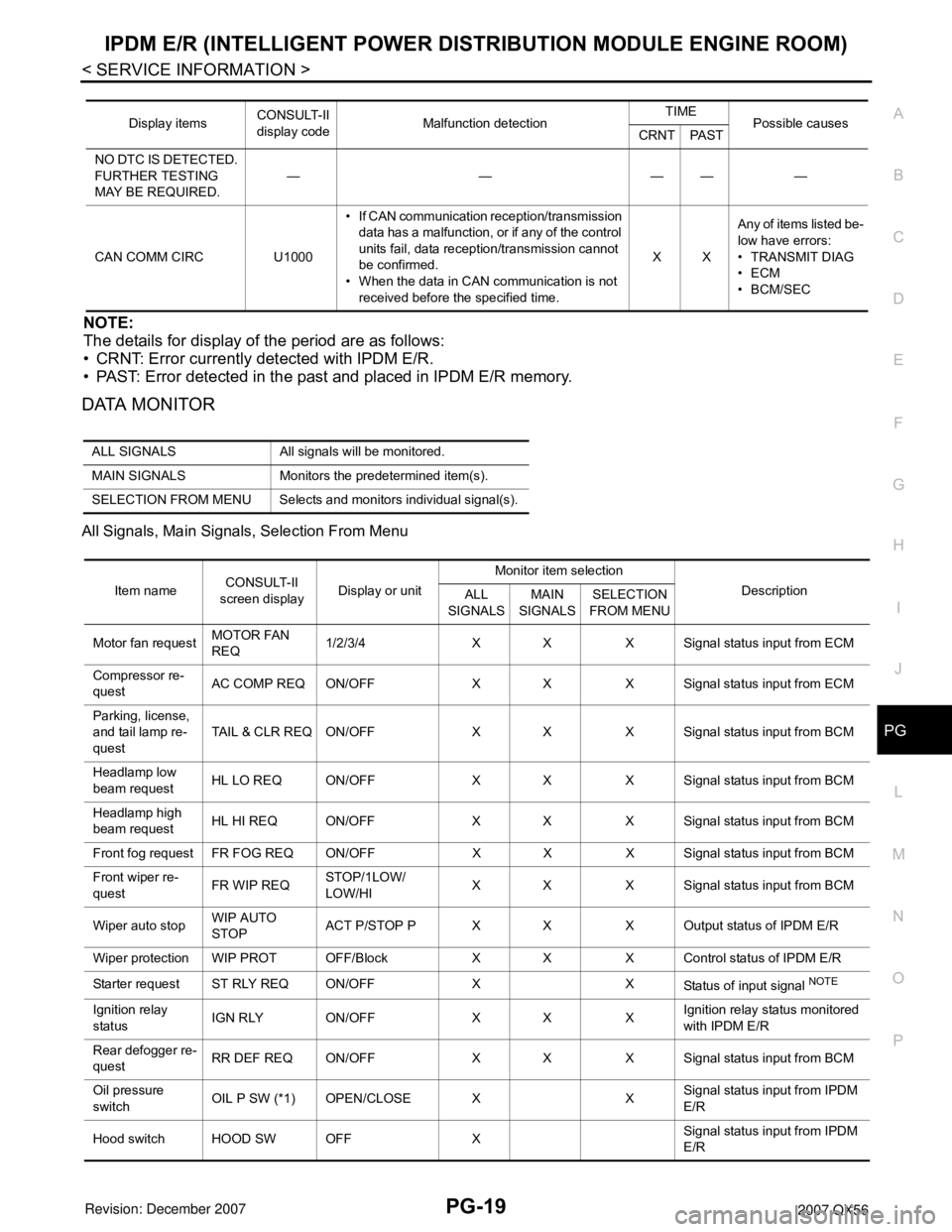
NOTE:
The details for display of the period are as follows:
• CRNT: Error currently detected with IPDM E/R.
• PAST: Error detected in the past and placed in IPDM E/R memory.
DATA MONITOR
All Signals, Main Signals, Selection From Menu
Display itemsCONSULT-II
display codeMalfunction detectionTIME
Possible causes
CRNT PAST
NO DTC IS DETECTED.
FURTHER TESTING
MAY BE REQUIRED.—————
CAN COMM CIRC U1000• If CAN communication reception/transmission
data has a malfunction, or if any of the control
units fail, data reception/transmission cannot
be confirmed.
• When the data in CAN communication is not
received before the specified time.XXAny of items listed be-
low have errors:
• TRANSMIT DIAG
•ECM
•BCM/SEC
ALL SIGNALS All signals will be monitored.
MAIN SIGNALS Monitors the predetermined item(s).
SELECTION FROM MENU Selects and monitors individual signal(s).
Item nameCONSULT-II
screen displayDisplay or unitMonitor item selection
Description
ALL
SIGNALSMAIN
SIGNALSSELECTION
FROM MENU
Motor fan requestMOTOR FAN
REQ1/2/3/4 X X X Signal status input from ECM
Compressor re-
questAC COMP REQ ON/OFF X X X Signal status input from ECM
Parking, license,
and tail lamp re-
questTAIL & CLR REQ ON/OFF X X X Signal status input from BCM
Headlamp low
beam requestHL LO REQ ON/OFF X X X Signal status input from BCM
Headlamp high
beam requestHL HI REQ ON/OFF X X X Signal status input from BCM
Front fog request FR FOG REQ ON/OFF X X X Signal status input from BCM
Front wiper re-
questFR WIP REQSTOP/1LOW/
LOW/HIX X X Signal status input from BCM
Wiper auto stopWIP AUTO
STOPACT P/STOP P X X X Output status of IPDM E/R
Wiper protection WIP PROT OFF/Block X X X Control status of IPDM E/R
Starter request ST RLY REQ ON/OFF X X
Status of input signal
NOTE
Ignition relay
statusIGN RLY ON/OFF X X XIgnition relay status monitored
with IPDM E/R
Rear defogger re-
questRR DEF REQ ON/OFF X X X Signal status input from BCM
Oil pressure
switchOIL P SW (*1) OPEN/CLOSE X XSignal status input from IPDM
E/R
Hood switch HOOD SW OFF XSignal status input from IPDM
E/R
Page 2507 of 3061
PS-16
< SERVICE INFORMATION >
POWER STEERING GEAR AND LINKAGE
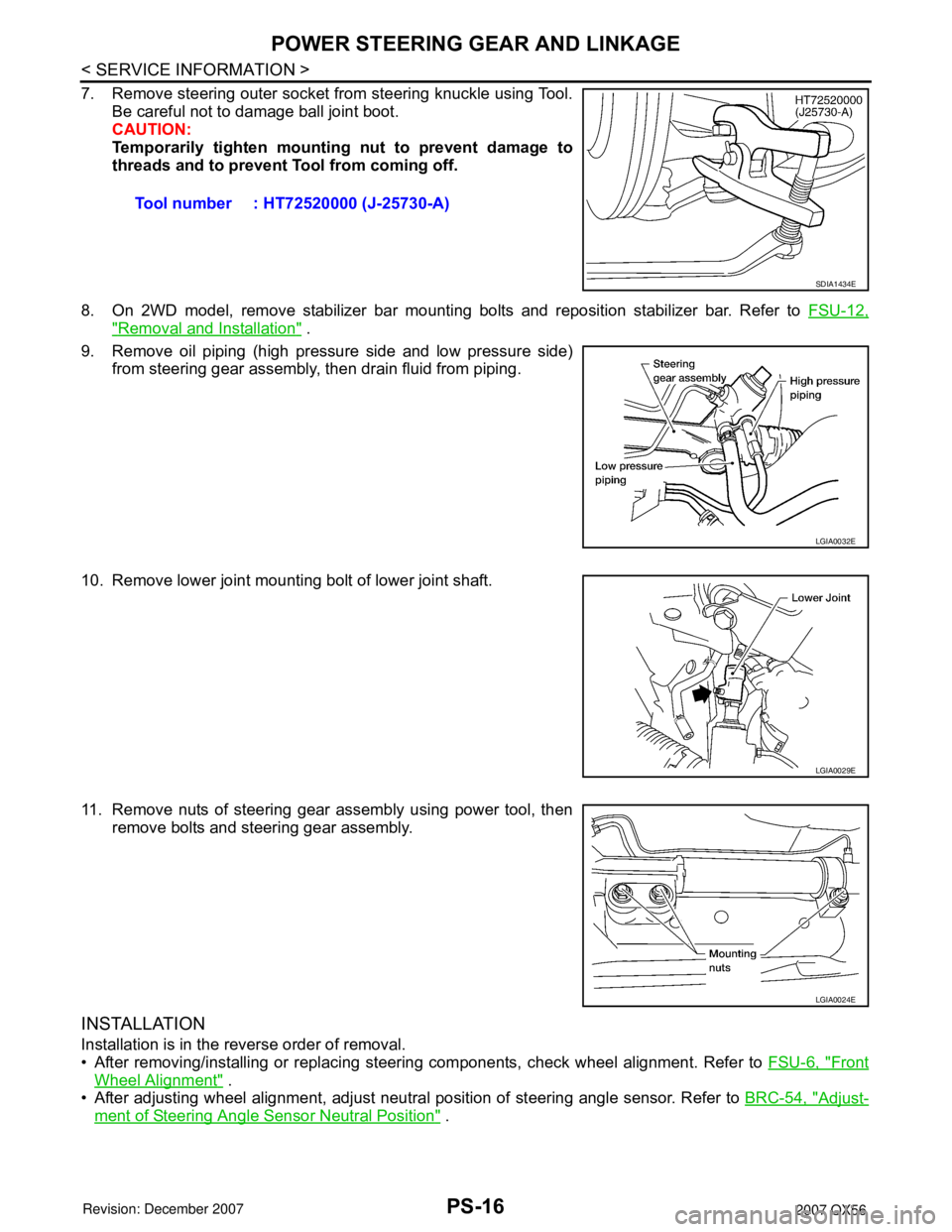
7. Remove steering outer socket from steering knuckle using Tool.
Be careful not to damage ball joint boot.
CAUTION:
Temporarily tighten mounting nut to prevent damage to
threads and to prevent Tool from coming off.
8. On 2WD model, remove stabilizer bar mounting bolts and reposition stabilizer bar. Refer to FSU-12,
"Removal and Installation" .
9. Remove oil piping (high pressure side and low pressure side)
from steering gear assembly, then drain fluid from piping.
10. Remove lower joint mounting bolt of lower joint shaft.
11. Remove nuts of steering gear assembly using power tool, then
remove bolts and steering gear assembly.
INSTALLATION
Installation is in the reverse order of removal.
• After removing/installing or replacing steering components, check wheel alignment. Refer to FSU-6, "
Front
Wheel Alignment" .
• After adjusting wheel alignment, adjust neutral position of steering angle sensor. Refer to BRC-54, "
Adjust-
ment of Steering Angle Sensor Neutral Position" . Tool number : HT72520000 (J-25730-A)
SDIA1434E
LGIA0032E
LGIA0029E
LGIA0024E
Page 2512 of 3061
POWER STEERING OIL PUMP
PS-21
< SERVICE INFORMATION >
C
D
E
F
H
I
J
K
L
MA
B
PS
N
O
P
POWER STEERING OIL PUMP
On-Vehicle Inspection and ServiceINFOID:0000000003532831
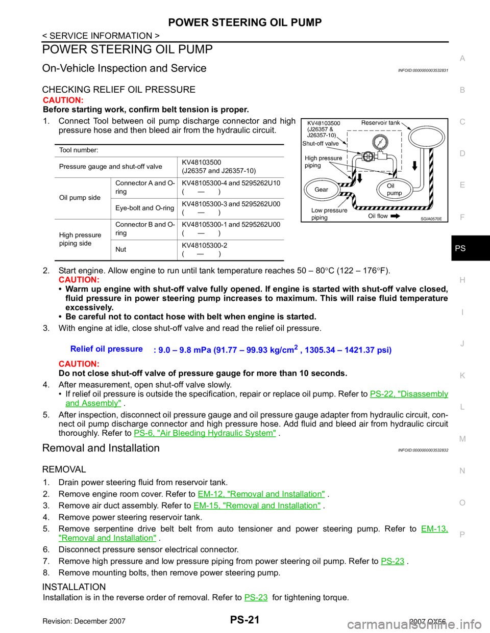
CHECKING RELIEF OIL PRESSURE
CAUTION:
Before starting work, confirm belt tension is proper.
1. Connect Tool between oil pump discharge connector and high
pressure hose and then bleed air from the hydraulic circuit.
2. Start engine. Allow engine to run until tank temperature reaches 50 – 80°C (122 – 176°F).
CAUTION:
• Warm up engine with shut-off valve fully opened. If engine is started with shut-off valve closed,
fluid pressure in power steering pump increases to maximum. This will raise fluid temperature
excessively.
• Be careful not to contact hose with belt when engine is started.
3. With engine at idle, close shut-off valve and read the relief oil pressure.
CAUTION:
Do not close shut-off valve of pressure gauge for more than 10 seconds.
4. After measurement, open shut-off valve slowly.
• If relief oil pressure is outside the specification, repair or replace oil pump. Refer to PS-22, "
Disassembly
and Assembly" .
5. After inspection, disconnect oil pressure gauge and oil pressure gauge adapter from hydraulic circuit, con-
nect oil pump discharge connector and high pressure hose. Add fluid and bleed air from hydraulic circuit
thoroughly. Refer to PS-6, "
Air Bleeding Hydraulic System" .
Removal and InstallationINFOID:0000000003532832
REMOVAL
1. Drain power steering fluid from reservoir tank.
2. Remove engine room cover. Refer to EM-12, "
Removal and Installation" .
3. Remove air duct assembly. Refer to EM-15, "
Removal and Installation" .
4. Remove power steering reservoir tank.
5. Remove serpentine drive belt belt from auto tensioner and power steering pump. Refer to EM-13,
"Removal and Installation" .
6. Disconnect pressure sensor electrical connector.
7. Remove high pressure and low pressure piping from power steering oil pump. Refer to PS-23
.
8. Remove mounting bolts, then remove power steering pump.
INSTALLATION
Installation is in the reverse order of removal. Refer to PS-23 for tightening torque.
Tool number:
Pressure gauge and shut-off valveKV48103500
(J26357 and J26357-10)
Oil pump sideConnector A and O-
ringKV48105300-4 and 5295262U10
(—)
Eye-bolt and O-ringKV48105300-3 and 5295262U00
(—)
High pressure
piping sideConnector B and O-
ringKV48105300-1 and 5295262U00
(—)
NutKV48105300-2
( — )
SGIA0570E
Relief oil pressure
: 9.0 – 9.8 mPa (91.77 – 99.93 kg/cm2 , 1305.34 – 1421.37 psi)
Page 2513 of 3061
PS-22
< SERVICE INFORMATION >
POWER STEERING OIL PUMP
• After installation, bleed air. Refer to PS-6, "Air Bleeding Hydraulic System" .
NOTE:
Belt tension is automatic and requires no adjustment.
Disassembly and AssemblyINFOID:0000000003532833
INSPECTION BEFORE DISASSEMBLY
Disassemble the power steering oil pump only if the following items are found.
• Deformed or damaged pulley, bracket, connector or suction pipe.
• Oil leakage from the suction pipe or connector.
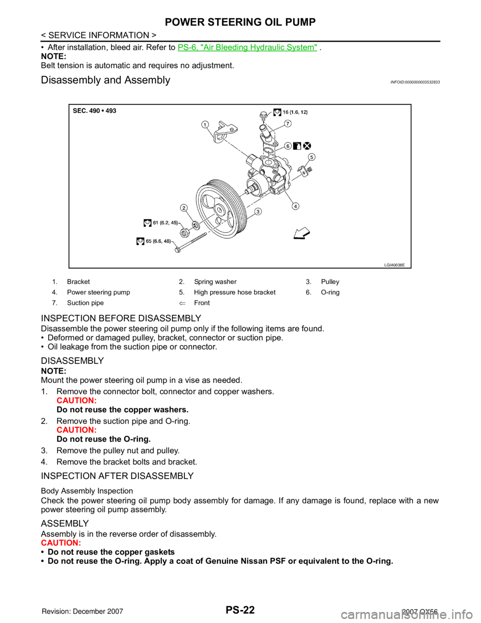
DISASSEMBLY
NOTE:
Mount the power steering oil pump in a vise as needed.
1. Remove the connector bolt, connector and copper washers.
CAUTION:
Do not reuse the copper washers.
2. Remove the suction pipe and O-ring.
CAUTION:
Do not reuse the O-ring.
3. Remove the pulley nut and pulley.
4. Remove the bracket bolts and bracket.
INSPECTION AFTER DISASSEMBLY
Body Assembly Inspection
Check the power steering oil pump body assembly for damage. If any damage is found, replace with a new
power steering oil pump assembly.
ASSEMBLY
Assembly is in the reverse order of disassembly.
CAUTION:
• Do not reuse the copper gaskets
• Do not reuse the O-ring. Apply a coat of Genuine Nissan PSF or equivalent to the O-ring.
1. Bracket 2. Spring washer 3. Pulley
4. Power steering pump 5. High pressure hose bracket 6. O-ring
7. Suction pipe⇐Front
LGIA0038E
Page 2514 of 3061
HYDRAULIC LINE
PS-23
< SERVICE INFORMATION >
C
D
E
F
H
I
J
K
L
MA
B
PS
N
O
P
HYDRAULIC LINE
Removal and InstallationINFOID:0000000003532834
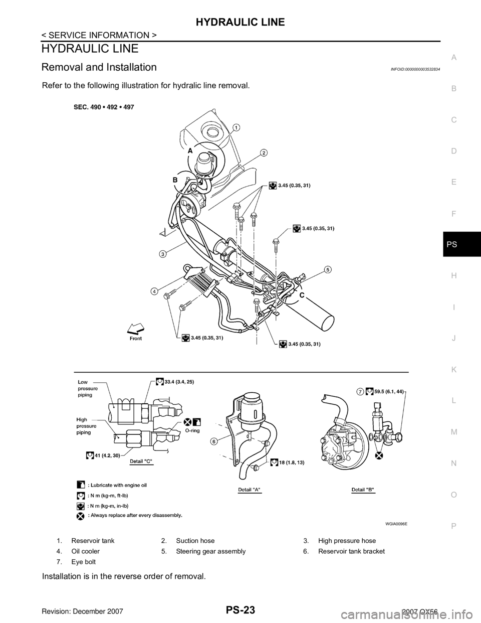
Refer to the following illustration for hydralic line removal.
Installation is in the reverse order of removal.
1. Reservoir tank 2. Suction hose 3. High pressure hose
4. Oil cooler 5. Steering gear assembly 6. Reservoir tank bracket
7. Eye bolt
WGIA0096E