2007 INFINITI QX56 low oil pressure
[x] Cancel search: low oil pressurePage 1173 of 3061

EC-90
< SERVICE INFORMATION >
TROUBLE DIAGNOSIS
Symptom Matrix Chart
INFOID:0000000003531620
SYSTEM — BASIC ENGINE CONTROL SYSTEM
SYMPTOM
Refer-
ence page
HARD/NO START/RESTART (EXCP. HA)
ENGINE STALL
HESITATION/SURGING/FLAT SPOT
SPARK KNOCK/DETONATION
LACK OF POWER/POOR ACCELERATION
HIGH IDLE/LOW IDLE
ROUGH IDLE/HUNTING
IDLING VIBRATION
SLOW/NO RETURN TO IDLE
OVERHEATS/WATER TEMPERATURE HIGH
EXCESSIVE FUEL CONSUMPTION
EXCESSIVE OIL CONSUMPTION
BATTERY DEAD (UNDER CHARGE)
Warranty symptom code AA AB AC AD AE AF AG AH AJ AK AL AM HA
Fuel Fuel pump circuit 11232 22 3 2EC-613
Fuel pressure regulator system 334444444 4EC-80
Injector circuit 11232 22 2EC-608
Evaporative emission system 334444444 4EC-33
Air Positive crankcase ventilation sys-
tem
334444444 41EC-45
Incorrect idle speed adjustment 1 1 1 1 1EC-71
Electric throttle control actuator 112332222 2 2EC-543
,
EC-548
,
EC-554
,
EC-559
IgnitionIncorrect ignition timing adjustment 33111 11 1EC-71
Ignition circuit 11222 22 2EC-626
Main power supply and ground circuit 22333 33 23EC-139
Mass air flow sensor circuit
1
122
222 2EC-186,
EC-194
Engine coolant temperature sensor circuit
333EC-205,
EC-217
Air fuel ratio (A/F) sensor 1 circuitEC-225
,
EC-234
,
EC-242
,
EC-250
,
EC-588
Throttle position sensor circuit
22EC-210
,
EC-318
,
EC-477
,
EC-479
,
EC-574
Accelerator pedal position sensor circuit 3 2 1EC-440
,
EC-561
,
EC-567
,
EC-581
Knock sensor circuit 2 3EC-332
Crankshaft position sensor (POS) circuit 2 2EC-336
Page 1174 of 3061
TROUBLE DIAGNOSIS
EC-91
< SERVICE INFORMATION >
C
D
E
F
G
H
I
J
K
L
MA
EC
N
P O
1 - 6: The numbers refer to the order of inspection.
(continued on next page)
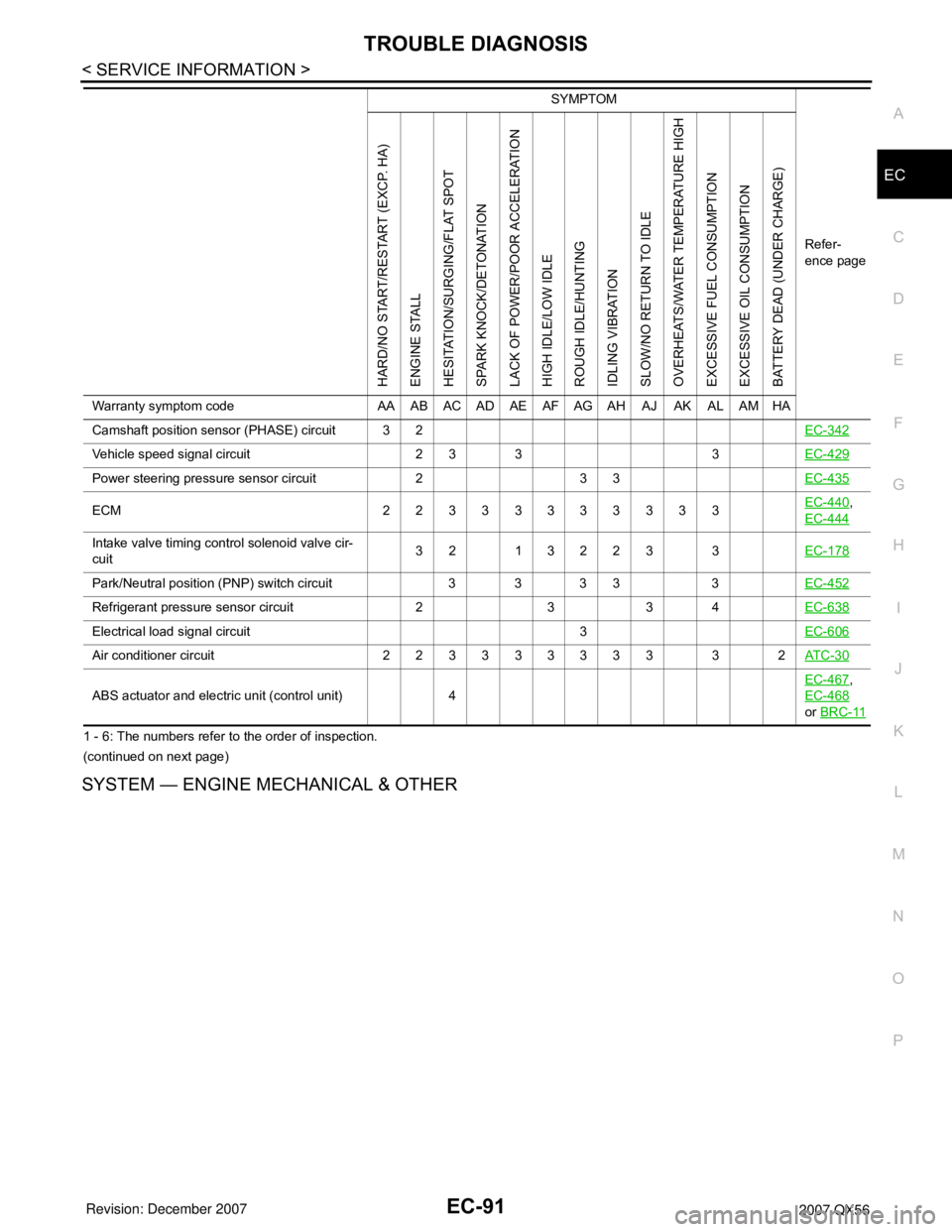
SYSTEM — ENGINE MECHANICAL & OTHER
Camshaft position sensor (PHASE) circuit 3 2EC-342
Vehicle speed signal circuit 2 3 3 3EC-429
Power steering pressure sensor circuit 2 3 3EC-435
ECM 22333333333EC-440,
EC-444
Intake valve timing control solenoid valve cir-
cuit32 13223 3EC-178
Park/Neutral position (PNP) switch circuit 3 3 3 3 3EC-452
Refrigerant pressure sensor circuit 2 3 3 4EC-638
Electrical load signal circuit 3EC-606
Air conditioner circuit 223333333 3 2AT C - 3 0
ABS actuator and electric unit (control unit) 4EC-467
,
EC-468
or BRC-11
SYMPTOM
Refer-
ence page
HARD/NO START/RESTART (EXCP. HA)
ENGINE STALL
HESITATION/SURGING/FLAT SPOT
SPARK KNOCK/DETONATION
LACK OF POWER/POOR ACCELERATION
HIGH IDLE/LOW IDLE
ROUGH IDLE/HUNTING
IDLING VIBRATION
SLOW/NO RETURN TO IDLE
OVERHEATS/WATER TEMPERATURE HIGH
EXCESSIVE FUEL CONSUMPTION
EXCESSIVE OIL CONSUMPTION
BATTERY DEAD (UNDER CHARGE)
Warranty symptom code AA AB AC AD AE AF AG AH AJ AK AL AM HA
Page 1177 of 3061
EC-94
< SERVICE INFORMATION >
TROUBLE DIAGNOSIS
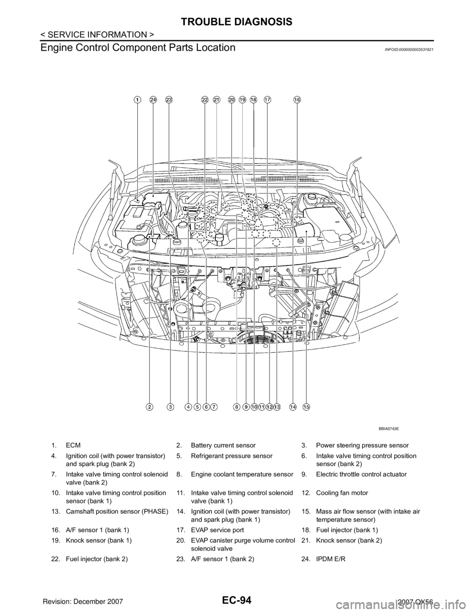
Engine Control Component Parts Location
INFOID:0000000003531621
1. ECM 2. Battery current sensor 3. Power steering pressure sensor
4. Ignition coil (with power transistor)
and spark plug (bank 2)5. Refrigerant pressure sensor 6. Intake valve timing control position
sensor (bank 2)
7. Intake valve timing control solenoid
valve (bank 2)8. Engine coolant temperature sensor 9. Electric throttle control actuator
10. Intake valve timing control position
sensor (bank 1)11. Intake valve timing control solenoid
valve (bank 1)12. Cooling fan motor
13. Camshaft position sensor (PHASE) 14. Ignition coil (with power transistor)
and spark plug (bank 1)15. Mass air flow sensor (with intake air
temperature sensor)
16. A/F sensor 1 (bank 1) 17. EVAP service port 18. Fuel injector (bank 1)
19. Knock sensor (bank 1) 20. EVAP canister purge volume control
solenoid valve21. Knock sensor (bank 2)
22. Fuel injector (bank 2) 23. A/F sensor 1 (bank 2) 24. IPDM E/R
BBIA0743E
Page 1216 of 3061
TROUBLE DIAGNOSIS - SPECIFICATION VALUE
EC-133
< SERVICE INFORMATION >
C
D
E
F
G
H
I
J
K
L
MA
EC
N
P O
6.CHECK FUEL PRESSURE
Check fuel pressure. (Refer to EC-80, "
Fuel Pressure Check" .)
OK or NG
OK >> GO TO 9.
NG (Fuel pressure is too high)>>Replace fuel pressure regulator, refer to EC-80, "
Fuel Pressure Check" .
GO TO 8.
NG (Fuel pressure is too low)>>GO TO 7.
7.DETECT MALFUNCTIONING PART
1. Check the following.
- Clogged and bent fuel hose and fuel tube
- Clogged fuel filter
- Fuel pump and its circuit (Refer to EC-613
.)
2. If NG, repair or replace the malfunctioning part. (Refer to EC-80, "
Fuel Pressure Check" .)
If OK, replace fuel pressure regulator.
>> GO TO 8.
8.CHECK “A/F ALPHA-B1”, “A/F ALPHA-B2”
1. Start engine.
2. Select “A/F ALPHA-B1”, “A/F ALPHA-B2” in “DATA MONITOR (SPEC)” mode, and make sure that the
each indication is within the SP value.
OK or NG
OK >>INSPECTION END
NG >> GO TO 9.
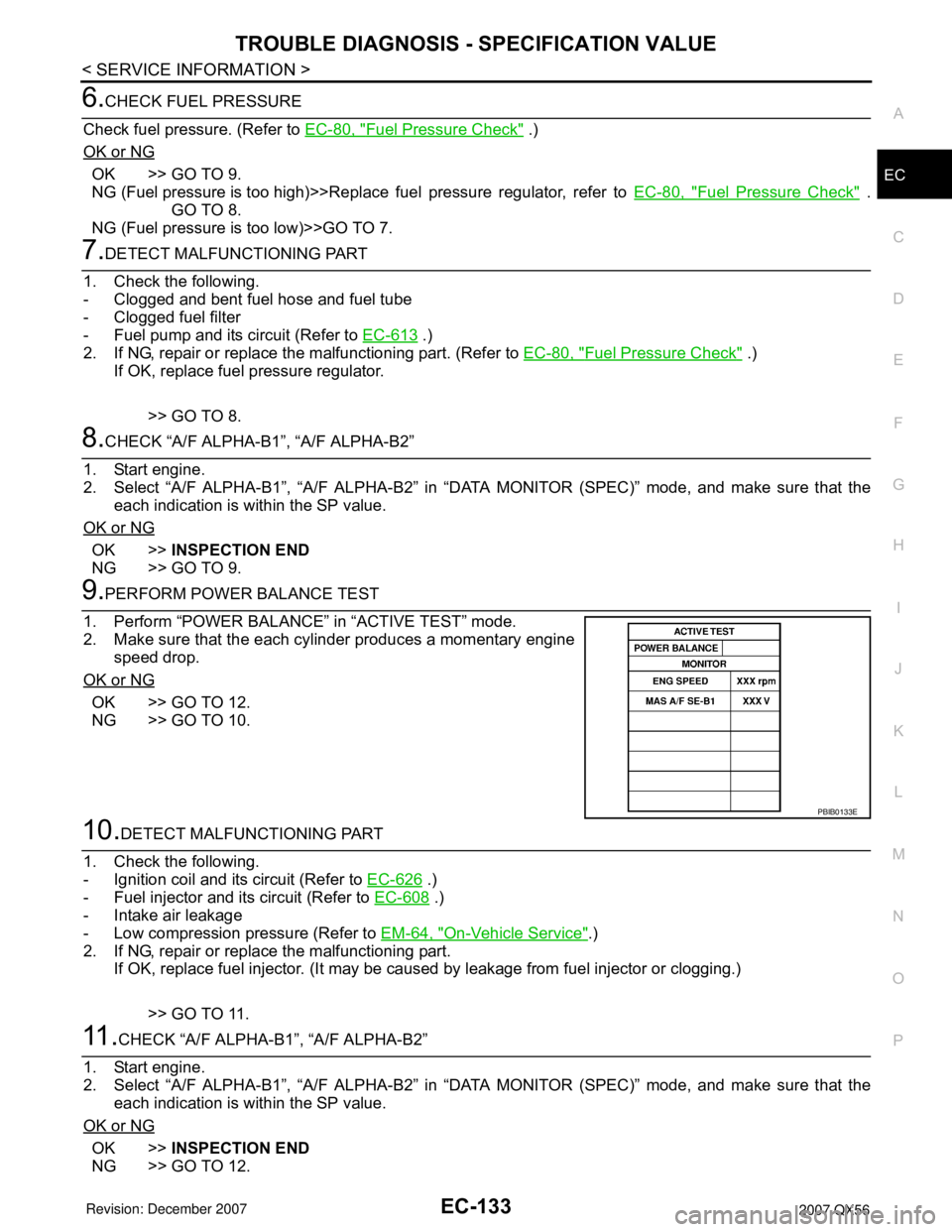
9.PERFORM POWER BALANCE TEST
1. Perform “POWER BALANCE” in “ACTIVE TEST” mode.
2. Make sure that the each cylinder produces a momentary engine
speed drop.
OK or NG
OK >> GO TO 12.
NG >> GO TO 10.
10.DETECT MALFUNCTIONING PART
1. Check the following.
- Ignition coil and its circuit (Refer to EC-626
.)
- Fuel injector and its circuit (Refer to EC-608
.)
- Intake air leakage
- Low compression pressure (Refer to EM-64, "
On-Vehicle Service".)
2. If NG, repair or replace the malfunctioning part.
If OK, replace fuel injector. (It may be caused by leakage from fuel injector or clogging.)
>> GO TO 11.
11 .CHECK “A/F ALPHA-B1”, “A/F ALPHA-B2”
1. Start engine.
2. Select “A/F ALPHA-B1”, “A/F ALPHA-B2” in “DATA MONITOR (SPEC)” mode, and make sure that the
each indication is within the SP value.
OK or NG
OK >>INSPECTION END
NG >> GO TO 12.
PBIB0133E
Page 1232 of 3061
DTC P0011, P0021 IVT CONTROL
EC-149
< SERVICE INFORMATION >
C
D
E
F
G
H
I
J
K
L
MA
EC
N
P O
DTC P0011, P0021 IVT CONTROL
DescriptionINFOID:0000000003531648
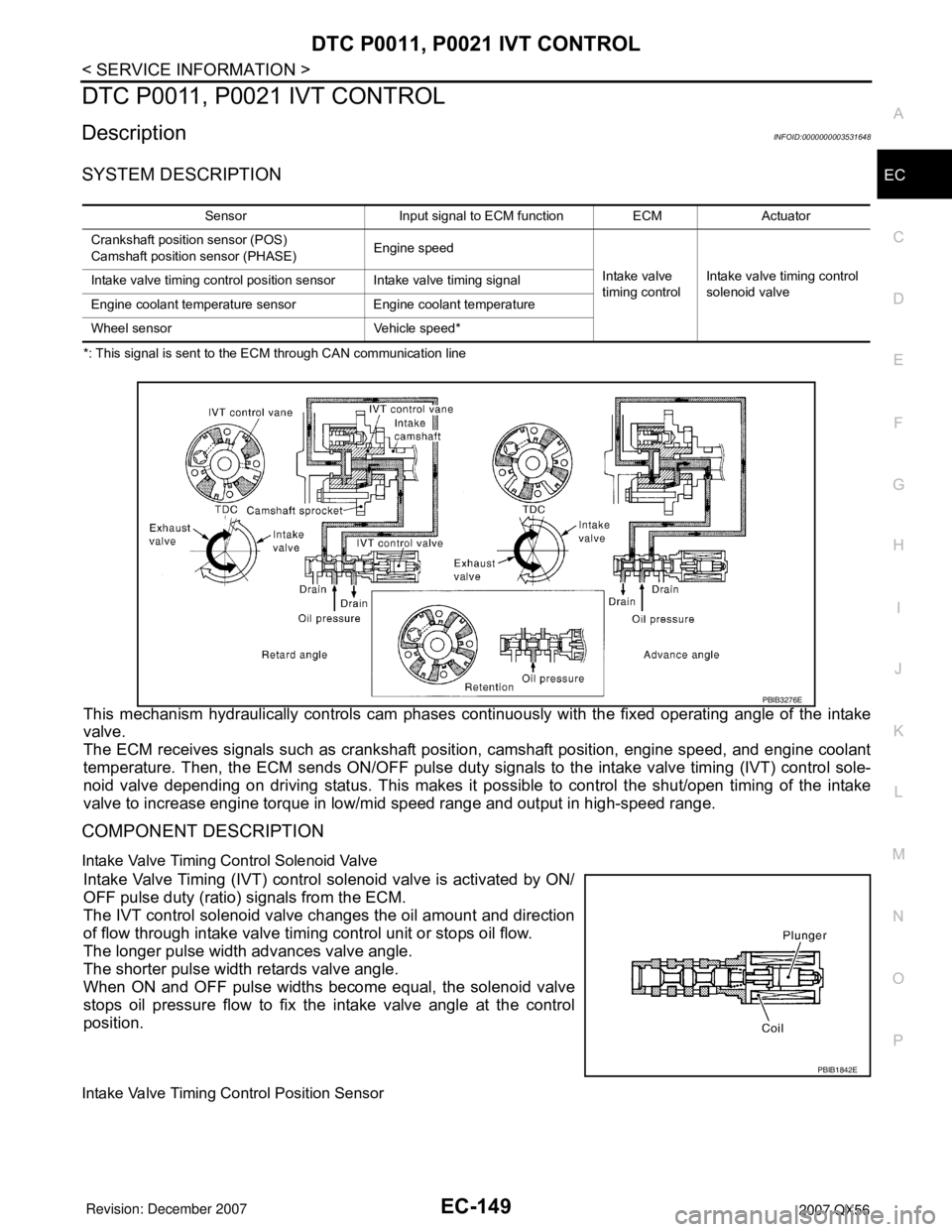
SYSTEM DESCRIPTION
*: This signal is sent to the ECM through CAN communication line
This mechanism hydraulically controls cam phases continuously with the fixed operating angle of the intake
valve.
The ECM receives signals such as crankshaft position, camshaft position, engine speed, and engine coolant
temperature. Then, the ECM sends ON/OFF pulse duty signals to the intake valve timing (IVT) control sole-
noid valve depending on driving status. This makes it possible to control the shut/open timing of the intake
valve to increase engine torque in low/mid speed range and output in high-speed range.
COMPONENT DESCRIPTION
Intake Valve Timing Control Solenoid Valve
Intake Valve Timing (IVT) control solenoid valve is activated by ON/
OFF pulse duty (ratio) signals from the ECM.
The IVT control solenoid valve changes the oil amount and direction
of flow through intake valve timing control unit or stops oil flow.
The longer pulse width advances valve angle.
The shorter pulse width retards valve angle.
When ON and OFF pulse widths become equal, the solenoid valve
stops oil pressure flow to fix the intake valve angle at the control
position.
Intake Valve Timing Control Position Sensor
Sensor Input signal to ECM function ECM Actuator
Crankshaft position sensor (POS)
Camshaft position sensor (PHASE)Engine speed
Intake valve
timing controlIntake valve timing control
solenoid valve Intake valve timing control position sensor Intake valve timing signal
Engine coolant temperature sensor Engine coolant temperature
Wheel sensor Vehicle speed*
PBIB3276E
PBIB1842E
Page 1261 of 3061
EC-178
< SERVICE INFORMATION >
DTC P0075, P0081 IVT CONTROL SOLENOID VALVE
DTC P0075, P0081 IVT CONTROL SOLENOID VALVE
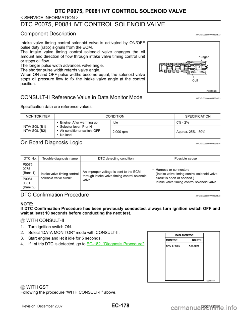
Component DescriptionINFOID:0000000003531672
Intake valve timing control solenoid valve is activated by ON/OFF
pulse duty (ratio) signals from the ECM.
The intake valve timing control solenoid valve changes the oil
amount and direction of flow through intake valve timing control unit
or stops oil flow.
The longer pulse width advances valve angle.
The shorter pulse width retards valve angle.
When ON and OFF pulse widths become equal, the solenoid valve
stops oil pressure flow to fix the intake valve angle at the control
position.
CONSULT-II Reference Value in Data Monitor ModeINFOID:0000000003531673
Specification data are reference values.
On Board Diagnosis LogicINFOID:0000000003531674
DTC Confirmation ProcedureINFOID:0000000003531675
NOTE:
If DTC Confirmation Procedure has been previously conducted, always turn ignition switch OFF and
wait at least 10 seconds before conducting the next test.
WITH CONSULT-II
1. Turn ignition switch ON.
2. Select “DATA MONITOR” mode with CONSULT-II.
3. Start engine and let it idle for 5 seconds.
4. If 1st trip DTC is detected, go to EC-182, "
Diagnosis Procedure".
WITH GST
Following the procedure “WITH CONSULT-II” above.
PBIB1842E
MONITOR ITEM CONDITION SPECIFICATION
INT/V SOL (B1)
INT/V SOL (B2)• Engine: After warming up
• Selector lever: P or N
• Air conditioner switch: OFF
•No loadIdle 0% - 2%
2,000 rpm Approx. 25% - 50%
DTC No. Trouble diagnosis name DTC detecting condition Possible cause
P0075
0075
(Bank 1)
Intake valve timing control
solenoid valve circuitAn improper voltage is sent to the ECM
through intake valve timing control solenoid
valve.• Harness or connectors
(Intake valve timing control solenoid valve
circuit is open or shorted.)
• Intake valve timing control solenoid valve P0081
0081
(Bank 2)
SEF058Y
Page 1391 of 3061
EC-308
< SERVICE INFORMATION >
DTC P0172, P0175 FUEL INJECTION SYSTEM FUNCTION
• Fuel pressure regulator (Refer to EC-80, "Fuel Pressure Check".)
>> Repair or replace.
6.CHECK MASS AIR FLOW SENSOR
With CONSULT-II
1. Install all removed parts.
2. Check “MASS AIR FLOW” in “DATA MONITOR” mode with CONSULT-II.
With GST
1. Install all removed parts.
2. Check mass air flow sensor signal in Service $01 with GST.
OK or NG
OK >> GO TO 7.
NG >> Check connectors for rusted terminals or loose connections in the mass air flow sensor circuit or
grounds. Refer to EC-186
.
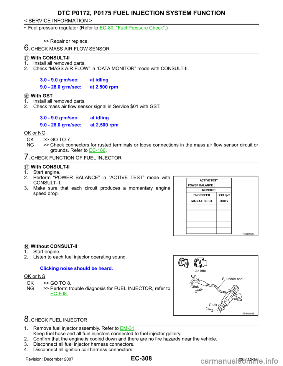
7.CHECK FUNCTION OF FUEL INJECTOR
With CONSULT-II
1. Start engine.
2. Perform “POWER BALANCE” in “ACTIVE TEST” mode with
CONSULT-II.
3. Make sure that each circuit produces a momentary engine
speed drop.
Without CONSULT-II
1. Start engine.
2. Listen to each fuel injector operating sound.
OK or NG
OK >> GO TO 8.
NG >> Perform trouble diagnosis for FUEL INJECTOR, refer to
EC-608
.
8.CHECK FUEL INJECTOR
1. Remove fuel injector assembly. Refer to EM-31
.
Keep fuel hose and all fuel injectors connected to fuel injector gallery.
2. Confirm that the engine is cooled down and there are no fire hazards near the vehicle.
3. Disconnect all fuel injector harness connectors.
4. Disconnect all ignition coil harness connectors.3.0 - 9.0 g·m/sec: at idling
9.0 - 28.0 g·m/sec: at 2,500 rpm
3.0 - 9.0 g·m/sec: at idling
9.0 - 28.0 g·m/sec: at 2,500 rpm
PBIB0133E
Clicking noise should be heard.
PBIB1986E
Page 1410 of 3061
DTC P0300 - P0308 MULTIPLE CYLINDER MISFIRE, NO. 1 - 8 CYLINDER MIS-
FIRE
EC-327
< SERVICE INFORMATION >
C
D
E
F
G
H
I
J
K
L
MA
EC
N
P O
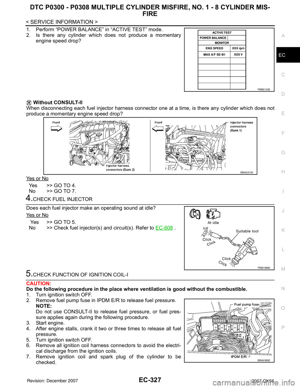
1. Perform “POWER BALANCE” in “ACTIVE TEST” mode.
2. Is there any cylinder which does not produce a momentary
engine speed drop?
Without CONSULT-II
When disconnecting each fuel injector harness connector one at a time, is there any cylinder which does not
produce a momentary engine speed drop?
Ye s o r N o
Yes >> GO TO 4.
No >> GO TO 7.
4.CHECK FUEL INJECTOR
Does each fuel injector make an operating sound at idle?
Ye s o r N o
Yes >> GO TO 5.
No >> Check fuel injector(s) and circuit(s). Refer to EC-608
.
5.CHECK FUNCTION OF IGNITION COIL-I
CAUTION:
Do the following procedure in the place where ventilation is good without the combustible.
1. Turn ignition switch OFF.
2. Remove fuel pump fuse in IPDM E/R to release fuel pressure.
NOTE:
Do not use CONSULT-II to release fuel pressure, or fuel pres-
sure applies again during the following procedure.
3. Start engine.
4. After engine stalls, crank it two or three times to release all fuel
pressure.
5. Turn ignition switch OFF.
6. Remove all ignition coil harness connectors to avoid the electri-
cal discharge from the ignition coils.
7. Remove ignition coil and spark plug of the cylinder to be
checked.
PBIB0133E
BBIA0374E
PBIB1986E
BBIA0380E