2007 INFINITI QX56 door lock
[x] Cancel search: door lockPage 824 of 3061

REAR DOOR LOCK
BL-113
< SERVICE INFORMATION >
C
D
E
F
G
H
J
K
L
MA
B
BL
N
O
P
REAR DOOR LOCK
Component StructureINFOID:0000000003532982
Removal and InstallationINFOID:0000000003532983
REMOVAL
1. Remove the rear door window and rear door module assembly. Refer to GW-62.
2. Remove door grommets, and remove outside handle nuts from grommet hole.
3. Remove outside handle.
4. Disconnect the door lock actuator connector.
5. Separate outside handle rod connection.
INSTALLATION
Installation is in the reverse order of removal.
WIIA0892E
Page 825 of 3061

BL-114
< SERVICE INFORMATION >
BACK DOOR LOCK
BACK DOOR LOCK
Power Back Door OpenerINFOID:0000000003532984
Removal
1. Remove the LH luggage side upper. Refer to EI-39.
2. Disconnect the power back door motor electrical connector.
3. Disconnect the ball socket from the back door.
4. Remove the power back door motor assembly.
Installation
Installation is in the reverse order of removal.
WIIA0893E
Page 826 of 3061

BACK DOOR LOCK
BL-115
< SERVICE INFORMATION >
C
D
E
F
G
H
J
K
L
MA
B
BL
N
O
P
Door Lock AssemblyINFOID:0000000003532985
Removal
1. Remove the lower back door trim panel. Refer to EI-41.
2. Remove the weathershields.
3. Disconnect the back door lock electrical connectors.
4. Remove the back door lock assembly.
5. Disconnect the back door glass lock electrical connector.
6. Remove the back door glass lock.
Installation
Installation is in the reverse order of removal.
WIIA0894E
Page 1047 of 3061
DI-36
< SERVICE INFORMATION >
WARNING CHIME
WARNING CHIME
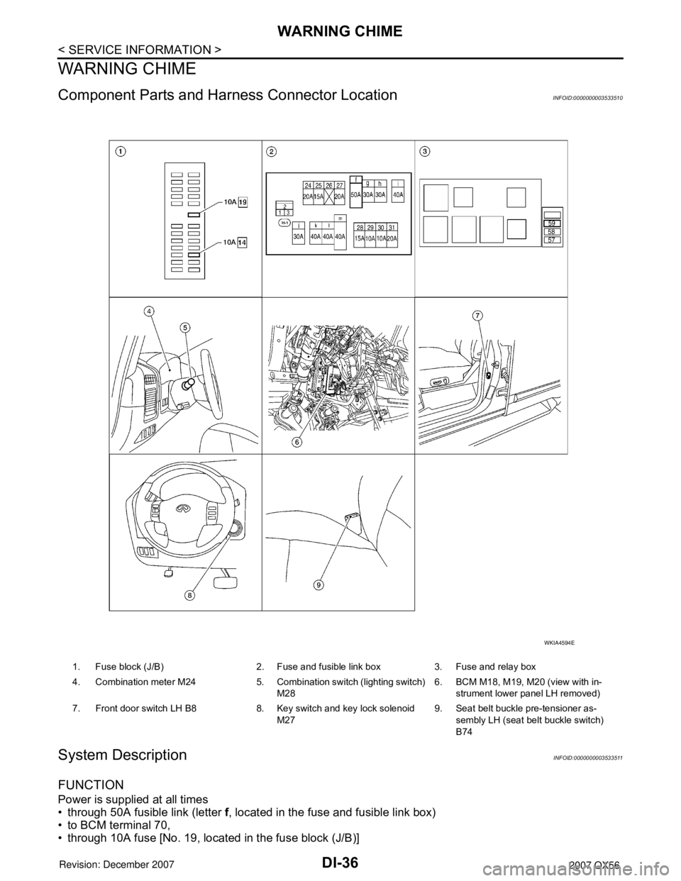
Component Parts and Harness Connector LocationINFOID:0000000003533510
System DescriptionINFOID:0000000003533511
FUNCTION
Power is supplied at all times
• through 50A fusible link (letter f, located in the fuse and fusible link box)
• to BCM terminal 70,
• through 10A fuse [No. 19, located in the fuse block (J/B)]
1. Fuse block (J/B) 2. Fuse and fusible link box 3. Fuse and relay box
4. Combination meter M24 5. Combination switch (lighting switch)
M286. BCM M18, M19, M20 (view with in-
strument lower panel LH removed)
7. Front door switch LH B8 8. Key switch and key lock solenoid
M279. Seat belt buckle pre-tensioner as-
sembly LH (seat belt buckle switch)
B74
WKIA4594E
Page 1048 of 3061
WARNING CHIME
DI-37
< SERVICE INFORMATION >
C
D
E
F
G
H
I
J
L
MA
B
DI
N
O
P
• to key switch and key lock solenoid terminal 3.
With ignition switch in ON or START position, power is supplied
• through 10A fuse (No. 59, located in the fuse and relay box)
• to BCM terminal 38.
Ground is supplied
• to BCM terminal 67
• through body grounds M57, M61, and M79.
NOTE:
When ignition key warning chime, light warning chime, and seat belt warning chime are required at the same
time, the priorities for each chime are the following.
1. Light warning chime
2. Ignition key warning chime
3. Seat belt warning chime
IGNITION KEY WARNING CHIME
With the key inserted in the ignition switch, the ignition switch in OFF position, and the driver's door open, the
warning chime will sound.
Power is supplied
• through key switch and key lock solenoid terminal 4
• to BCM terminal 37.
Ground is supplied
• to BCM terminal 47
• through front door switch LH terminal 2.
Front door switch LH is case grounded.
BCM detects key inserted into the ignition switch, and sends key warning signal to combination meter via CAN
communication lines. When the combination meter receives key warning signal, it sounds warning chime.
LIGHT WARNING CHIME
With the key removed from the ignition switch, the driver's door open, and the lighting switch (part of the com-
bination switch) in 1st or 2nd position, the warning chime will sound. [Except when headlamp battery saver
control operates (5 minutes after ignition switch is turned to OFF or ACC position) and headlamps do not illu-
minate.]
Signal is supplied
• from combination switch (lighting switch) terminals 1, 2, 3, 4, 5, 6, 7, 8, 9 and 10
• to BCM terminals 2, 3, 4, 5, 6, 32, 33, 34, 35 and 36.
NOTE:
BCM detected lighting switch in 1st or 2nd position. Refer to LT-72, "
Combination Switch Reading Function".
Ground is supplied
• to BCM terminal 47
• through front door switch LH terminal 2.
Front door switch LH is case grounded.
BCM detects headlamps are illuminated, and sends light warning signal to combination meter CAN communi-
cation lines. When the combination meter receives light warning signal, it sounds warning chime.
SEAT BELT WARNING CHIME
When the ignition switch is turned ON with the seat belt unfastened [seat belt buckle pre-tensioner assembly
LH (seat belt buckle switch) unfastened], warning chime will sound for approximately 6 seconds.
Ground is supplied
• to combination meter terminal 27
• through seat belt buckle pre-tensioner assembly LH (seat belt buckle switch) terminal 4.
Seat belt buckle pre-tensioner assembly LH (seat belt buckle switch) terminal 3 is grounded through body
grounds B7 and B19.
The combination meter sends seat belt buckle switch LH unfastened signal to BCM via CAN communication
line.
BCM receives seat belt buckle pre-tensioner assembly LH (seat belt buckle switch) unfastened signal from
combination meter via CAN communication line, and sends seat belt warning signal to the combination meter
via CAN communication line. When the combination meter receives the seat belt warning signal, it sounds the
warning chime. The BCM controls the (6 second) duration of the seat belt warning chime.
CAN Communication System DescriptionINFOID:0000000003533512
Refer to LAN-4.
Page 1053 of 3061
DI-42
< SERVICE INFORMATION >
WARNING CHIME
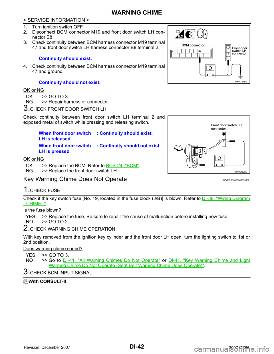
1. Turn ignition switch OFF.
2. Disconnect BCM connector M19 and front door switch LH con-
nector B8.
3. Check continuity between BCM harness connector M19 terminal
47 and front door switch LH harness connector B8 terminal 2.
4. Check continuity between BCM harness connector M19 terminal
47 and ground.
OK or NG
OK >> GO TO 3.
NG >> Repair harness or connector.
3.CHECK FRONT DOOR SWITCH LH
Check continuity between front door switch LH terminal 2 and
exposed metal of switch while pressing and releasing switch.
OK or NG
OK >> Replace the BCM. Refer to BCS-24, "BCM".
NG >> Replace the front door switch LH.
Key Warning Chime Does Not OperateINFOID:0000000003533521
1.CHECK FUSE
Check if the key switch fuse [No. 19, located in the fuse block (J/B)] is blown. Refer to DI-38, "
Wiring Diagram
- CHIME -".
Is the fuse blown?
YES >> Replace the fuse. Be sure to repair the cause of malfunction before installing new fuse.
NO >> GO TO 2.
2.CHECK WARNING CHIME OPERATION
With key removed from the ignition key cylinder and the front door LH open, turn the lighting switch to 1st or
2nd position.
Does warning chime sound?
YES >> GO TO 3.
NO >> Go to DI-41, "
All Warning Chimes Do Not Operate" or DI-41, "Key Warning Chime and Light
Warning Chime Do Not Operate (Seat Belt Warning Chime Does Operate)".
3.CHECK BCM INPUT SIGNAL
With CONSULT-IIContinuity should exist.
Continuity should not exist.
WKIA1516E
When front door switch
LH is released: Continuity should exist.
When front door switch
LH is pressed: Continuity should not exist.
WKIA2023E
Page 1055 of 3061
DI-44
< SERVICE INFORMATION >
WARNING CHIME
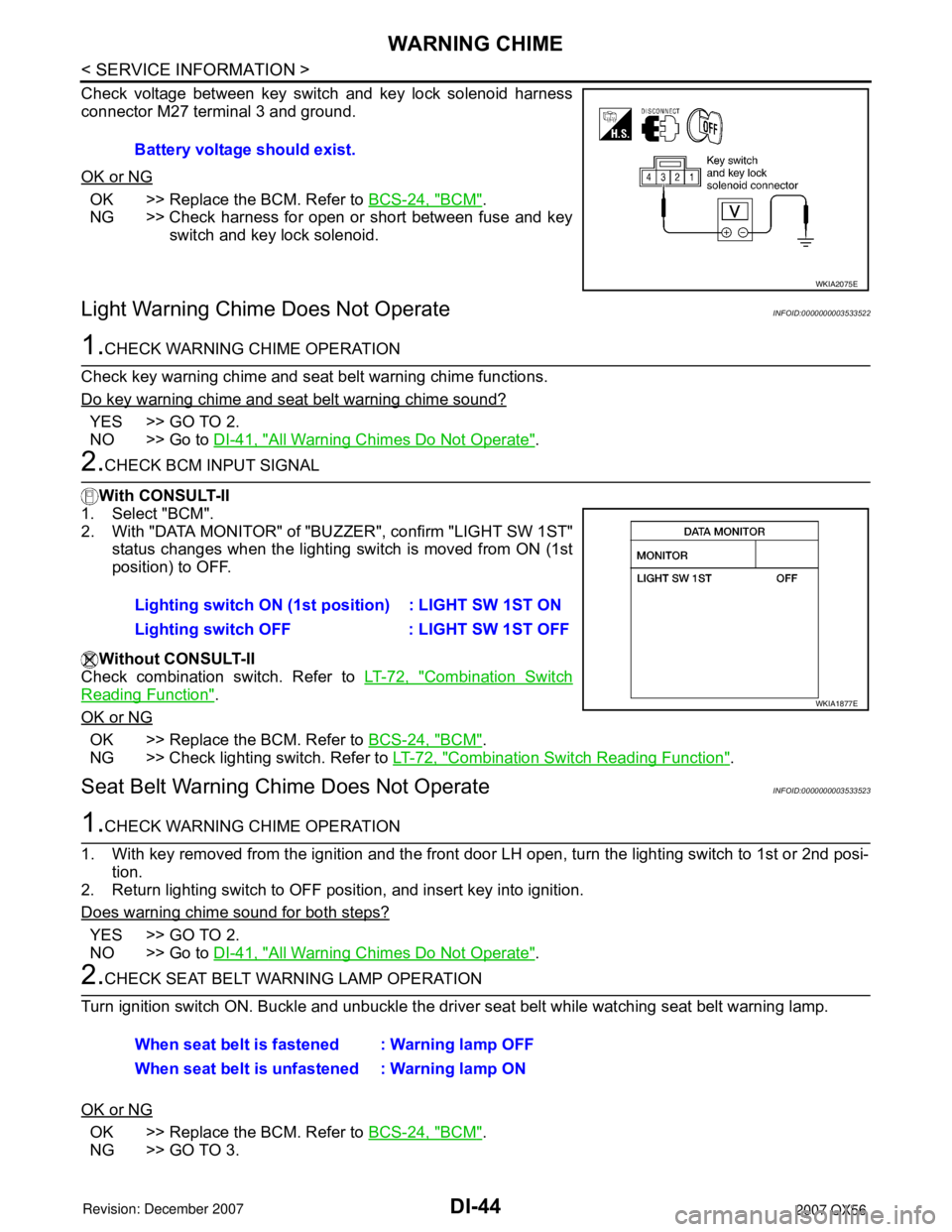
Check voltage between key switch and key lock solenoid harness
connector M27 terminal 3 and ground.
OK or NG
OK >> Replace the BCM. Refer to BCS-24, "BCM".
NG >> Check harness for open or short between fuse and key
switch and key lock solenoid.
Light Warning Chime Does Not OperateINFOID:0000000003533522
1.CHECK WARNING CHIME OPERATION
Check key warning chime and seat belt warning chime functions.
Do key warning chime and seat belt warning chime sound?
YES >> GO TO 2.
NO >> Go to DI-41, "
All Warning Chimes Do Not Operate".
2.CHECK BCM INPUT SIGNAL
With CONSULT-II
1. Select "BCM".
2. With "DATA MONITOR" of "BUZZER", confirm "LIGHT SW 1ST"
status changes when the lighting switch is moved from ON (1st
position) to OFF.
Without CONSULT-II
Check combination switch. Refer to LT-72, "
Combination Switch
Reading Function".
OK or NG
OK >> Replace the BCM. Refer to BCS-24, "BCM".
NG >> Check lighting switch. Refer to LT-72, "
Combination Switch Reading Function".
Seat Belt Warning Chime Does Not OperateINFOID:0000000003533523
1.CHECK WARNING CHIME OPERATION
1. With key removed from the ignition and the front door LH open, turn the lighting switch to 1st or 2nd posi-
tion.
2. Return lighting switch to OFF position, and insert key into ignition.
Does warning chime sound for both steps?
YES >> GO TO 2.
NO >> Go to DI-41, "
All Warning Chimes Do Not Operate".
2.CHECK SEAT BELT WARNING LAMP OPERATION
Turn ignition switch ON. Buckle and unbuckle the driver seat belt while watching seat belt warning lamp.
OK or NG
OK >> Replace the BCM. Refer to BCS-24, "BCM".
NG >> GO TO 3.Battery voltage should exist.
WKIA2075E
Lighting switch ON (1st position) : LIGHT SW 1ST ON
Lighting switch OFF : LIGHT SW 1ST OFF
WKIA1877E
When seat belt is fastened : Warning lamp OFF
When seat belt is unfastened : Warning lamp ON
Page 1733 of 3061
EI-4
< SERVICE INFORMATION >
SQUEAK AND RATTLE TROUBLE DIAGNOSIS
SQUEAK AND RATTLE TROUBLE DIAGNOSIS
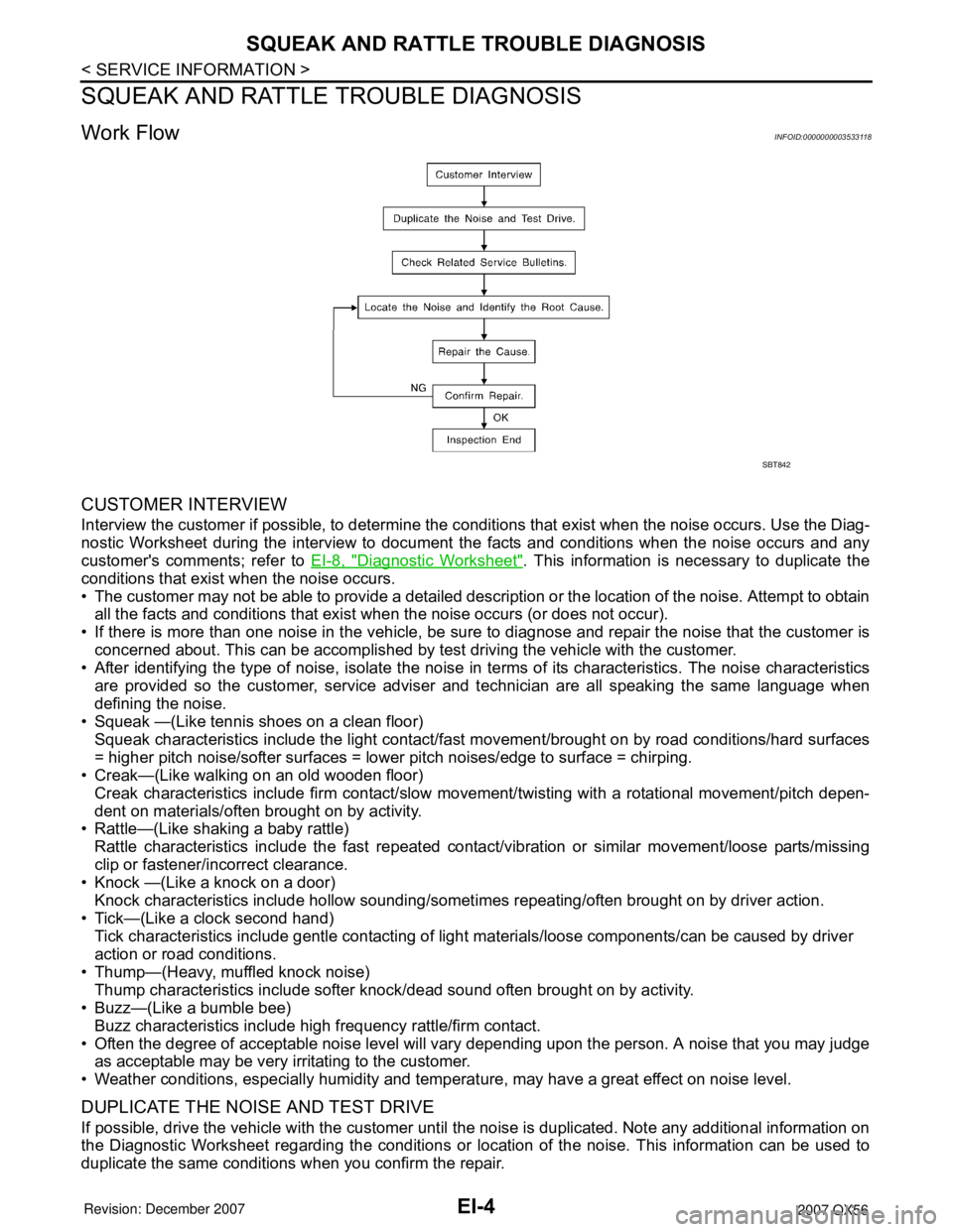
Work FlowINFOID:0000000003533118
CUSTOMER INTERVIEW
Interview the customer if possible, to determine the conditions that exist when the noise occurs. Use the Diag-
nostic Worksheet during the interview to document the facts and conditions when the noise occurs and any
customer's comments; refer to EI-8, "
Diagnostic Worksheet". This information is necessary to duplicate the
conditions that exist when the noise occurs.
• The customer may not be able to provide a detailed description or the location of the noise. Attempt to obtain
all the facts and conditions that exist when the noise occurs (or does not occur).
• If there is more than one noise in the vehicle, be sure to diagnose and repair the noise that the customer is
concerned about. This can be accomplished by test driving the vehicle with the customer.
• After identifying the type of noise, isolate the noise in terms of its characteristics. The noise characteristics
are provided so the customer, service adviser and technician are all speaking the same language when
defining the noise.
• Squeak —(Like tennis shoes on a clean floor)
Squeak characteristics include the light contact/fast movement/brought on by road conditions/hard surfaces
= higher pitch noise/softer surfaces = lower pitch noises/edge to surface = chirping.
• Creak—(Like walking on an old wooden floor)
Creak characteristics include firm contact/slow movement/twisting with a rotational movement/pitch depen-
dent on materials/often brought on by activity.
• Rattle—(Like shaking a baby rattle)
Rattle characteristics include the fast repeated contact/vibration or similar movement/loose parts/missing
clip or fastener/incorrect clearance.
• Knock —(Like a knock on a door)
Knock characteristics include hollow sounding/sometimes repeating/often brought on by driver action.
• Tick—(Like a clock second hand)
Tick characteristics include gentle contacting of light materials/loose components/can be caused by driver
action or road conditions.
• Thump—(Heavy, muffled knock noise)
Thump characteristics include softer knock/dead sound often brought on by activity.
• Buzz—(Like a bumble bee)
Buzz characteristics include high frequency rattle/firm contact.
• Often the degree of acceptable noise level will vary depending upon the person. A noise that you may judge
as acceptable may be very irritating to the customer.
• Weather conditions, especially humidity and temperature, may have a great effect on noise level.
DUPLICATE THE NOISE AND TEST DRIVE
If possible, drive the vehicle with the customer until the noise is duplicated. Note any additional information on
the Diagnostic Worksheet regarding the conditions or location of the noise. This information can be used to
duplicate the same conditions when you confirm the repair.
SBT842