2007 INFINITI QX56 belt
[x] Cancel search: beltPage 1826 of 3061
EM-56
< SERVICE INFORMATION >
CAMSHAFT
2. Perform the following procedure so as to prevent the engine from being unintentionally started while
checking.
a. Release fuel pressure. Refer to EC-80, "
Fuel Pressure Check".
b. Disconnect ignition coil and injector harness connectors if practical.
3. Remove IVT control solenoid valve.
4. Crank engine, and then make sure that engine oil comes out from IVT control cover oil hole. End cranking
after checking.
WARNING:
Be careful not to touch rotating parts (drive be lts, idler pulley, and crankshaft pulley, etc.).
CAUTION:
• Engine oil may squirt from IVT control soleno id valve installation hole during cranking. Use a
shop cloth to prevent engine oil from splashin g on worker, engine components and vehicle.
• Do not allow engine oil to get on rubber compon ents such as drive belts or engine mount insula-
tors. Immediately wipe off any splashed engine oil.
5. Clean oil groove between oil strainer and IVT control solenoid valve if engine oil does not come out from IVT control valve cover oil hole. Refer to LU-7, "
Schematic".
6. Remove components between IVT control solenoid va lve and camshaft sprocket (INT), and then check
each oil groove for clogging.
• Clean oil groove if necessary.
7. After inspection, installation of the remaining components is in the reverse order of removal.
Valve ClearanceINFOID:0000000003531536
INSPECTION
NOTE:
Perform the following inspection after removal, installation or replacement of camshaft or valve-related parts,
or if there are unusual engine conditions due to changes in valve clearance over time (starting, idling, and/or
noise).
1. Warm up the engine. Then stop the engine.
2. Remove the engine cover and. Refer to EM-12, "
Removal and Installation".
3. Remove the battery cover. Refer to SC-8, "
Removal and Installation".
4. Remove the air cleaner and air duct assembly EM-15, "
Removal and Installation".
5. Remove the RH bank and LH bank rocker covers using power tool. Refer to EM-35, "
Removal and Instal-
lation".
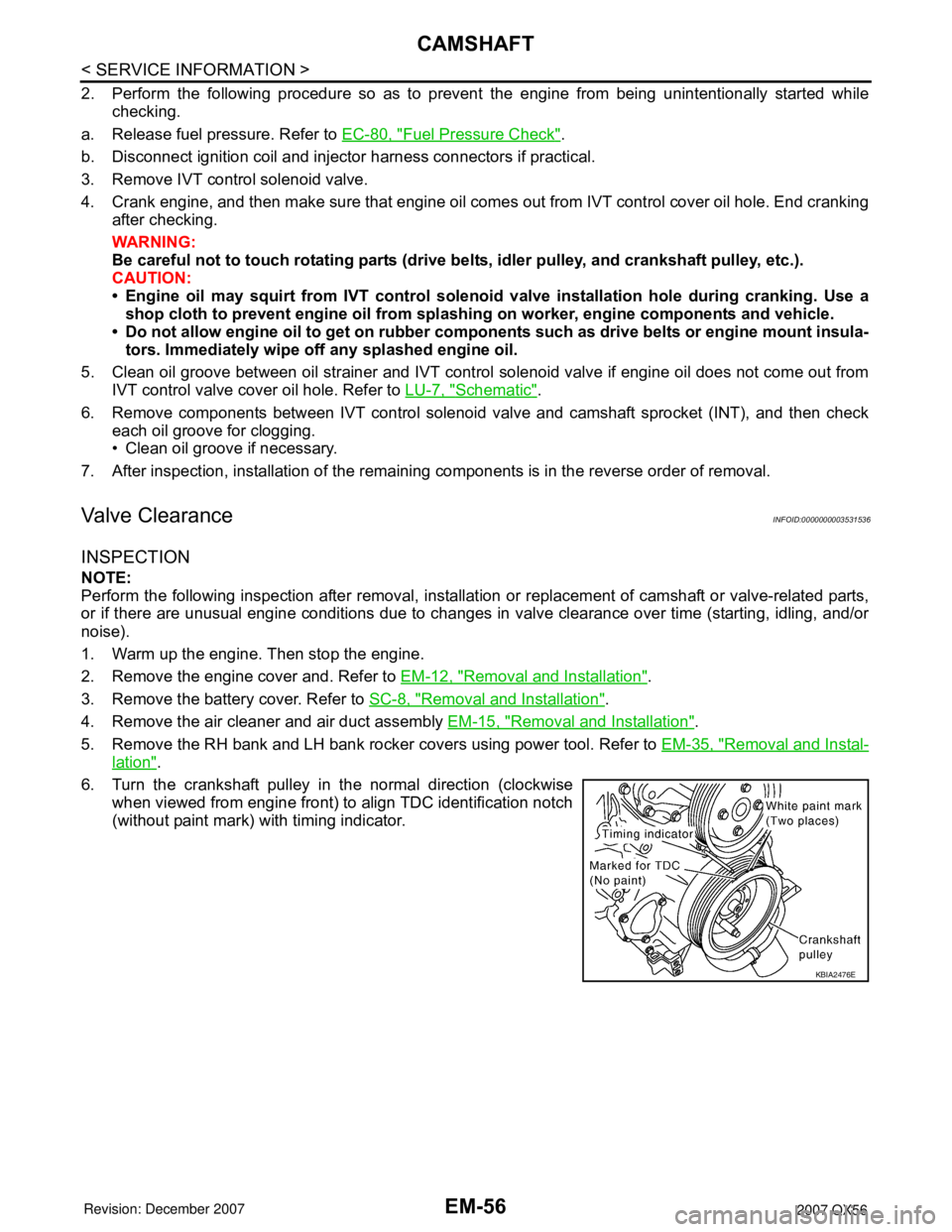
6. Turn the crankshaft pulley in the normal direction (clockwise when viewed from engine front) to align TDC identification notch
(without paint mark) with timing indicator.
KBIA2476E
Page 1835 of 3061
CYLINDER HEADEM-65
< SERVICE INFORMATION >
C
DE
F
G H
I
J
K L
M A
EM
NP
O
Removal and InstallationINFOID:0000000003531541
REMOVAL
1. Remove the engine assembly from the vehicle. Refer to
EM-74, "Removal and Installation".
2. Remove the following components and related parts: • Drive belt auto tensioner drive belts and idler pulley. Refer to EM-13, "
Removal and Installation".
• Thermostat housing and hose. Refer to CO-20, "
Removal and Installation".
• Oil pan and oil strainer. Refer to EM-24, "
Removal and Installation".
• Fuel tube and fuel injector assembly. Refer to EM-31, "
Removal and Installation".
• Intake manifold. Refer to EM-17, "
Removal and Installation".
• Ignition coil. Refer to EM-28, "
Removal and Installation".
• Rocker cover. Refer to EM-35, "
Removal and Installation".
3. Remove the crankshaft pulley, front cover, oil pump, and timing chain. Refer to EM-38, "
Removal and
Installation".
4. Remove the camshaft sprockets and camshafts. Refer to EM-46, "
Removal and Installation".
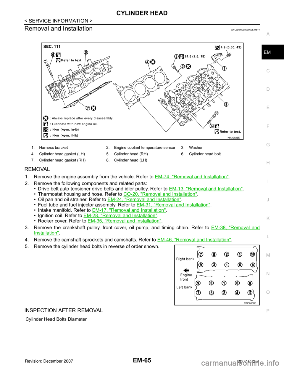
5. Remove the cylinder head bolts in reverse of order shown.
INSPECTION AFTER REMOVAL
Cylinder Head Bolts Diameter
1. Harness bracket 2. Engine coolant temperature sensor 3. Washer
4. Cylinder head gasket (LH) 5. Cylinder head (RH) 6. Cylinder head bolt
7. Cylinder head gasket (RH) 8. Cylinder head (LH)
KBIA2528E
PBIC0068E
Page 1845 of 3061
ENGINE ASSEMBLY
EM-75
< SERVICE INFORMATION >
C
D
E
F
G
H
I
J
K
L
MA
EM
N
P O
6. Remove the engine room cover using power tools.
7. Remove the air duct and air cleaner case assembly. Refer to EM-15, "
Removal and Installation".
8. Disconnect the vacuum hose between the vehicle and engine and set it aside.
9. Remove the radiator assembly and hoses. Refer to CO-13, "
Removal and Installation".
10. Remove the drive belts. Refer to EM-15, "
Removal and Installation".
11. Remove the fan blade. Refer to CO-16, "
Removal and Installation (Crankshaft Driven Type)".
12. Disconnect the engine room harness from the fuse box and set it aside.
13. Disconnect the ECM.
14. Disconnect the engine room harness from the engine side and set it aside.
15. Disconnect the engine harness grounds.
16. Disconnect the power steering reservoir tank from the engine and move it aside.
17. Disconnect the power steering oil pump from the engine. Move it aside and secure it using suitable wire or
rope. Refer to PS-21, "
Removal and Installation".
18. Remove the A/C compressor bolts and set the compressor aside. Refer to ATC-154, "
Removal and Instal-
lation for Compressor" (ATC).
19. Disconnect the brake booster vacuum line.
20. Disconnect the EVAP line.
21. Disconnect the fuel hose at the engine side connection. Refer to EM-31, "
Removal and Installation".
22. Disconnect the heater hoses at the cowl, and install plugs to avoid leakage of engine coolant.
23. Remove the A/T oil level indicator and indicator tube upper bolts.
24. Remove the front final drive assembly (4WD only). Refer to FFD-12, "
Removal and Installation".
25. Remove the exhaust manifolds. Refer to EM-21, "
Removal and Installation".
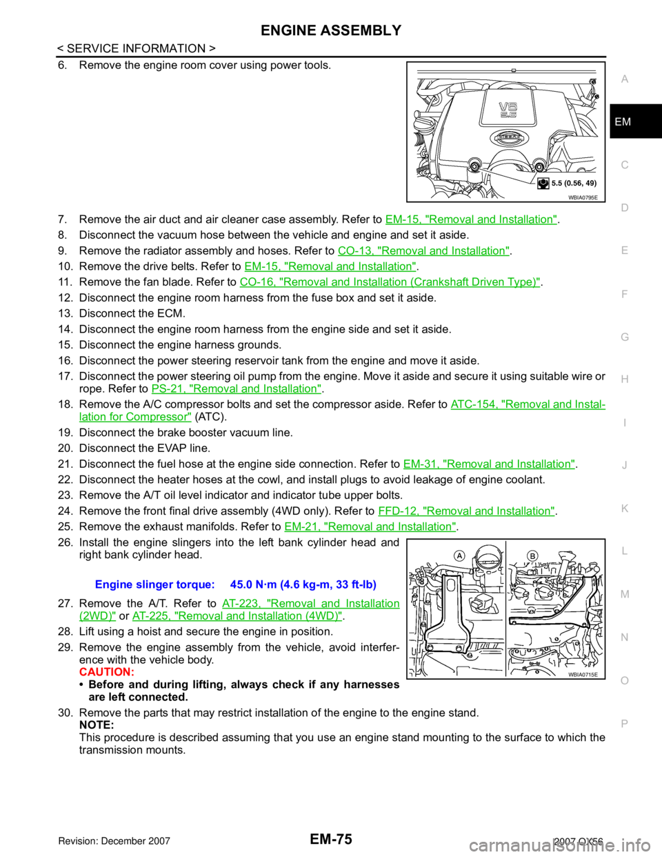
26. Install the engine slingers into the left bank cylinder head and
right bank cylinder head.
27. Remove the A/T. Refer to AT-223, "
Removal and Installation
(2WD)" or AT-225, "Removal and Installation (4WD)".
28. Lift using a hoist and secure the engine in position.
29. Remove the engine assembly from the vehicle, avoid interfer-
ence with the vehicle body.
CAUTION:
• Before and during lifting, always check if any harnesses
are left connected.
30. Remove the parts that may restrict installation of the engine to the engine stand.
NOTE:
This procedure is described assuming that you use an engine stand mounting to the surface to which the
transmission mounts.
WBIA0795E
Engine slinger torque: 45.0 N·m (4.6 kg-m, 33 ft-lb)
WBIA0715E
Page 1873 of 3061
SERVICE DATA AND SPECIFICATIONS (SDS)
EM-103
< SERVICE INFORMATION >
C
D
E
F
G
H
I
J
K
L
MA
EM
N
P O
SERVICE DATA AND SPECIFICATIONS (SDS)
Standard and LimitINFOID:0000000003531548
GENERAL SPECIFICATIONS
DRIVE BELTS
EXHAUST MANIFOLD
Cylinder arrangementV- 8
Displacement cm
3 (cu in)5,552 (338.80)
Bore and stroke mm (in)98 x 92 (3.86 x 3.62)
Valve arrangementDOHC
Firing order1-8-7-3-6-5-4-2
Number of piston ringsCompression 2
Oil 1
Number of main bearings5
Compression ratio9.8:1
C o m p r e s s i o n p r e s s u r e k P a
(kg/cm
2, psi)/rpmStandard 1,520 (15.5, 220)/200
Minimum 1,324 (13.5, 192)/200
Differential limit between cylinders 98 (1.0, 14)/200
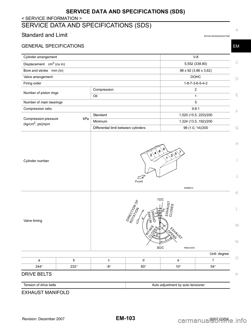
Cylinder number
Va l v e t i m i n g
Unit: degree
abcde f
244°232°-8°60°10°54°
SEM957C
PBIC0187E
Tension of drive belts Auto adjustment by auto tensioner
Page 1932 of 3061
FL-1
ENGINE
C
D
E
F
G
H
I
J
K
L
M
SECTION FL
A
FL
N
O
P
CONTENTS
FUEL SYSTEM
SERVICE INFORMATION ............................2
PRECAUTIONS ...................................................2
Precaution for Supplemental Restraint System
(SRS) "AIR BAG" and "SEAT BELT PRE-TEN-
SIONER" ...................................................................
2
PREPARATION ...................................................3
Special Service Tool .................................................3
Commercial Service Tool ..........................................3
FUEL SYSTEM ....................................................4
Checking Fuel Line ...................................................4
General Precaution ...................................................4
FUEL LEVEL SENSOR UNIT, FUEL FILTER
AND FUEL PUMP ASSEMBLY .........................
5
Removal and Installation ..........................................5
Disassembly and Assembly ......................................9
FUEL TANK ......................................................10
Removal and Installation .........................................10
SERVICE DATA AND SPECIFICATIONS
(SDS) .................................................................
15
Standard and Limit ..................................................15
Page 1933 of 3061
FL-2
< SERVICE INFORMATION >
PRECAUTIONS
SERVICE INFORMATION
PRECAUTIONS
Precaution for Supplemental Restraint System (SRS) "AIR BAG" and "SEAT BELT
PRE-TENSIONER"
INFOID:0000000003532200
The Supplemental Restraint System such as “AIR BAG” and “SEAT BELT PRE-TENSIONER”, used along
with a front seat belt, helps to reduce the risk or severity of injury to the driver and front passenger for certain
types of collision. This system includes seat belt switch inputs and dual stage front air bag modules. The SRS
system uses the seat belt switches to determine the front air bag deployment, and may only deploy one front
air bag, depending on the severity of a collision and whether the front occupants are belted or unbelted.
Information necessary to service the system safely is included in the SRS and SB section of this Service Man-
ual.
WARNING:
• To avoid rendering the SRS inoperative, which could increase the risk of personal injury or death in
the event of a collision which would result in air bag inflation, all maintenance must be performed by
an authorized NISSAN/INFINITI dealer.
• Improper maintenance, including incorrect removal and installation of the SRS, can lead to personal
injury caused by unintentional activation of the system. For removal of Spiral Cable and Air Bag
Module, see the SRS section.
• Do not use electrical test equipment on any circuit related to the SRS unless instructed to in this
Service Manual. SRS wiring harnesses can be identified by yellow and/or orange harnesses or har-
ness connectors.
Page 1937 of 3061
FL-6
< SERVICE INFORMATION >
FUEL LEVEL SENSOR UNIT, FUEL FILTER AND FUEL PUMP ASSEMBLY
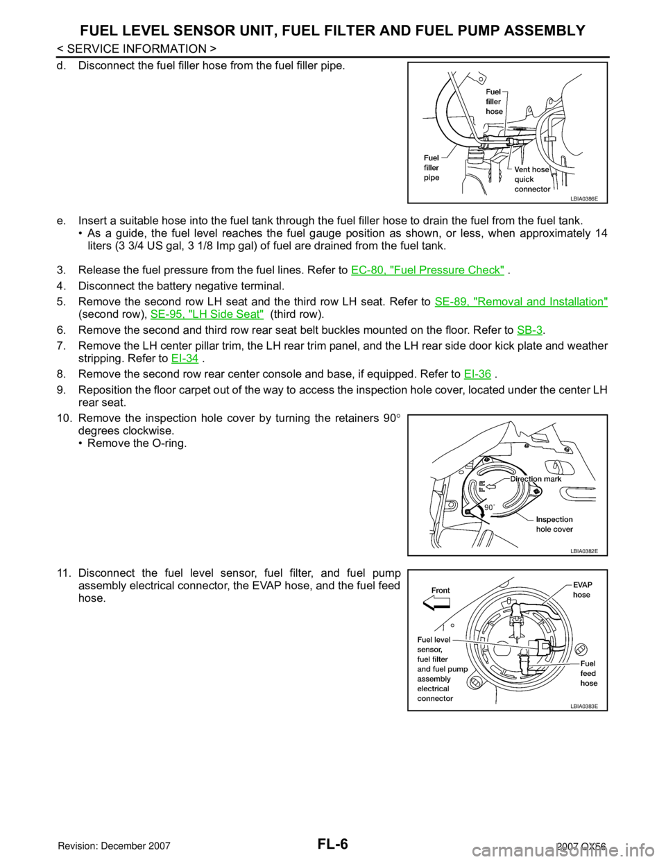
d. Disconnect the fuel filler hose from the fuel filler pipe.
e. Insert a suitable hose into the fuel tank through the fuel filler hose to drain the fuel from the fuel tank.
• As a guide, the fuel level reaches the fuel gauge position as shown, or less, when approximately 14
liters (3 3/4 US gal, 3 1/8 Imp gal) of fuel are drained from the fuel tank.
3. Release the fuel pressure from the fuel lines. Refer to EC-80, "
Fuel Pressure Check" .
4. Disconnect the battery negative terminal.
5. Remove the second row LH seat and the third row LH seat. Refer to SE-89, "
Removal and Installation"
(second row), SE-95, "LH Side Seat" (third row).
6. Remove the second and third row rear seat belt buckles mounted on the floor. Refer to SB-3
.
7. Remove the LH center pillar trim, the LH rear trim panel, and the LH rear side door kick plate and weather
stripping. Refer to EI-34
.
8. Remove the second row rear center console and base, if equipped. Refer to EI-36
.
9. Reposition the floor carpet out of the way to access the inspection hole cover, located under the center LH
rear seat.
10. Remove the inspection hole cover by turning the retainers 90°
degrees clockwise.
• Remove the O-ring.
11. Disconnect the fuel level sensor, fuel filter, and fuel pump
assembly electrical connector, the EVAP hose, and the fuel feed
hose.
LBIA0386E
LBIA0382E
LBIA0383E
Page 1942 of 3061
FUEL TANK
FL-11
< SERVICE INFORMATION >
C
D
E
F
G
H
I
J
K
L
MA
FL
N
P O
REMOVAL
WARNING:
Follow the “General Precautions” before working on the fuel system. Refer to GI-3, "
General Precau-
tion" .
1. Drain the fuel from the fuel tank, if necessary.
• Position the vehicle so it is level.
2. Remove the fuel filler cap to release the pressure from inside the fuel tank.
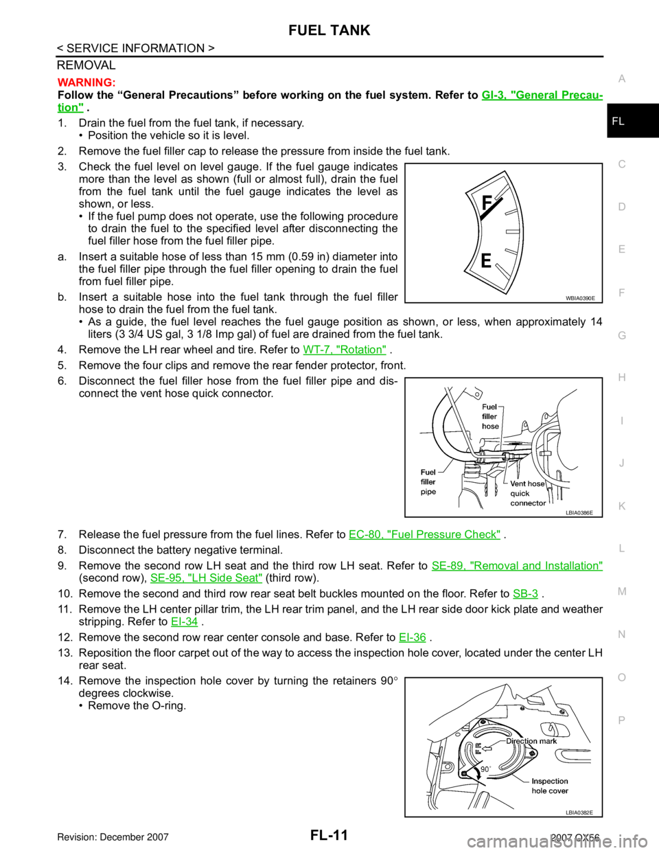
3. Check the fuel level on level gauge. If the fuel gauge indicates
more than the level as shown (full or almost full), drain the fuel
from the fuel tank until the fuel gauge indicates the level as
shown, or less.
• If the fuel pump does not operate, use the following procedure
to drain the fuel to the specified level after disconnecting the
fuel filler hose from the fuel filler pipe.
a. Insert a suitable hose of less than 15 mm (0.59 in) diameter into
the fuel filler pipe through the fuel filler opening to drain the fuel
from fuel filler pipe.
b. Insert a suitable hose into the fuel tank through the fuel filler
hose to drain the fuel from the fuel tank.
• As a guide, the fuel level reaches the fuel gauge position as shown, or less, when approximately 14
liters (3 3/4 US gal, 3 1/8 Imp gal) of fuel are drained from the fuel tank.
4. Remove the LH rear wheel and tire. Refer to WT-7, "
Rotation" .
5. Remove the four clips and remove the rear fender protector, front.
6. Disconnect the fuel filler hose from the fuel filler pipe and dis-
connect the vent hose quick connector.
7. Release the fuel pressure from the fuel lines. Refer to EC-80, "
Fuel Pressure Check" .
8. Disconnect the battery negative terminal.
9. Remove the second row LH seat and the third row LH seat. Refer to SE-89, "
Removal and Installation"
(second row), SE-95, "LH Side Seat" (third row).
10. Remove the second and third row rear seat belt buckles mounted on the floor. Refer to SB-3
.
11. Remove the LH center pillar trim, the LH rear trim panel, and the LH rear side door kick plate and weather
stripping. Refer to EI-34
.
12. Remove the second row rear center console and base. Refer to EI-36
.
13. Reposition the floor carpet out of the way to access the inspection hole cover, located under the center LH
rear seat.
14. Remove the inspection hole cover by turning the retainers 90°
degrees clockwise.
• Remove the O-ring.
WBIA0390E
LBIA0386E
LBIA0382E