2007 INFINITI QX56 belt
[x] Cancel search: beltPage 2114 of 3061

IP-2
< SERVICE INFORMATION >
PRECAUTIONS
SERVICE INFORMATION
PRECAUTIONS
Precaution for Supplemental Restraint System (SRS) "AIR BAG" and "SEAT BELT
PRE-TENSIONER"
INFOID:0000000003533141
The Supplemental Restraint System such as “AIR BAG” and “SEAT BELT PRE-TENSIONER”, used along
with a front seat belt, helps to reduce the risk or severity of injury to the driver and front passenger for certain
types of collision. This system includes seat belt switch inputs and dual stage front air bag modules. The SRS
system uses the seat belt switches to determine the front air bag deployment, and may only deploy one front
air bag, depending on the severity of a collision and whether the front occupants are belted or unbelted.
Information necessary to service the system safely is included in the SRS and SB section of this Service Man-
ual.
WARNING:
• To avoid rendering the SRS inoperative, which could increase the risk of personal injury or death in
the event of a collision which would result in air bag inflation, all maintenance must be performed by
an authorized NISSAN/INFINITI dealer.
• Improper maintenance, including incorrect removal and installation of the SRS, can lead to personal
injury caused by unintentional activation of the system. For removal of Spiral Cable and Air Bag
Module, see the SRS section.
• Do not use electrical test equipment on any circuit related to the SRS unless instructed to in this
Service Manual. SRS wiring harnesses can be identified by yellow and/or orange harnesses or har-
ness connectors.
Page 2132 of 3061

LAN-1
ELECTRICAL
C
D
E
F
G
H
I
J
L
M
SECTION LAN
A
B
LAN
N
O
P
CONTENTS
LAN SYSTEM
CAN FUNDAMENTAL
SERVICE INFORMATION ............................
3
PRECAUTIONS ...................................................3
Precaution When Using CONSULT-II .......................3
Precaution for Trouble Diagnosis ..............................3
Precaution for Harness Repair ..................................3
SYSTEM DESCRIPTION .....................................4
CAN Communication System ....................................4
Diag on CAN .............................................................5
TROUBLE DIAGNOSIS ......................................7
Condition of Error Detection ......................................7
Symptom When Error Occurs in CAN Communi-
cation System ............................................................
7
Self-Diagnosis .........................................................10
CAN Diagnostic Support Monitor ............................10
TROUBLE DIAGNOSES WORK FLOW ............13
Information Needed for Trouble Diagnosis .............13
How to Use CAN Communication Signal Chart ......13
Trouble Diagnosis Flow Chart .................................14
Trouble Diagnosis Procedure ..................................14
CAN
SERVICE INFORMATION ...........................
36
INDEX FOR DTC ................................................36
DTC No. Index ........................................................36
HOW TO USE THIS SECTION ...........................37
Caution ....................................................................37
Abbreviation List ......................................................37
PRECAUTIONS ..................................................38
Precaution for Supplemental Restraint System
(SRS) "AIR BAG" and "SEAT BELT PRE-TEN-
SIONER" .................................................................
38
Precaution When Using CONSULT-II .....................38
Precaution for Trouble Diagnosis ............................38
Precaution for Harness Repair ................................38
TROUBLE DIAGNOSIS ....................................40
CAN Diagnostic Support Monitor .............................40
CAN System Specification Chart .............................44
CAN Communication Signal Chart ..........................44
Schematic ................................................................49
Wiring Diagram - CAN - ...........................................50
Interview Sheet ........................................................53
Data Sheet ...............................................................54
CAN System (Type 1) ..............................................57
CAN System (Type 2) ..............................................58
CAN System (Type 3) ..............................................59
CAN System (Type 4) ..............................................60
Component Parts Location ......................................61
Harness Layout .......................................................61
Malfunction Area Chart ............................................61
Main Line Between TCM and Driver Seat Control
Unit ..........................................................................
62
Main Line Between TCM and ICC Sensor ...............63
Main Line Between ICC Sensor and ICC Unit .........64
Main Line Between ICC Unit and Driver Seat Con-
trol Unit ....................................................................
65
Main Line Between Driver Seat Control Unit and
Data Link Connector ................................................
65
Main Line Between Data Link Connector and ABS
Actuator and Electric Unit (Control Unit) ..................
66
ECM Branch Line Circuit .........................................67
TCM Branch Line Circuit .........................................67
ICC Sensor Branch Line Circuit ...............................68
ICC Unit Branch Line Circuit ....................................69
Driver Seat Control Unit Branch Line Circuit ...........69
BCM Branch Line Circuit .........................................70
Display Control Unit Branch Line Circuit .................70
Data Link Connector Branch Line Circuit ................71
Front Air Control Branch Line Circuit .......................71
Combination Meter Branch Line Circuit ...................72
Steering Angle Sensor Branch Line Circuit .............72
Transfer Control Unit Branch Line Circuit ................73
ABS Actuator and Electric Unit (Control Unit)
Branch Line Circuit ..................................................
74
Page 2169 of 3061
![INFINITI QX56 2007 Factory Service Manual LAN-38
< SERVICE INFORMATION >[CAN]
PRECAUTIONS
PRECAUTIONS
Precaution for Supplemental Restraint System (SRS) "AIR BAG" and "SEAT BELT
PRE-TENSIONER"
INFOID:0000000003533622
The Supplemental Restrai INFINITI QX56 2007 Factory Service Manual LAN-38
< SERVICE INFORMATION >[CAN]
PRECAUTIONS
PRECAUTIONS
Precaution for Supplemental Restraint System (SRS) "AIR BAG" and "SEAT BELT
PRE-TENSIONER"
INFOID:0000000003533622
The Supplemental Restrai](/manual-img/42/57029/w960_57029-2168.png)
LAN-38
< SERVICE INFORMATION >[CAN]
PRECAUTIONS
PRECAUTIONS
Precaution for Supplemental Restraint System (SRS) "AIR BAG" and "SEAT BELT
PRE-TENSIONER"
INFOID:0000000003533622
The Supplemental Restraint System such as “AIR BAG” and “SEAT BELT PRE-TENSIONER”, used along
with a front seat belt, helps to reduce the risk or severity of injury to the driver and front passenger for certain
types of collision. This system includes seat belt switch inputs and dual stage front air bag modules. The SRS
system uses the seat belt switches to determine the front air bag deployment, and may only deploy one front
air bag, depending on the severity of a collision and whether the front occupants are belted or unbelted.
Information necessary to service the system safely is included in the SRS and SB section of this Service Man-
ual.
WARNING:
• To avoid rendering the SRS inoperative, which could increase the risk of personal injury or death in
the event of a collision which would result in air bag inflation, all maintenance must be performed by
an authorized NISSAN/INFINITI dealer.
• Improper maintenance, including incorrect removal and installation of the SRS, can lead to personal
injury caused by unintentional activation of the system. For removal of Spiral Cable and Air Bag
Module, see the SRS section.
• Do not use electrical test equipment on any circuit related to the SRS unless instructed to in this
Service Manual. SRS wiring harnesses can be identified by yellow and/or orange harnesses or har-
ness connectors.
Precaution When Using CONSULT-IIINFOID:0000000003533623
Use CONSULT-II CONVERTER when connecting CONSULT-II to data link connector.
CAUTION:
CAN communication does not function properly if CONSULT-II is used without connecting CONSULT-II
CONVERTER.
Precaution for Trouble DiagnosisINFOID:0000000003533624
CAUTION:
• Never apply 7.0 V or more to the measurement terminal.
• Use a tester with open terminal voltage of 7.0 V or less.
• Turn the ignition switch OFF and disconnect the battery cable from the negative terminal when
checking the harness.
Precaution for Harness RepairINFOID:0000000003533625
• Solder the repaired area and wrap tape around the soldered area.
NOTE:
A fray of twisted lines must be within 110 mm (4.33 in).
SKIB8766E
Page 2208 of 3061

LT-1
ELECTRICAL
C
D
E
F
G
H
I
J
L
M
SECTION LT
A
B
LT
N
O
P
CONTENTS
LIGHTING SYSTEM
SERVICE INFORMATION ............................4
PRECAUTIONS ...................................................4
Precaution for Supplemental Restraint System
(SRS) "AIR BAG" and "SEAT BELT PRE-TEN-
SIONER" ...................................................................
4
General precautions for service operations ..............4
HEADLAMP (FOR USA) .....................................5
Component Parts and Harness Connector Loca-
tion ............................................................................
5
System Description ...................................................5
CAN Communication System Description .................7
Schematic .................................................................7
Wiring Diagram - H/LAMP - .......................................8
Terminal and Reference Value for BCM .................11
Terminal and Reference Value for IPDM E/R .........11
How to Proceed with Trouble Diagnosis .................12
Preliminary Check ...................................................12
CONSULT-II Function (BCM) ..................................12
CONSULT-II Function (IPDM E/R) ..........................13
Headlamp HI Does Not Illuminate (Both Sides) ......14
Headlamp HI Does Not Illuminate (One Side) ........15
High Beam Indicator Lamp Does Not Illuminate .....16
Headlamp LO Does Not Illuminate (Both Sides) .....17
Headlamp LO Does Not Illuminate (One Side) .......18
Headlamps Do Not Turn OFF .................................19
Aiming Adjustment ..................................................20
Bulb Replacement ...................................................21
Removal and Installation .........................................22
Disassembly and Assembly ....................................23
HEADLAMP (FOR CANADA) - DAYTIME
LIGHT SYSTEM - ...............................................
24
Component Parts and Harness Connector Loca-
tion ..........................................................................
24
System Description .................................................24
CAN Communication System Description ...............25
Schematic ...............................................................26
Wiring Diagram - DTRL - .........................................27
Terminal and Reference Value for BCM .................30
How to Proceed with Trouble Diagnosis ..................30
Preliminary Check ...................................................31
CONSULT-II Function for BCM ...............................32
CONSULT-II Function for IPDM E/R .......................32
Daytime Light Control Does Not Operate Properly
(Normal Headlamps Operate Properly) ...................
32
Aiming Adjustment ...................................................33
Bulb Replacement ...................................................33
Removal and Installation .........................................33
Disassembly and Assembly .....................................33
AUTO LIGHT SYSTEM .....................................34
Component Parts and Harness Connector Loca-
tion ...........................................................................
34
System Description ..................................................34
CAN Communication System Description ...............35
Major Component and Functions ............................35
Schematic ................................................................36
Wiring Diagram - AUTO/L - .....................................37
Terminal and Reference Value for BCM ..................39
Terminal and Reference Value for IPDM E/R ..........39
How to Proceed with Trouble Diagnosis ..................40
Preliminary Check ...................................................40
CONSULT-II Function (BCM) ..................................40
CONSULT-II Function (IPDM E/R) ..........................41
Trouble Diagnosis Chart by Symptom .....................42
Lighting Switch Inspection .......................................42
Optical Sensor System Inspection ...........................43
Optical Sensor .........................................................44
HEADLAMP AIMING CONTROL ......................45
System Description ..................................................45
Wiring Diagram - H/AIM - ........................................46
Headlamp Aiming Switch .........................................47
Switch Circuit Inspection .........................................48
FRONT FOG LAMP ..........................................49
Component Parts and Harness Connector Loca-
tion ...........................................................................
49
System Description ..................................................49
CAN Communication System Description ...............50
Page 2211 of 3061

LT-4
< SERVICE INFORMATION >
PRECAUTIONS
SERVICE INFORMATION
PRECAUTIONS
Precaution for Supplemental Restraint System (SRS) "AIR BAG" and "SEAT BELT
PRE-TENSIONER"
INFOID:0000000003533330
The Supplemental Restraint System such as “AIR BAG” and “SEAT BELT PRE-TENSIONER”, used along
with a front seat belt, helps to reduce the risk or severity of injury to the driver and front passenger for certain
types of collision. This system includes seat belt switch inputs and dual stage front air bag modules. The SRS
system uses the seat belt switches to determine the front air bag deployment, and may only deploy one front
air bag, depending on the severity of a collision and whether the front occupants are belted or unbelted.
Information necessary to service the system safely is included in the SRS and SB section of this Service Man-
ual.
WARNING:
• To avoid rendering the SRS inoperative, which could increase the risk of personal injury or death in
the event of a collision which would result in air bag inflation, all maintenance must be performed by
an authorized NISSAN/INFINITI dealer.
• Improper maintenance, including incorrect removal and installation of the SRS, can lead to personal
injury caused by unintentional activation of the system. For removal of Spiral Cable and Air Bag
Module, see the SRS section.
• Do not use electrical test equipment on any circuit related to the SRS unless instructed to in this
Service Manual. SRS wiring harnesses can be identified by yellow and/or orange harnesses or har-
ness connectors.
General precautions for service operationsINFOID:0000000003533331
• Never work with wet hands.
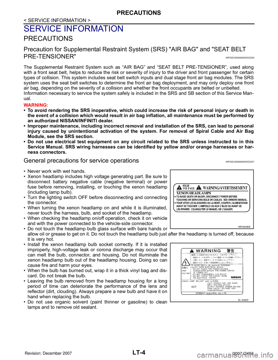
• Xenon headlamp includes high voltage generating part. Be sure to
disconnect battery negative cable (negative terminal) or power
fuse before removing, installing, or touching the xenon headlamp
(including lamp bulb).
• Turn the lighting switch OFF before disconnecting and connecting
the connector.
• When turning the xenon headlamp on and while it is illuminated,
never touch the harness, bulb, and socket of the headlamp.
• When checking the headlamp on/off operation, check it on vehicle
and with the power connected to the vehicle-side connector.
• Do not touch the headlamp bulb glass surface with bare hands or
allow oil or grease to get on it. Do not touch the headlamp bulb just after the headlamp is turned off, because
it is very hot.
• Install the xenon headlamp bulb socket correctly. If it is installed
improperly, high-voltage leak or corona discharge may occur that
can melt the bulb, connector, and housing. Do not illuminate the
xenon headlamp bulb out of the headlamp housing. Doing so can
cause fire and harm your eyes.
• When the bulb has burned out, wrap it in a thick vinyl bag and dis-
card. Do not break the bulb.
• Leaving the bulb removed from the headlamp housing for a long
period of time can deteriorate the performance of the lens and
reflector (dirt, clouding). Always prepare a new bulb and have it on
hand when replacing the bulb.
• Do not use organic solvent (paint thinner or gasoline) to clean
lamps and to remove old sealant.
WKIA0460E
EL-3422D
Page 2346 of 3061

LU-1
ENGINE
C
D
E
F
G
H
I
J
K
L
M
SECTION LU
A
LU
N
O
P
CONTENTS
ENGINE LUBRICATION SYSTEM
SERVICE INFORMATION ............................2
PRECAUTIONS ...................................................2
Precaution for Supplemental Restraint System
(SRS) "AIR BAG" and "SEAT BELT PRE-TEN-
SIONER" ...................................................................
2
Precaution for Liquid Gasket .....................................2
PREPARATION ...................................................4
Special Service Tool .................................................4
Commercial Service Tool ..........................................4
LUBRICATION SYSTEM ....................................6
Lubrication Circuit .....................................................6
Schematic .................................................................7
ENGINE OIL ........................................................8
Inspection .................................................................8
Changing Engine Oil .................................................9
OIL FILTER .......................................................11
Removal and Installation .........................................11
OIL COOLER ....................................................12
Removal and Installation .........................................12
OIL PUMP .........................................................14
Removal and Installation .........................................14
Disassembly and Assembly .....................................15
SERVICE DATA AND SPECIFICATIONS
(SDS) .................................................................
17
Standard and Limit ..................................................17
Page 2347 of 3061

LU-2
< SERVICE INFORMATION >
PRECAUTIONS
SERVICE INFORMATION
PRECAUTIONS
Precaution for Supplemental Restraint System (SRS) "AIR BAG" and "SEAT BELT
PRE-TENSIONER"
INFOID:0000000003531549
The Supplemental Restraint System such as “AIR BAG” and “SEAT BELT PRE-TENSIONER”, used along
with a front seat belt, helps to reduce the risk or severity of injury to the driver and front passenger for certain
types of collision. Information necessary to service the system safely is included in the SRS and SB section of
this Service Manual.
WARNING:
• To avoid rendering the SRS inoperative, which could increase the risk of personal injury or death in
the event of a collision which would result in air bag inflation, all maintenance must be performed by
an authorized NISSAN/INFINITI dealer.
• Improper maintenance, including incorrect removal and installation of the SRS, can lead to personal
injury caused by unintentional activation of the system. For removal of Spiral Cable and Air Bag
Module, see the SRS section.
• Do not use electrical test equipment on any circuit related to the SRS unless instructed to in this
Service Manual. SRS wiring harnesses can be identified by yellow and/or orange harnesses or har-
ness connectors.
Precaution for Liquid GasketINFOID:0000000003531550
REMOVAL OF LIQUID GASKET SEALING
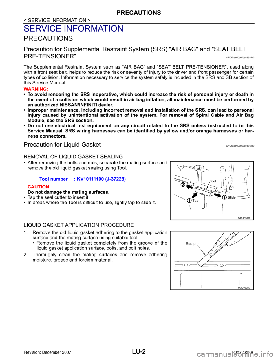
• After removing the bolts and nuts, separate the mating surface and
remove the old liquid gasket sealing using Tool.
CAUTION:
Do not damage the mating surfaces.
• Tap the seal cutter to insert it.
• In areas where the Tool is difficult to use, lightly tap to slide it.
LIQUID GASKET APPLICATION PROCEDURE
1. Remove the old liquid gasket adhering to the gasket application
surface and the mating surface using suitable tool.
• Remove the liquid gasket completely from the groove of the
liquid gasket application surface, bolts, and bolt holes.
2. Thoroughly clean the mating surfaces and remove adhering
moisture, grease and foreign material.Tool number : KV10111100 (J-37228)
WBIA0566E
PBIC0003E
Page 2356 of 3061

OIL FILTER
LU-11
< SERVICE INFORMATION >
C
D
E
F
G
H
I
J
K
L
MA
LU
N
P O
OIL FILTER
Removal and InstallationINFOID:0000000003531557
REMOVAL
1. Remove the engine front undercover using power tool.
2. Remove the oil filter using Tool.
WARNING:
• The oil filter is provided with a relief valve.
Use Genuine NISSAN oil filter or equivalent.
• When removing, prepare a shop cloth to absorb any
engine oil leakage or spillage.
• Do not allow engine oil to adhere to the drive belts.
• Completely wipe off any engine oil that adheres to the
engine and the vehicle.
CAUTION:
• Be careful not to get burned when the engine and engine oil are hot.
INSTALLATION
1. Remove foreign materials adhering to the oil filter installation surface.
2. Apply engine oil to the oil seal circumference of the new oil filter.
3. Screw the oil filter manually until it touches the installation sur-
face, then tighten it by 2/3 turn. Or tighten to specification.
4. Inspect the engine for oil leakage. Refer to EM-74, "
Removal
and Installation".
5. Install the engine front undercover using power tool.
INSPECTION AFTER INSTALLATION
1. Check the engine oil level. Refer to LU-8, "Inspection".
2. Start the engine and check for engine oil leakage.
3. Stop the engine and wait for 10 minutes.
4. Check the engine oil level and add engine oil as required.Tool number : KV10115801 (J-38956)
WBIA0388E
SMA010
Oil filter : 17.7 N·m (1.8 kg-m, 13 ft-lb)
SMA229B